Automatic dependent surveillance – broadcast (ADS–B out to be specific) are a series of periodic radio broadcasts made by aircrafts that are received by air traffic controls (ATCs) and other aircrafts allowing the broadcasting aircrafts to be tracked. Aircrafts receive navigation information (i.e. GPS location) from satellites and together with other information (i.e. aircraft type designators, course, and speed), rebroadcast them on the ADS-B out channel which is in turn received by ground-based receivers.
The received information are used to augment the less accurate aircraft positional information from primary and secondary radar. This ADS-B framework will form an essential part of the US Next Generation Air Transportation System (NextGen) and the Single European Sky ATM Research (SESAR) initiative, which promises more efficient and safer air travel by 2020.
Now the current problems faced -
The ADS-B network is currently unencrypted, making it vulnerable to attack. But that is another chapter I guess.
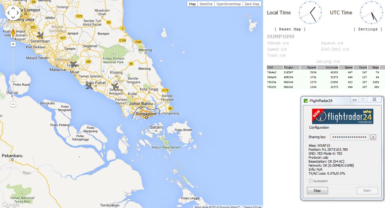
ADS-B is works on a microwave frequency of 1090 MHz which means that it is incapable of bouncing off the ionosphere making it essentially line-of-sight. Realistically, the broadcast will have a range of only about 300 miles or 483 km. On land this not so much of an issue as receivers can be readily deployed to increase coverage. In fact websites like flightradar24.com and flightaware.com are providing free ADS-B receivers for general public to host (subjected to location). Information received by these receivers are forwarded to their server which are then made available on the internet.
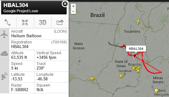
Tracking aircrafts over the oceans using ADS-B is a whole new ball game. There are no comprehensive ocean-borne receiver network for this purpose. Aireon, a subsidiary of Iridium Communications Inc estimates only about 10% of the earth surface (mostly on land) has coverage for ADS-B. They plan to launch and operate satellites with ADS-B receivers providing truly global coverage by 2017.
It would be an interesting exercise to see how almost off-the-shelf technology can address this problem from now to 2017. Here lies the premise of the Global Seer Project - To develop an autonomous ocean platform with an ADS-B receiver as its payload that can be deployed to a strategic location to act as a relay for ADS-B information. Information received by the platform can be relayed via satellite/shortwave radio or from platform to platform in a mesh network configuration to land.
Now here goes : At this early stage in the project there is a glaring lack of any details, but I will still endeavour to come up with a functional schematic for the Global Seer scheme -
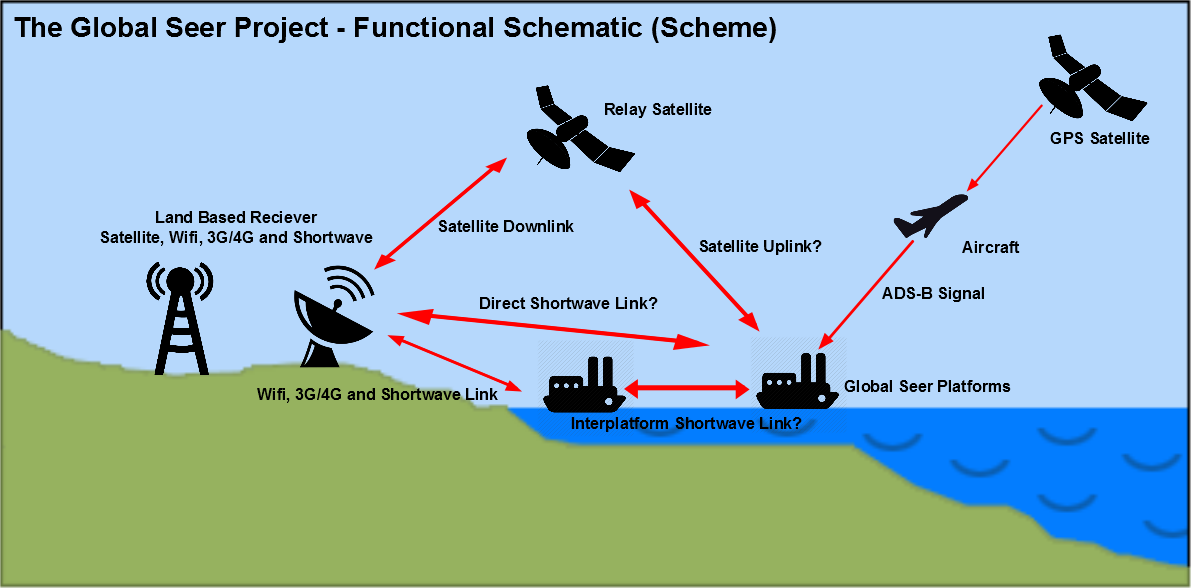
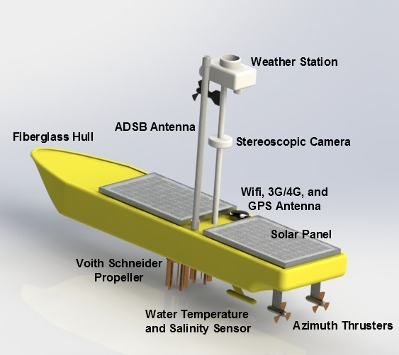
As far as I envisage the platform will need to have the following sections:
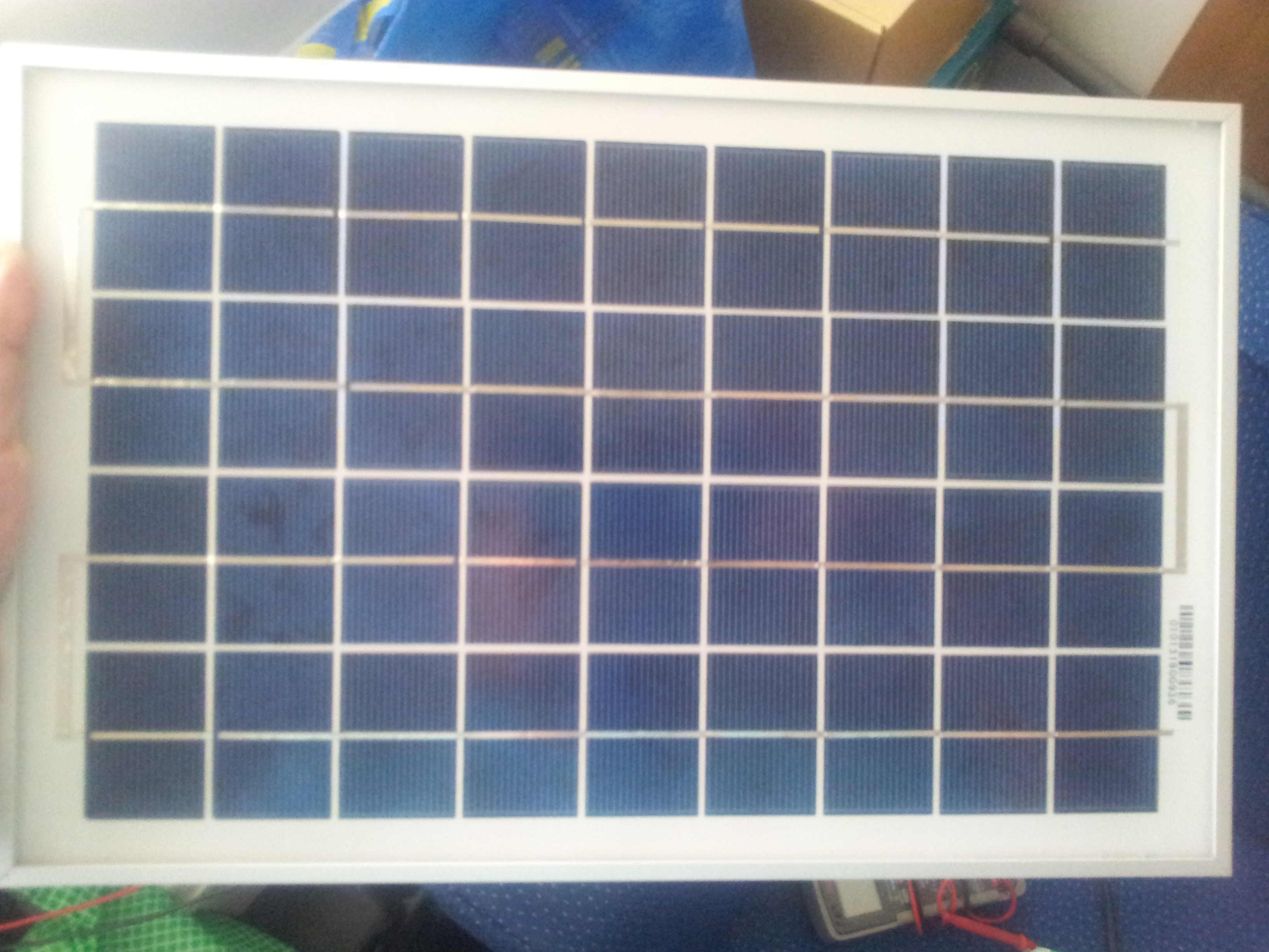
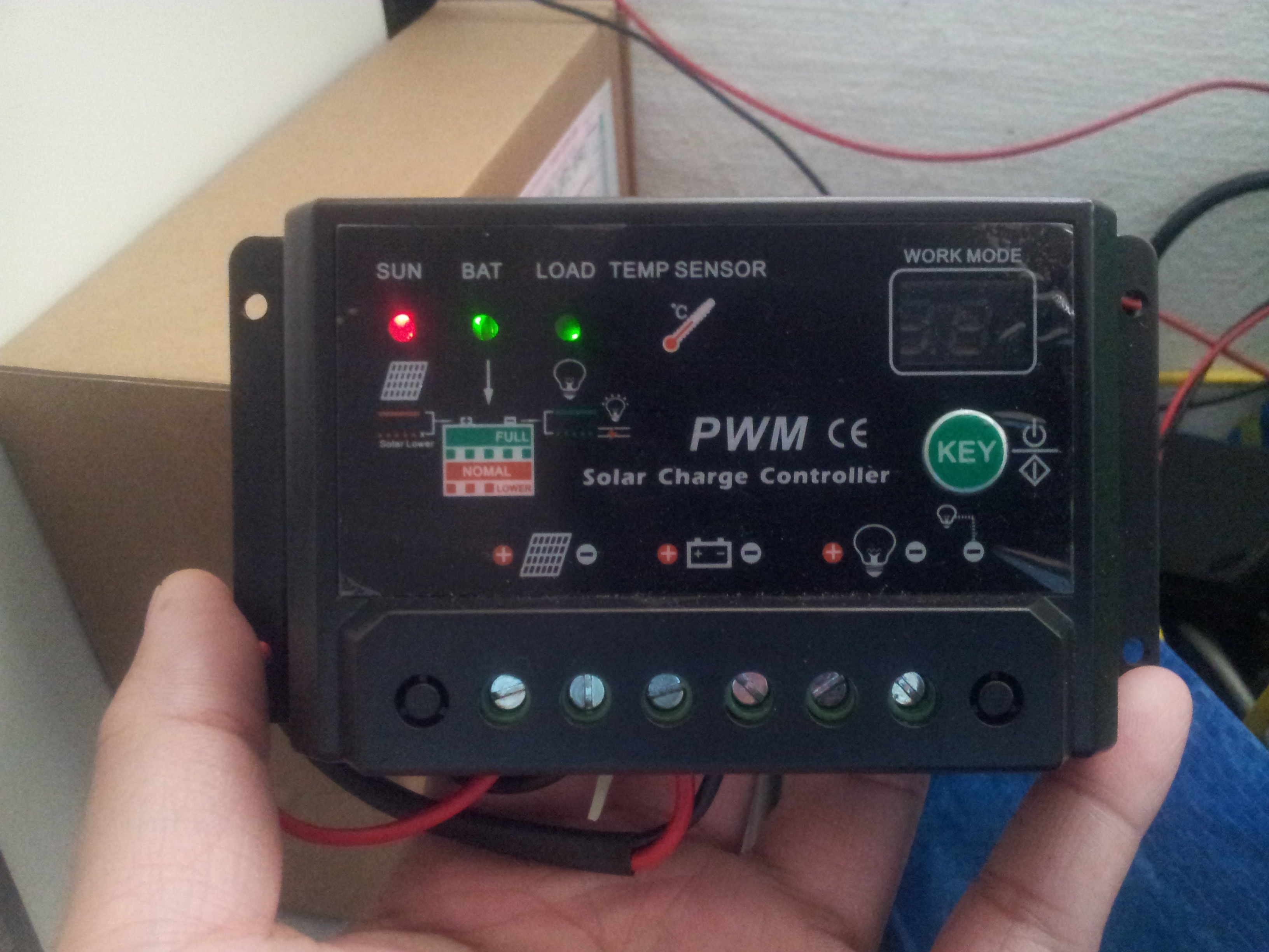
1. Power System - Definitely involves solar power. But also at the same time toying with the idea of harnessing the energy of the waves.
2. Propulsion and Station Keeping System - Good old motor and propeller pair. May also need a good way to effect position hold on the platform.
3. Communication System - Somekind of satellite modem. Probably will also include wifi, 3G/4G connectivity for high bandwidth data transfer near the coast. For long distance or inter-platform communcation maybe somekind of shortwave data modem.
4. Navigation/Collision Avoidance System - An onboard GPS for waypoint navigation. As big as the ocean is, subscribing to Murphy's law, the platform will inevitably collide into something. Maybe a pair of steroscopic camera for collision avoidance.
5. Auxiliary Sensors - I do not foresee there will be a space shortage on the platform. Possibly a suite of sensors can be included to monitor the weather (temperature, wind speed and direction, etc..., although I question the wisdom of putting a weather station on such a small platform) and the ocean (water temperature, salinity, etc...).
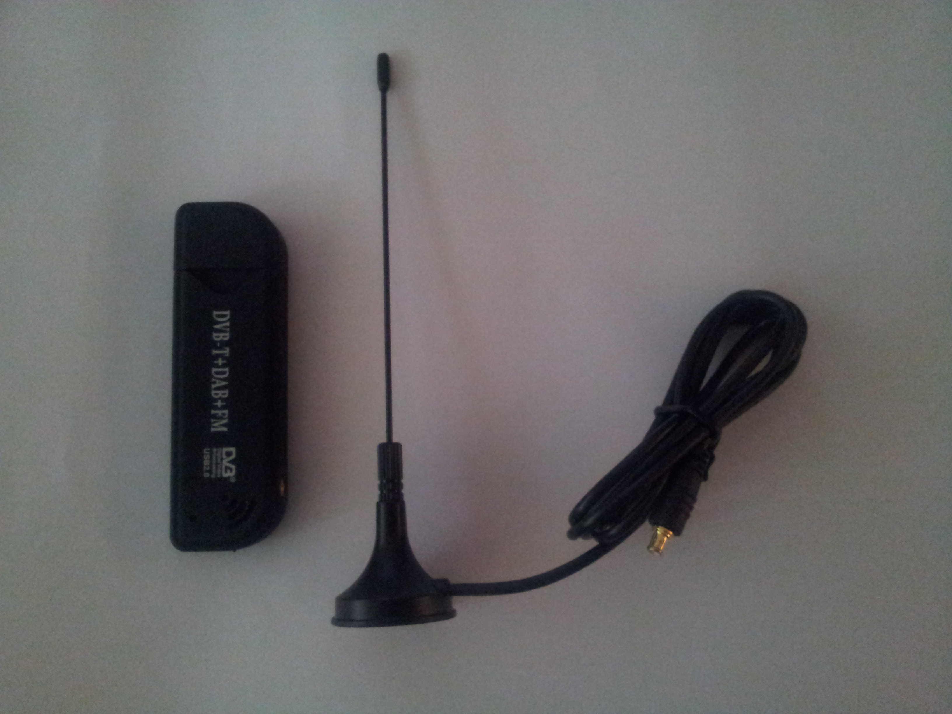
6. ADS-B Receiver - The...
Read more »

 Andy Osusky
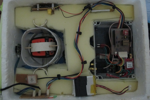
 Joseph Turner
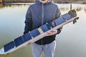
 Jianjia Ma
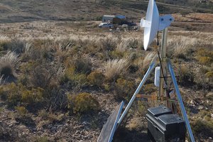
 tlankford01