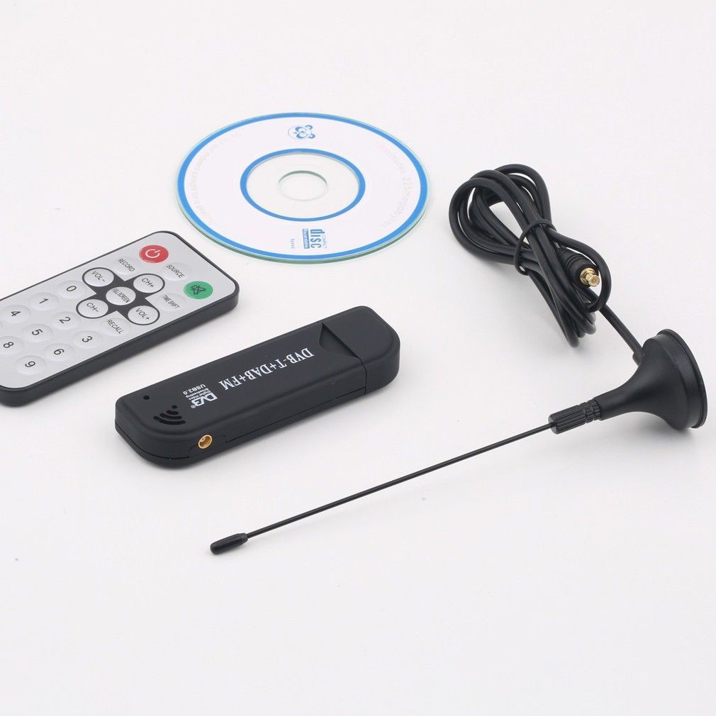
I think many would have guessed correctly that is a project log entry on the construction of an ADSB antenna. The digital tv tuner (shown below) a.k.a the ADSB receiver in the component list comes with a dinky little wire antenna with a MCX jack (more details on the tuner coming up in future blog). For antenna, bigger (up a certain length) is better, at least for this case.
An excellent guide for making your own ADSB antenna can be found here - http://www.balarad.net/
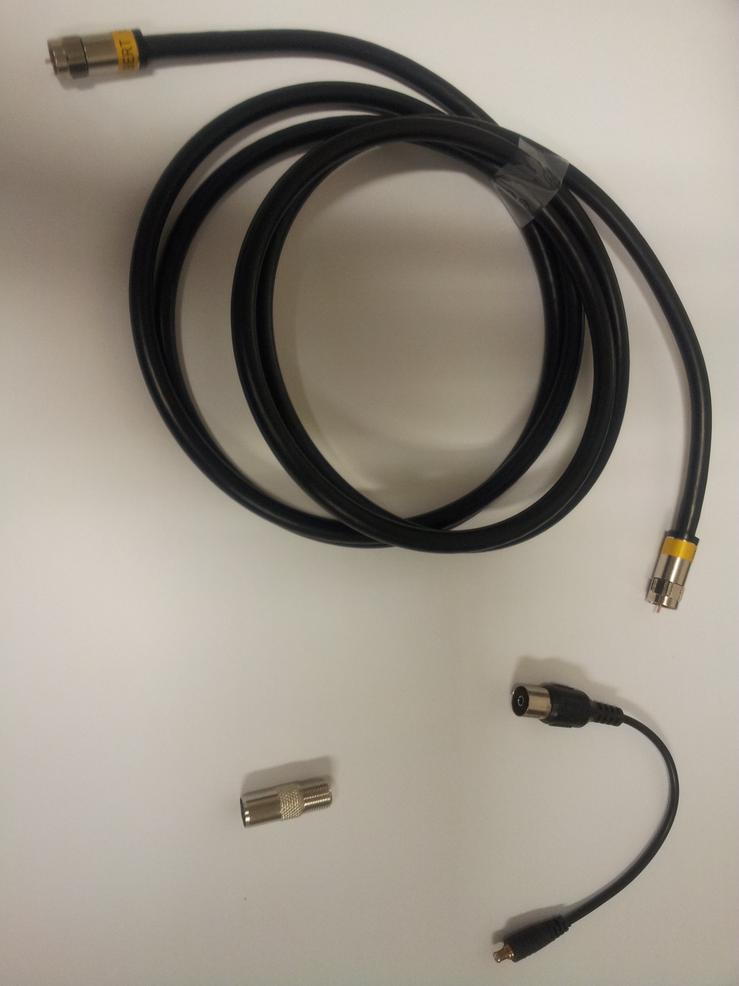
What I am actually building is called a Coaxial Collinear Antenna. The parts needed is a length (2m for my case) of 75Ohm, RG-6U coaxial cable (shown below, left)
Firstly I need to calculate what is the actual length each of the segments that I need to cut from the coaxial cable. The segments need to be half the wavelength of the received signal. Let's start from the fact that the ADSB signal is broadcasted on a frequency of 1090Mhz. So the wavelength is given by
wavelength = c/frequency where c = 299792458 m/s (this is exact) is the speed of light in vacuum.
Substituting a frequency of 1090Mhz in the above formula, we get the wavelength to be 0.275m. Thus half the wavelength will be 0.138m. Now this value of 0.138m is only applicable for the case for a radio signal traveling in vacuum. In an dielectric medium like in a coaxial cable, radio signal travels slower. This is a similar effect as in refraction as light travels slower in glass. Since the frequency remains unchanged, the wavelength must also decrease. From the datasheet of the cable, the 'Nominal Velocity of Propagation' is listed as 83%. Thus the magical length to cut the coax cable to 0.138 X 83% giving me 0.114m.
Now the next question is how many segment do I need? Ideally, the greater the number of segments, the more sensitive the antenna pickup is. Above a certain number of segments, the losses in the cable dominates and one no longer sees an increase in sensitivity. I believe in Hak5 they went for a 16 segment antenna here -
http://www.youtube.com/watch?v=zMoKs1eiyO4
For me the choice of the number of segments to use is based on a more mundane consideration. The antenna is supposed to be mounted on an ocean platform. So I would say antenna length of about 60cm is acceptable. Thus I went with a four segment antenna as a test.
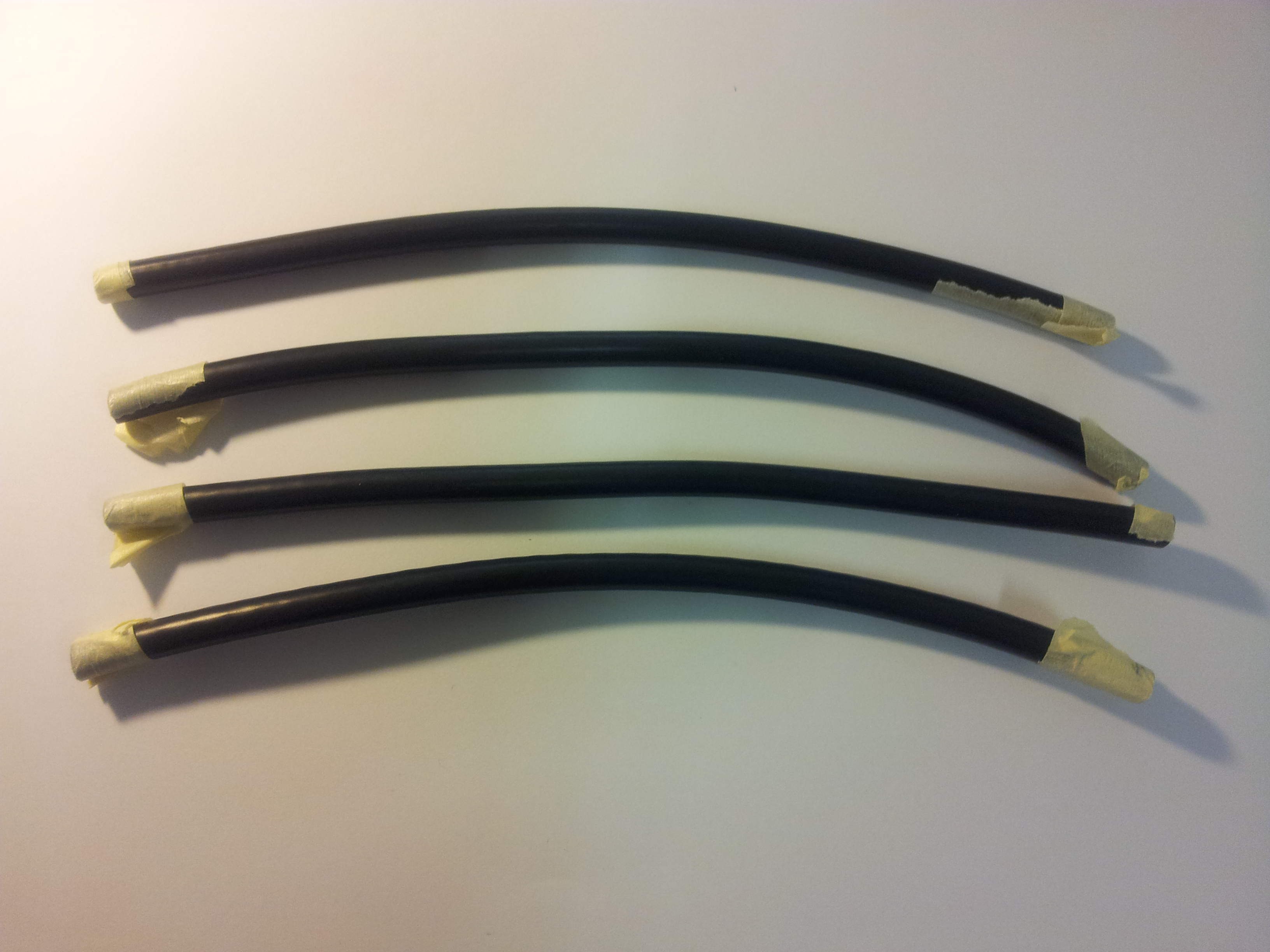
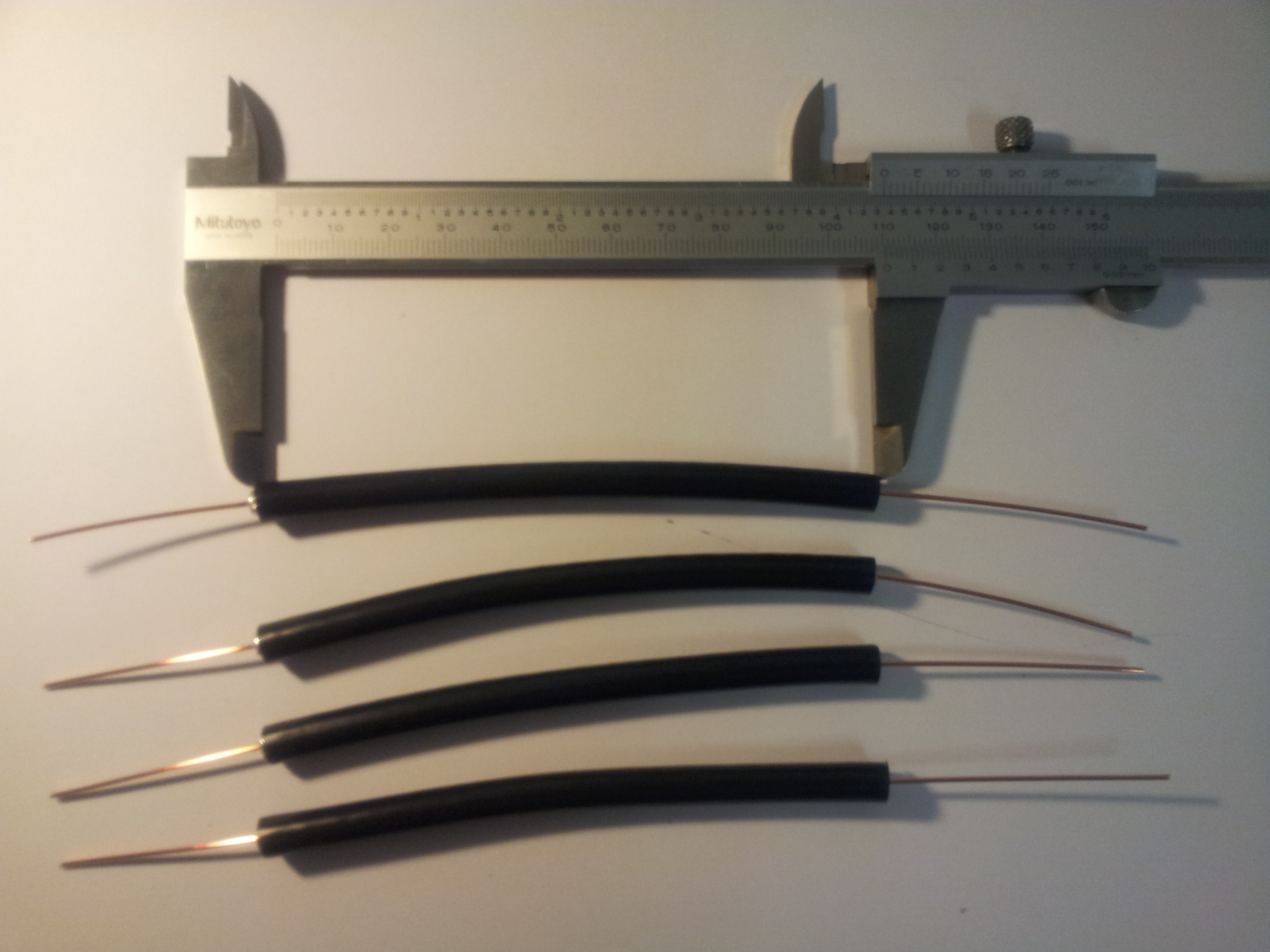
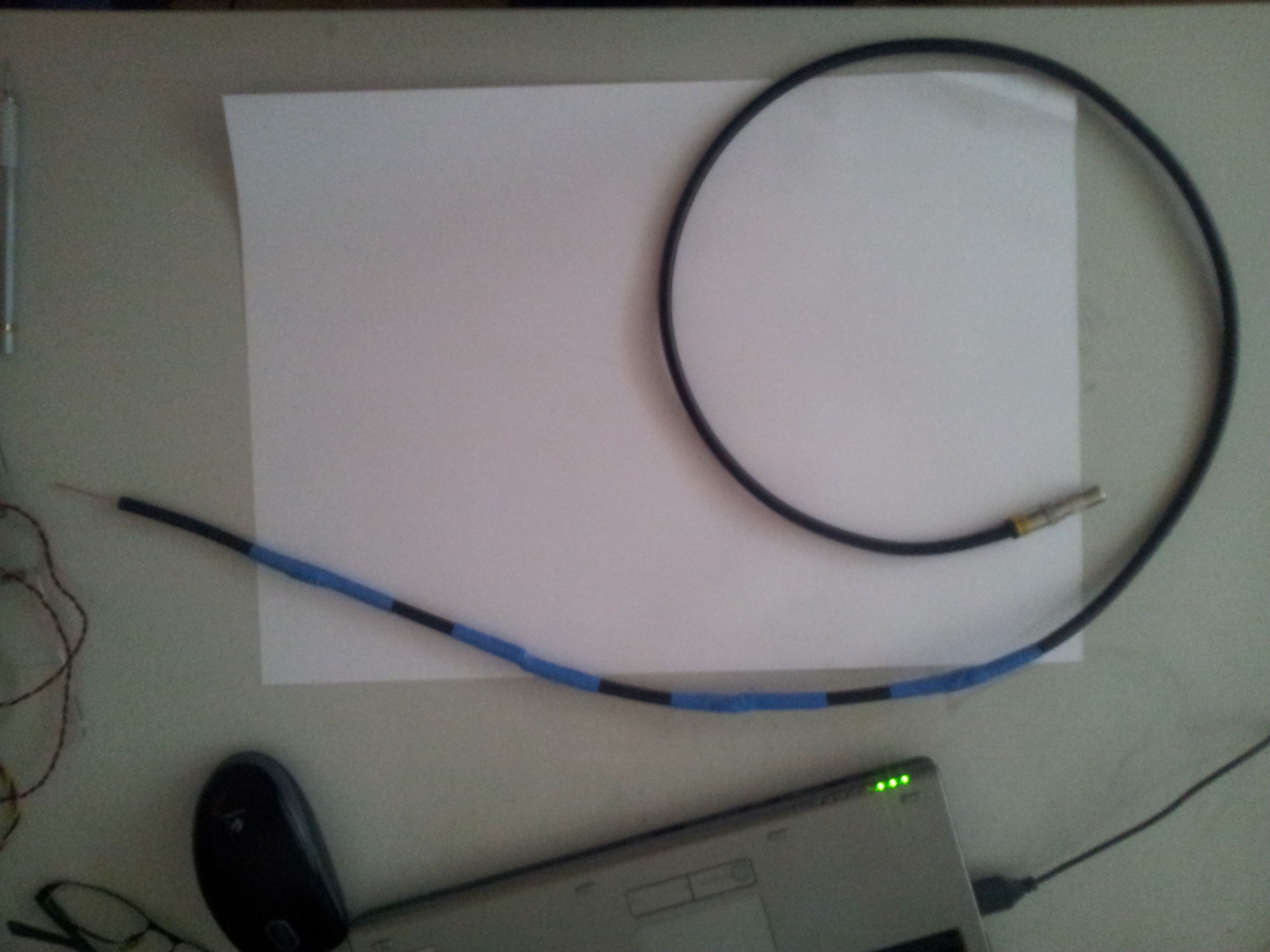
The antenna is assembled by inserting the core of one cable into the sleeve of the other. According to the balarad website, it is recommended to leave 5cm of the core uncut. With that consideration the length of each of the segment I need is 0.114 + 0.05 + 0.05 = 0.214m. With this number and my trusty vernier caliper, I commenced cutting. I have use marking tape on the cable to mark the places I need to cut. Result of this exercise is shown below.
I then stripped off 5cm of the outer layer leaving only the central core (shown below).
The core of each segment is then inserted into the sleeve of the other with electrical tape for insulation (shown below). The cables are then taped together with electrical tape.
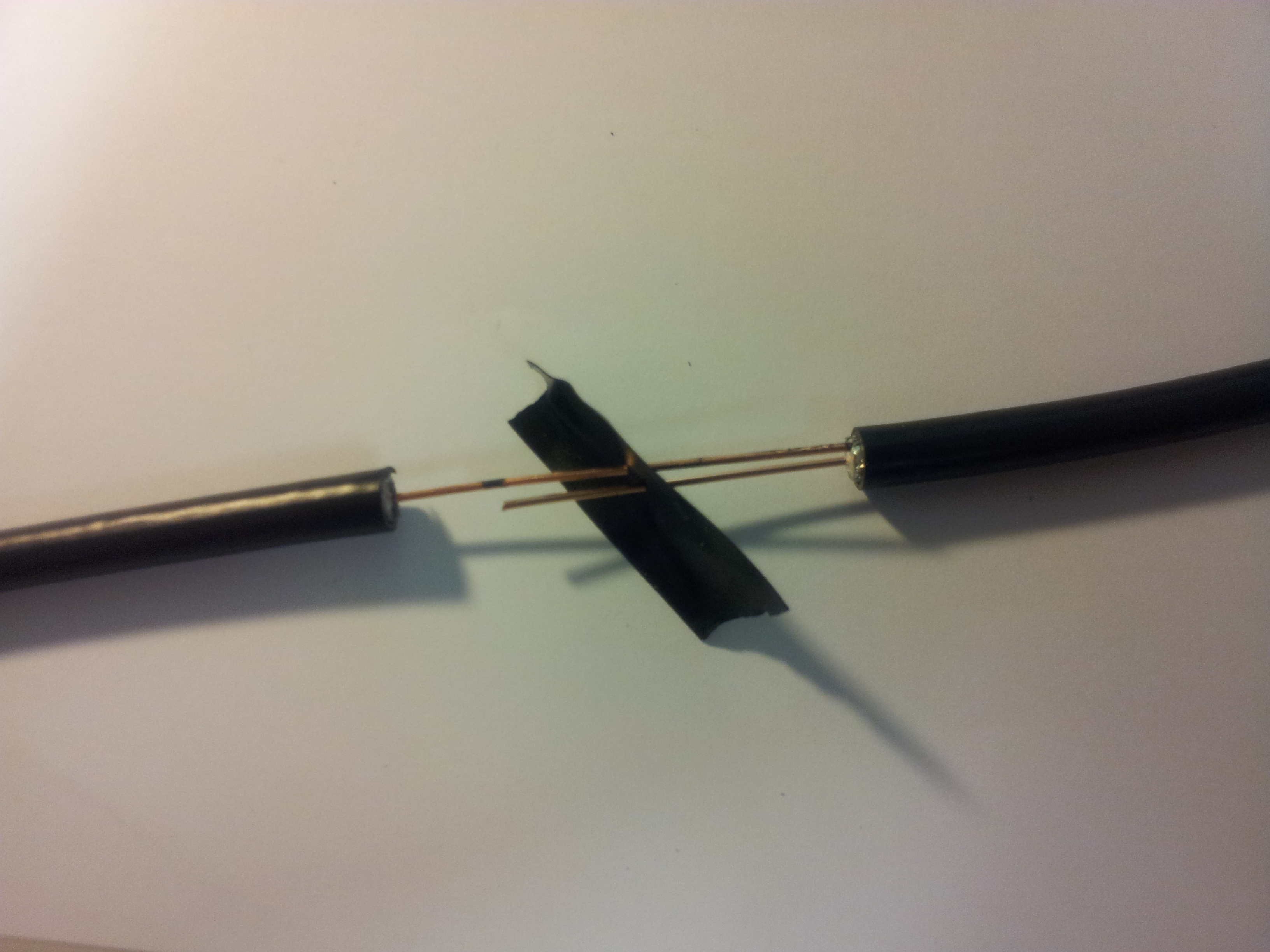
It seems that the recommended 5cm length for the exposed core is probably too long. The core have a tendency of perforating the sleeve of the other cable. So I would say a 2.5cm length for the exposed core would probably be sufficient. It is prudent to do a continuity check after every segment is installed. For every even number of segments, check for continuity between the core and sleeve on the opposite ends. For odd number of segments, check between the cores on the opposite ends and similarly for the sleeves. At one end of the cable I spliced in a patch of coax with the connector. With an application of heat shrink tubing, here is the final result.
However when I tried to characterize the frequency response of the antenna using a spectrum analyzer in the lab, I got an almost flat response. I strongly suspect that the connection between the tv coaxial connector and the BNC of the analyzer is bad (I was just hold them together with my hands). Will test cover more of this in the future. For the moment will test with the actual receiver I guess.
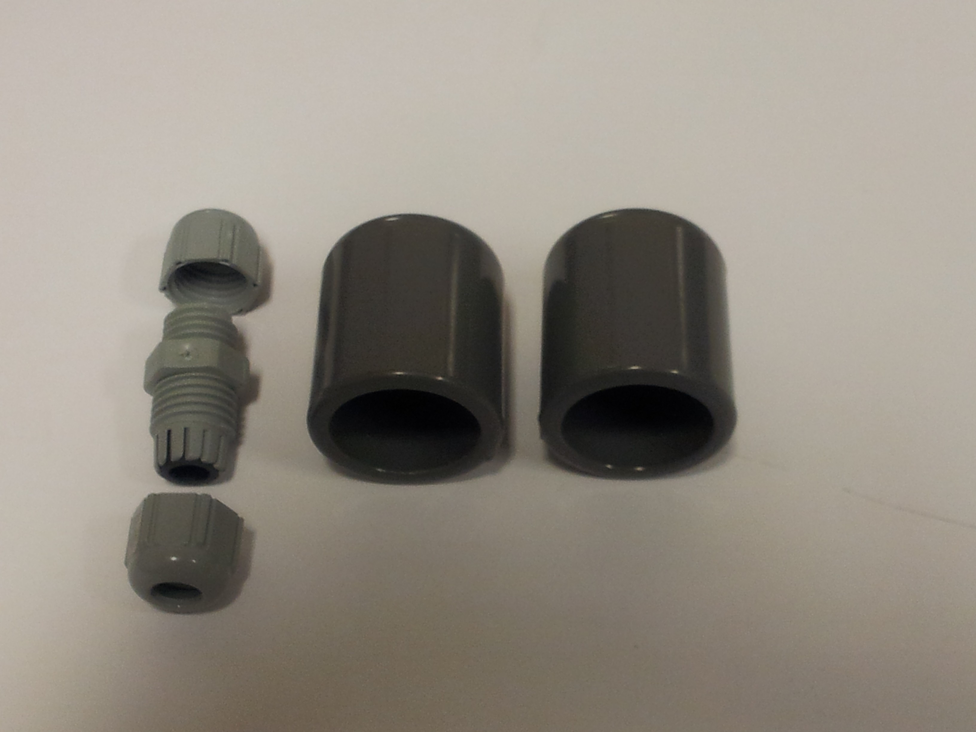
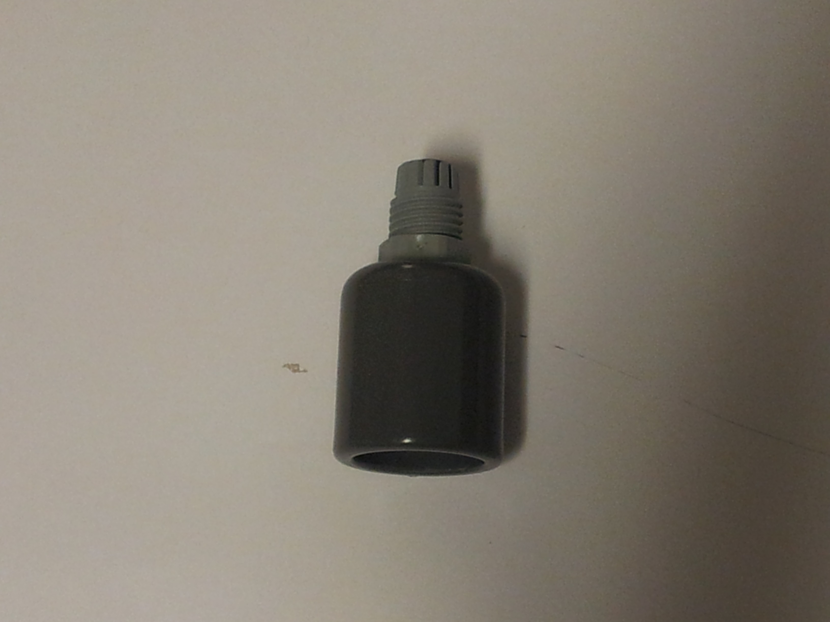
Next step is to put the antenna into a 16mm inner diameter PVC pipe for support. For that I also need two end caps (shown below, right) for the pipe and something call a M12 X 1.5 cable gland (shown below, left).
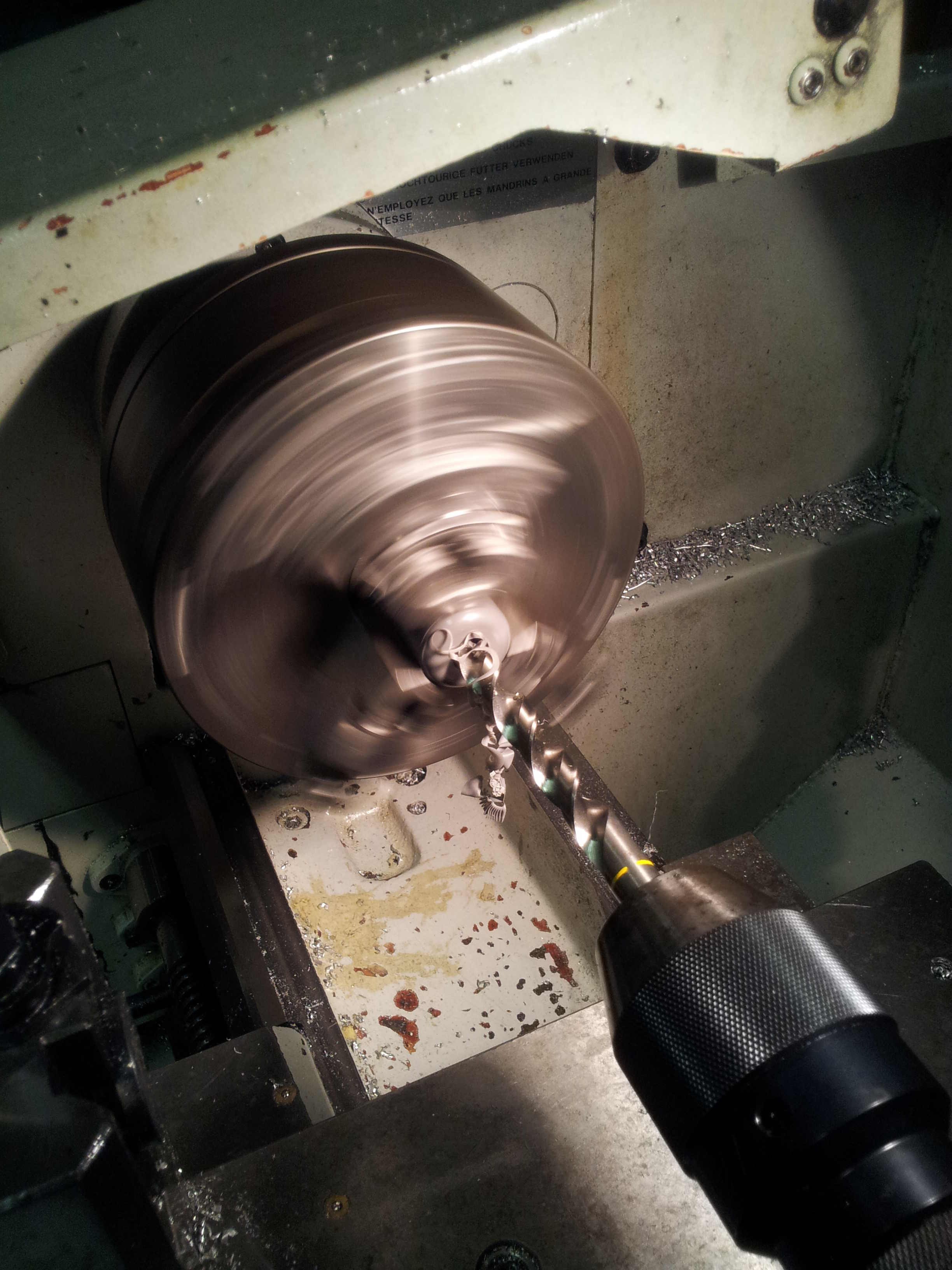
 The cable gland gives a water proof feed through for a cable through a panel. I then drilled a hole in one of the end cap for the cable gland (shown below). Was too pedantic about get the hole exactly centered so went ahead and used a lathe instead.
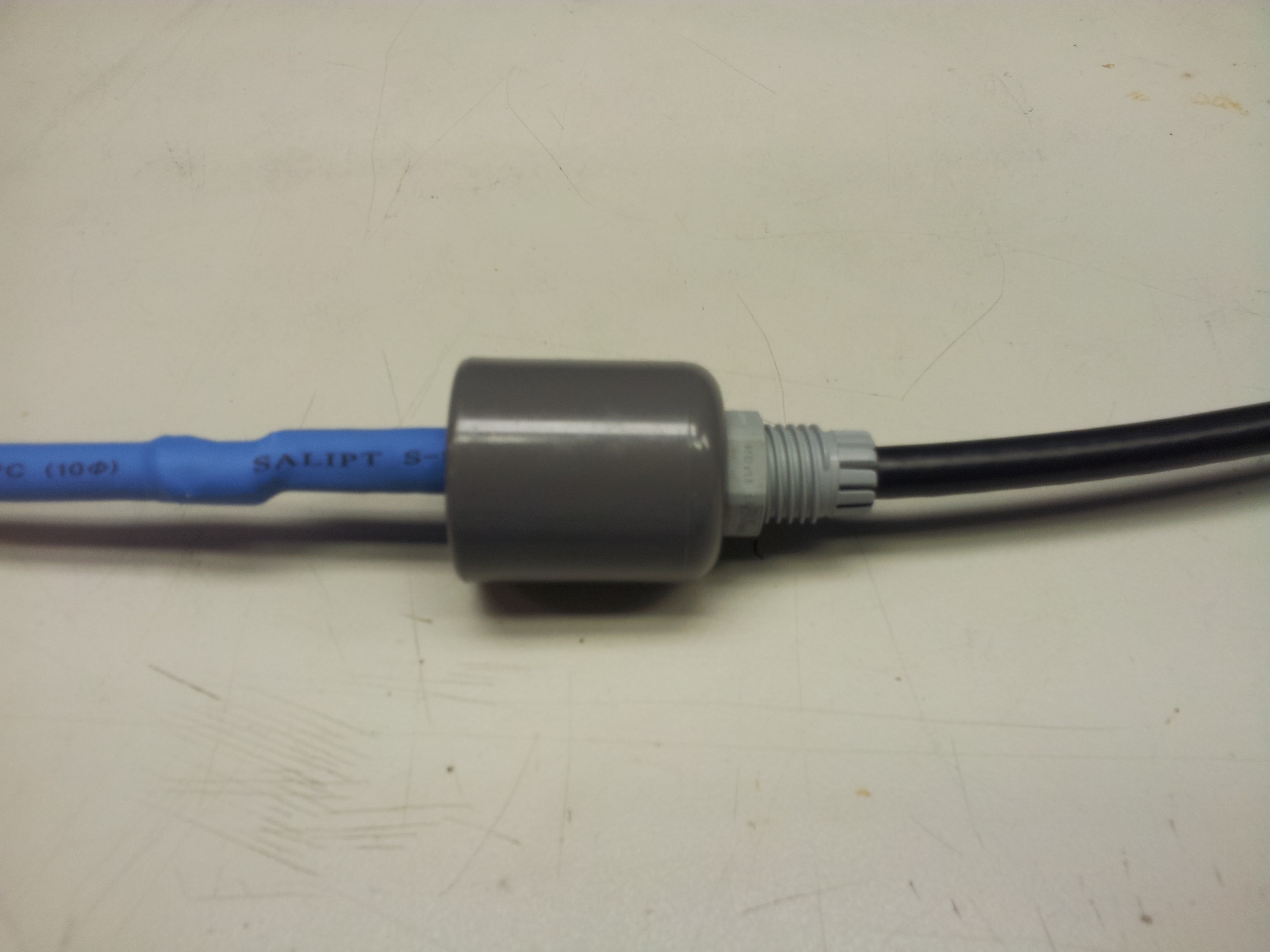
I then PVC glued the cable gland into the end cap (shown below). The end cap is simply too thick to use the accompany nut for the cable gland.
Here is when I realized I have made a mistake. With the antenna assembled, it is too big to be inserted through the cable gland. So I need to remove the last section of the antenna, thread it through the cable gland. The result is this -
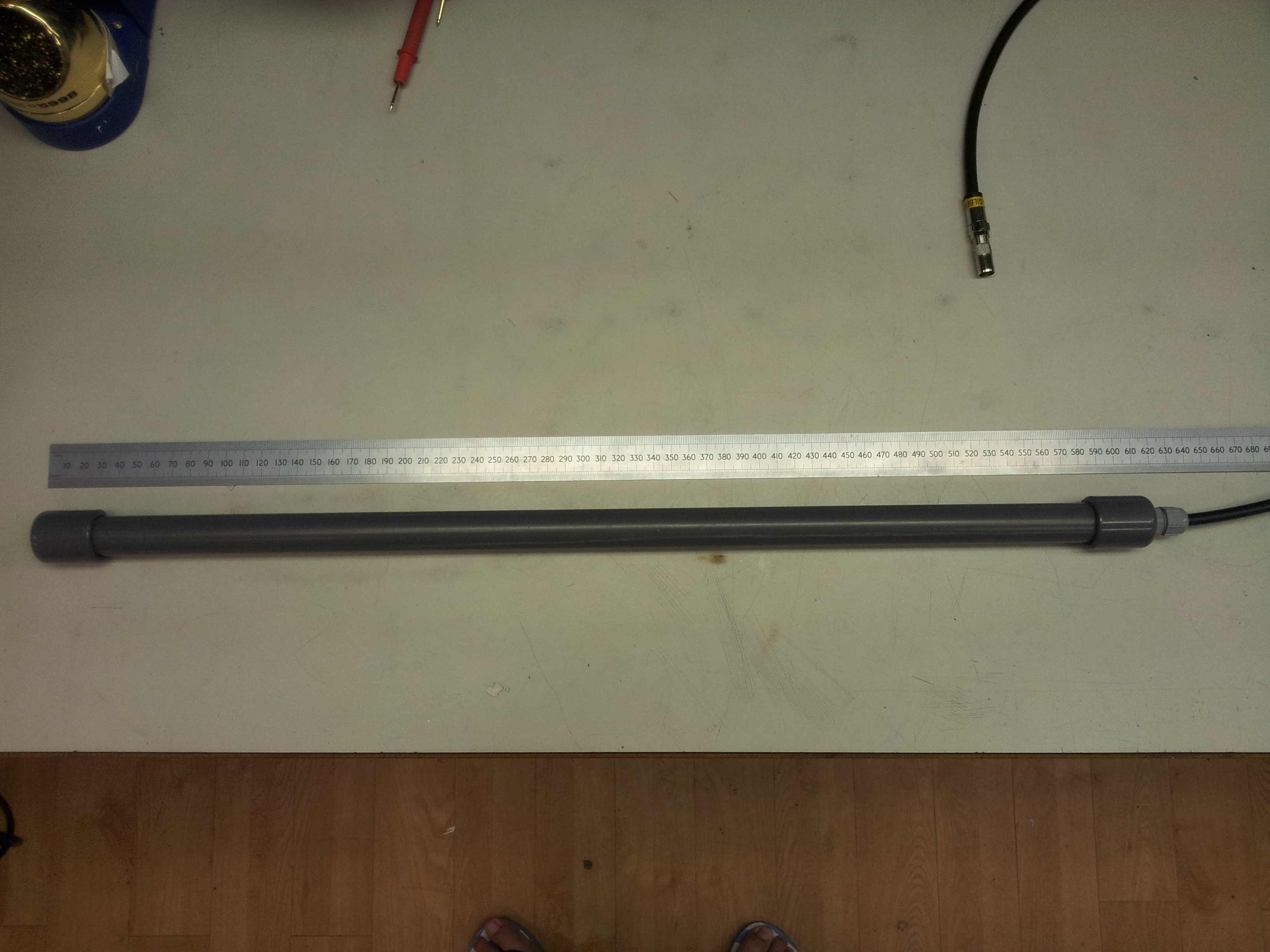
I then cut a length of PVC pipe approximately 60cm long, PVC glued on the end cap at the end without the cable. The other end with the cable I just press fitted it. Probably need to remove it in the future for some modification. Here is the finished product -
Discussions
Become a Hackaday.io Member
Create an account to leave a comment. Already have an account? Log In.