 Marius Taciuc
I'm posting today an LTspice simulation of the buck converter. I went for the simulation because it is always a better way than to try to change physical values of the components and try to remake the tests and measurements.
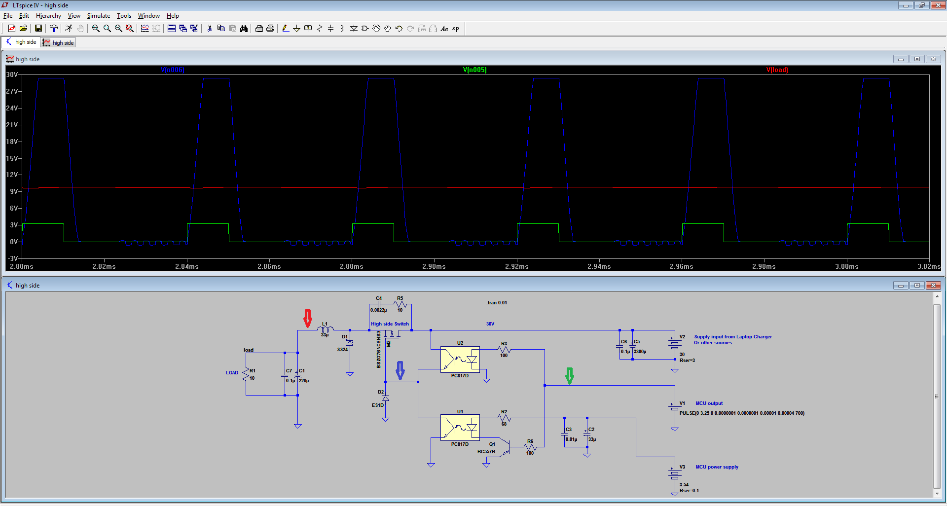
I might go for this variant of the Buck module, so I must integrate it into the larger schematic. Don't mind the actual value of the mosfet. I just used whatever I could find in the list that matched the characteristics of the IRF3205 (the one I'm planing to use). The simulation showed that I obtain better results with a 33uH inductor. It also reveals that increasing the current through the optocoupler LEDs I can obtain stiffer slopes. The simulation measures a maximum slope of around 2.5us instead of up to 10us per rising slope in the A2 iteration of the schematic. Much better!
I think this optocoupler approach in trying to build a mosfet driver for a high side switch is not the fastest one, but it surely is a cheap and reliable one. The D model of the 817s is the fastest one and it seems like with this schematic, the on-off switching times are just enough to make the optocoupler transistors NOT open in the same time.
I would call this the A3 iteration of the schematic after I integrate this module into the large schematic.
I ran the simulation at a PWM frequency of 25KHz, just above the audio band. A drawback of this actual design is that I cannot go higher because of these slopes.
At this point of the design, I'm wondering about the efficiency of the entire schematic.
Stand by for updates.
Discussions
Become a Hackaday.io Member
Create an account to leave a comment. Already have an account? Log In.