 Eugene Carlson
The first order of the day is to design a landscape irrigation controller and incorporate an integrated WiFi module. There are a number of WiFi topologies available, but the preferred is the Serial Peripheral Interface (SPI) connected modules. I prefer this as the interconnection to the PIC micro-controller which will make up the controller's central "processor".
The controller is built into a weather resistant enclosure that is capable of being mounted outside or in a marginally sheltered area. The controller will be installed in an area in which a good WiFi signal can be emanated to the outside public. This usually is outside.
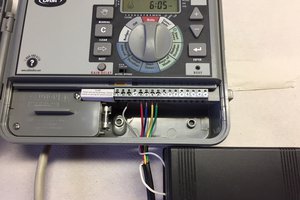
A standard WiFi and router installation will make the connection to the Internet and directly to the public. Communication will be made to the controller through both the internet and public WiFi.
The public participant will use a SmartPhone or other Internet/WiFi enabled device. The exact method of communication and user interface needs to worked out. The participant will need to be educated beforehand to recognize a water waste condition and respond through the connected device. The participant may be an employee of the company using the controller, a city worker briefed in the use of the device, a resident at an apartment complex that uses a controller, etc. This public education is a work in progress.
A system or level of permissions needs to be established. The controller user may allow a passerby to leave a message saying the sprinkler head is now a fountain or the city may allow any of its workers to shut the system off with subsequent notification of a supervisor. The controller user would determine which permissions are appropriate and allow them accordingly.
There is a grand opportunity for open source software development with devices as described here connected in such a manner. I can envision a person walking, riding or driving down a street and, seeing something in the environment with which they wish to interact, pulling out an enabled wireless device and doing so. (If you think this a new and wonderful idea I would reference as a precaution to unbridled optimism the movie "Forbidden Planet" from the 1950's. There may very well be nothing new under the sun.) In addition to water waste control there are many other applications yet to be defined.
This is the text portion of the system design document. The document is in .pdf format and available on request. (There appears to be no way to make .pdf documents available in this project page.)
Landscape Water Waste Elimination
System Design Document of 20 Aug 2014 - Page 1 of 3:
The LIC portion of the project is very straight forward and of conventional design. Possible the only not so conventional addition is the WiFi module which is connected via a Serial Peripheral Interface (SPI) port to the LIC micro-controller. A conventional system was chosen because it is well established as a design. The "leading edge" of this project lies in the enabling of the communications between a person in the street who notices an abnormal water flow condition and the device controlling water flow.
Several control units of this design by this designer have been placed in the retail customer market. The design from the schematic and PCB perspective is considered working. The reason for a new schematic and PCB rendering is to avoid any possible conflict with past proprietary designs. What has not been proven is the incorporation of the WiFi module. This WiFi module is the next step toward improving the function of the LIC design.
There may be third party concerns such as patents and parts supplies issues. These will be addressed as the design proceeds. Any patent issues will be noted but the development will proceed toward a commercial version while these issues,if any, are considered. The parts supply issue will be given design consideration as the project parts are specified.
Editor's note: LIC is the "Landscape Irrigation Controller" it is initially identified in the pictorial...
Read more »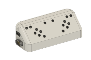
 Julien OUDIN
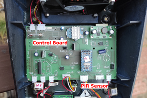
 RemoteMCU
 Alec
Alec