 Myrijam
For the technical development and construction of our Venenfinder, we follow the principle that appears most useful after our experiments and literature research: The skin is irradiated by an infrared light source, while a camera (Pi camera or webcam) records the reflected light. The camera image is then processed using mathematical filter algorithms.
However, most cameras have a filter to block infrared light, so we either have to use one that doesn’t or convert a normal webcam by removing the blocking filter. The single board computer we use for image processing is the Raspberry Pi3 (inexpensive, powerful and available worldwide). There are two cameras that can be connected directly, one with and one without IR-blocking filter. Using the "Raspberry Pi NoIR Camera Module" saves you from disassembling a webcam and modifying the hardware – with this module you can build the Veinfinder using mostly off the shelf components, which makes it easier to rebuild for people with less experience in hacking playing with technology.
If you look at the spectral sensitivity of the Raspberry camera module (Fig. XYZ), you can thee three peaks in sensitivity (surprisingly at blue, green, red) and a slight improvement of sensitivity again when approaching the near infrared wavelength again:
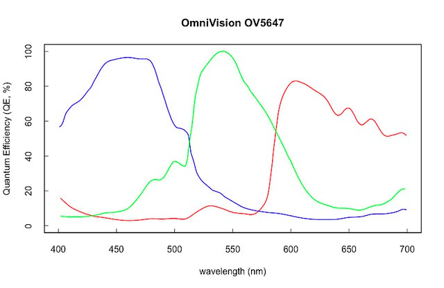
Figure 7: Spectral sensitivity of the Raspberry-Pi camera sensor
(Type designation of the image converter OmniVision QV5647)
Source: https://github.com/khufkens/pi-camera-response-curves)
Image sensors have "sub-pixels" per image pixel, which react particularly sensitively to different wavelengths in the visible region and enable an image reproduction, as we expect it to be from our perception. However, the spectral sensitivity of all three sub-pixels increases again in the NIR range; In the graphic, this is already recognizable for blue- and green-sensitive image receptors. Thus, the initially paradoxical situation may appear that in the infrared region (NIR), the "blue" subpixels reproduce the reflected infrared radiation very clearly (and darken the veins due to the absorption), whereas they are unsuitable for venous localization in the visible region.
Here is an estimation of sensitivity for an extended wavelength:
Figure /XYZ:
Either way, it becomes evident that you should add a different filter that blocks everything but IR light – the easiest way to do so is to use a piece of of exposed analog film.
Buildlog 2: Raspi-Cam Version
Version 1: Standard Camera System (Pi-Camera)
The first version uses an off the shelf camera system, the Raspberry Pi NoIR Camera Module. It is connected via a relatively rigid flat-ribbon cable, which reduces the possible applications. For this reason, we have integrated two adapters that physically moves the pins of the Raspberry camera adaptor to an HDMI-port and vice-versa. The adapter can be bought from Tindie (https://www.tindie.com/products/freto/pi-camera-hdmi-cable-extension/).
It is simple a physical conversion that uses a standard HDMI cable for more flexibility and more length than the ribbon cables provide; there is no signal conversion – so don’t confuse this port with the HDMI output from the Raspberry :-)
Illuminating the skin and tissues is done by a self-made headlamp consisting of a matrix of 9 high-performance infrared light-emitting diodes. They are arranged in a 3x3 arrangement with reflectors and are controlled by standard constant current driver for 12V. During our experiments we designed, 3d printed and tested several housings for the camera module as well as for the headlight:

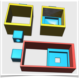
Figure 10: Construction of camera housings and IR headlights with reflectors
Overall, however, this arrangement was not stable and user-friendly enough and the filter made of exposed film, which passes IR light and blocks visible light, could not be well accommodated. As a next stage we have therefore designed a housing that can be screwed to a mini-tripod and integrates all necessary components. The filter can be attached with a plate with magnetic support:
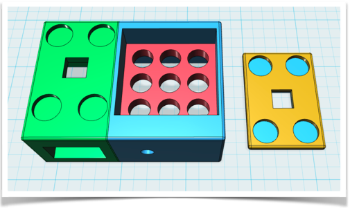
Figure 11: Overall construction - green: case for camera, blue: case for LED matrix spotlight, red: mounting plate for the 3x3 LEDs , orange: snap-on attachment for the filter.
The design is easy to replicate with any 3D printer. Strong magnets are pressed into the round recesses, which fix the filter in front of the camera lens. We use a Pitop Ceed as the basis for Raspberry and Display, but we designed a case for the Raspberry Pi computer together with a 7-inch display for the second approach (using a webcam) so that the overall system is as easy to handle as possible.
Discussions
Become a Hackaday.io Member
Create an account to leave a comment. Already have an account? Log In.