 kodera2t
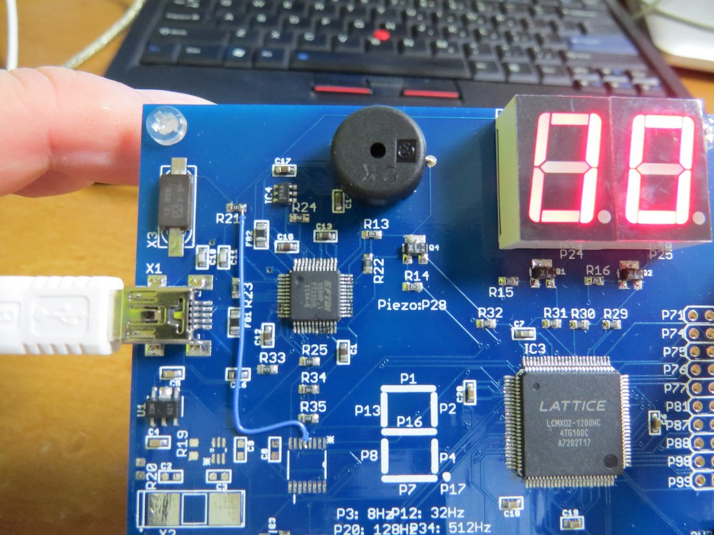
The FPGA board has a piezo sounder connected to P28 of MachO2 through transistor buffer. This time I did a quick check of it by "fast switching" GPIO of FPGA. Still this FPGA is working as a I2C GPIO extender and controlled by Arduino, but also FPGA standalone sound application will be possible...
The Arduino source code (controlling I2C implemented in FPGA) is as follows:
#include <Wire.h>
int sevenseg[10]={
//abcdefgD////negative logic
0b00000011,
0b10011111,
0b00100101,
0b00001101,
0b10011001,
0b01001001,
0b01000001,
0b00011011,
0b00000001,
0b00001001,
};
/////////////////////////////////////////
void setup() {
  Wire.begin();//starting I2C of Arduino
///activating GPIO of Lattice//
  Wire.beginTransmission(0x09);
  Wire.write(0x06);
  Wire.endTransmission();
//////////////////////////////
}
void loop() {
  for(int i=10;i>=0;i--){
  display_LED(i);
  if(i==0){
    sound(3);
  }
  }
}
void display_LED(byte num){
  for(int i=0;i<40;i++){
  byte fstdig_reg=0b11111101,secdig_reg=0b11111011;
    byte secdigit=num/10;
    byte fstdigit=num-secdigit*10;
    dig_select(fstdig_reg);
    Wire.beginTransmission(0x09);
    Wire.write(0x01);
    Wire.write(0x00);
    Wire.write(sevenseg[secdigit]);
    Wire.endTransmission();
    delay(8);
    dig_select(secdig_reg);
    Wire.beginTransmission(0x09);
    Wire.write(0x01);
    Wire.write(0x00);
    Wire.write(sevenseg[fstdigit]);
    Wire.endTransmission();
    delay(8);
}}
void dig_select(byte reg){
    Wire.beginTransmission(0x09);
    Wire.write(0x01);
    Wire.write(0x01);
    Wire.write(reg);
    Wire.endTransmission();
}
void sound(int repeat){
    for(int j=0;j<repeat;j++){
      for(int i=0;i<1000;i=i+2){
    Wire.beginTransmission(0x09);//select 0x09
    Wire.write(0x01);//"write GPIO" command
    Wire.write(0x01);//select GPIO_1
    Wire.write(0b11110111);//write GPIO1_3=0 (P28=0)
    Wire.endTransmission();
    delayMicroseconds(i);
    Wire.beginTransmission(0x09);//select 0x09
    Wire.write(0x01);//"write GPIO" command
    Wire.write(0x01);//select GPIO_1
    Wire.write(0XFF);//write GPIO1=0xFF (P28=1)
    Wire.endTransmission();
    delayMicroseconds(i);
    }
    }
}
Indeed, this is not FPGA training but just writing Arduino sketch but surely confirmed its "sounding" Actual operation can be seen in the following movie..
Discussions
Become a Hackaday.io Member
Create an account to leave a comment. Already have an account? Log In.