The read head of the project will consist of a pair of photodiodes that will read the pattern on the codestrip and output a quadrature signal to the microcontroller. As the readhead passes over the codestrip, each photodiode will transition from a LOW to HIGH state and back again. Since the photodiodes are offset half a feature width from each other, the position resolution becomes effectively double the codestrip resolution. Through the quadrature technique - monitoring what diode is rising or falling and the state of the other diode - we can determine the direction the readhead is moving.
At this point I have made an example circuit diagram and started prototyping things on the breadboard. I can do the electronics prototyping concurrently with making the codestrip, and getting an earlier start on the electronics will enable me to find and fix any bugs or issues earlier in the process.
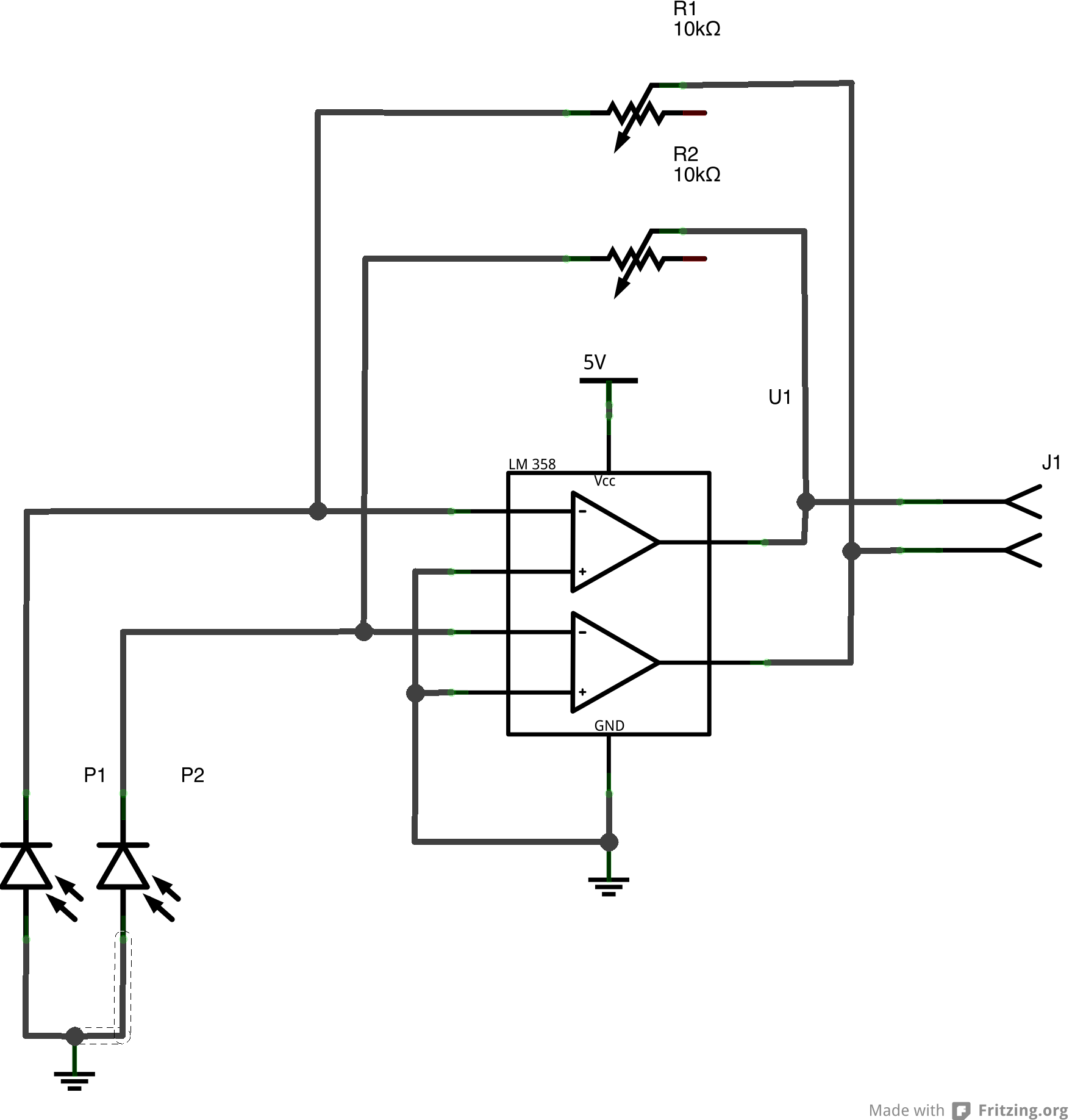
(Schematic Update: the 5v (now ground) on the photodioes was updated - that connection is to Vss)
The circuit is a simple photodiode amplifier - the photodiodes are reverse-biased and amplified by the op-amp. The trimmer resistor in the circuit will allow it to be tuned for various light levels and operating conditions. This trimming capability may not be necessary in the final design, but by having it on the prototype it allows quick testing and recalibration without having to be constantly swapping resistors.
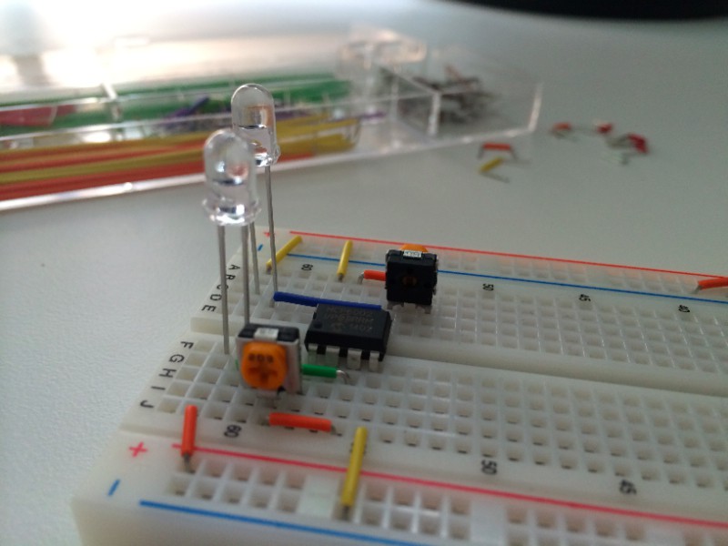
(The breadboard here is not yet fully populated, and the op-amp is a MCP6002, not the LM358 in the schematic. The jumper in the schematic will connect to the microcontroller.)
Discussions
Become a Hackaday.io Member
Create an account to leave a comment. Already have an account? Log In.