 Jon Klein
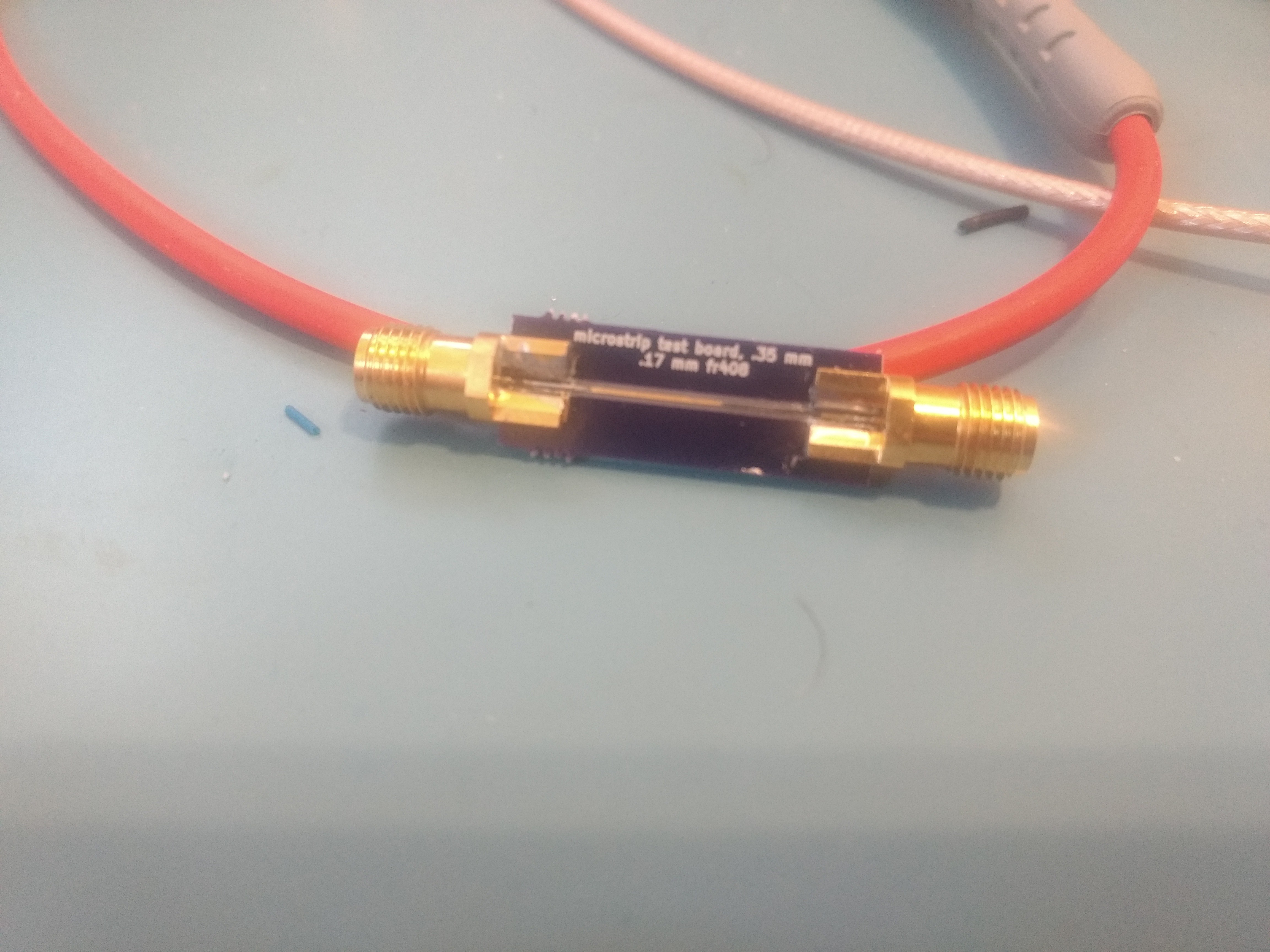
With two port measurements on network analyzer somewhat working, I created a small microstrip test board to evaluate a SMA connector footprint and transition to microstrip.
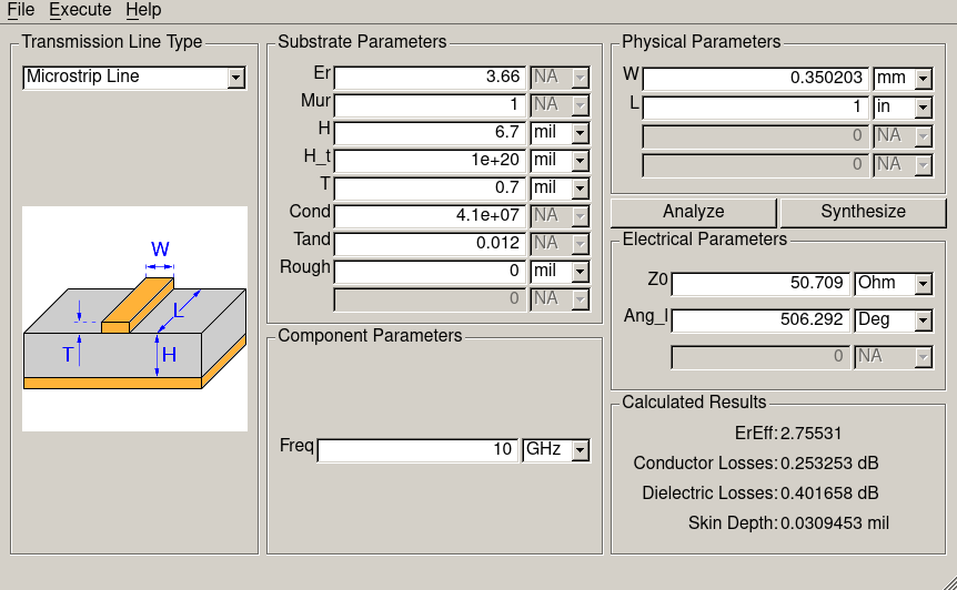
Here are (possibly incorrect) measurements of the test board from the network analyzer prototype: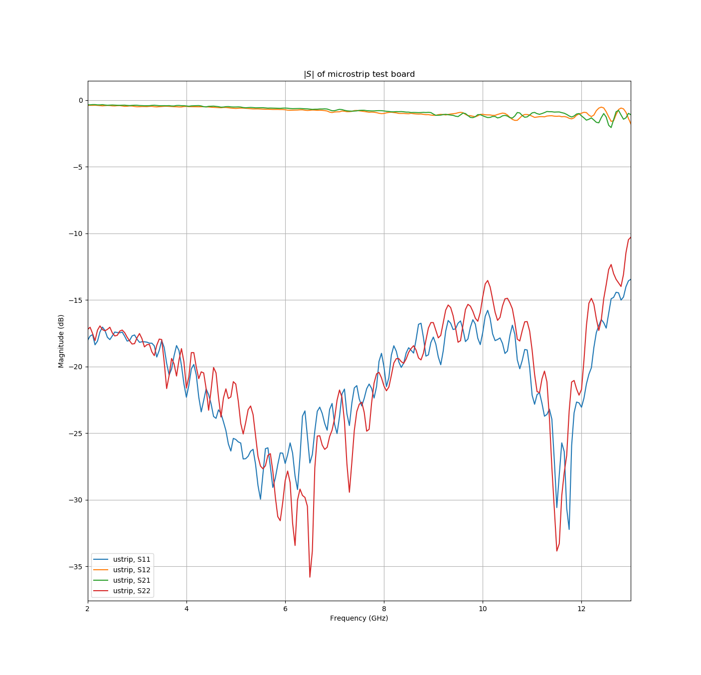 It looks.. okay. S21 at 10 GHz is about -1.2 dB, and S11/S22 are generally below -15 dB out to about 12 GHz. Running the OSH Park 4 layer stackup through the qucs line calculation tool, I would expect about .65 dB of attenuation through the microstrip. If that is correct, it leaves about .3 dB through each of the connectors.
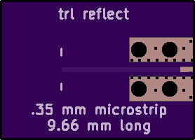
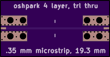
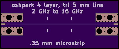
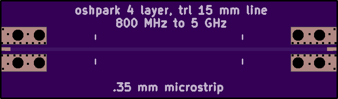
S11 and S22 aren't as low as I was hoping, but I'm not sure if that is from the microstrip or from the connector footprint. To separate out the microstrip testing from the connector footprint testing, I'm making up some TRL (thru reflect line) calibration test boards to extend the calibration plane of the network analyzer past the connectors. TRL calibration will also remove my dependence on an uncertain SLOT cal kit and make it easier to investigate if the ripple in my measurements is from incorrectly defined calibration standards or some other issue with the VNA.
I made a few modifications to the SMA connector footprint compared to the earlier test board to make assembly easier. The clearance between the microstrip and the ground pads is increased a little, and I added back in the soldermask to stop solder from wicking down the microstrip.
I'll post an update on the status of the TRL calibration in a few weeks once the boards arrive.
Discussions
Become a Hackaday.io Member
Create an account to leave a comment. Already have an account? Log In.
Any update on those measurements? I'm terribly curious!
Are you sure? yes | no