 Spencer
The frame was mostly complete after the last update but it still needed finishing. Here it is with shellac applied!
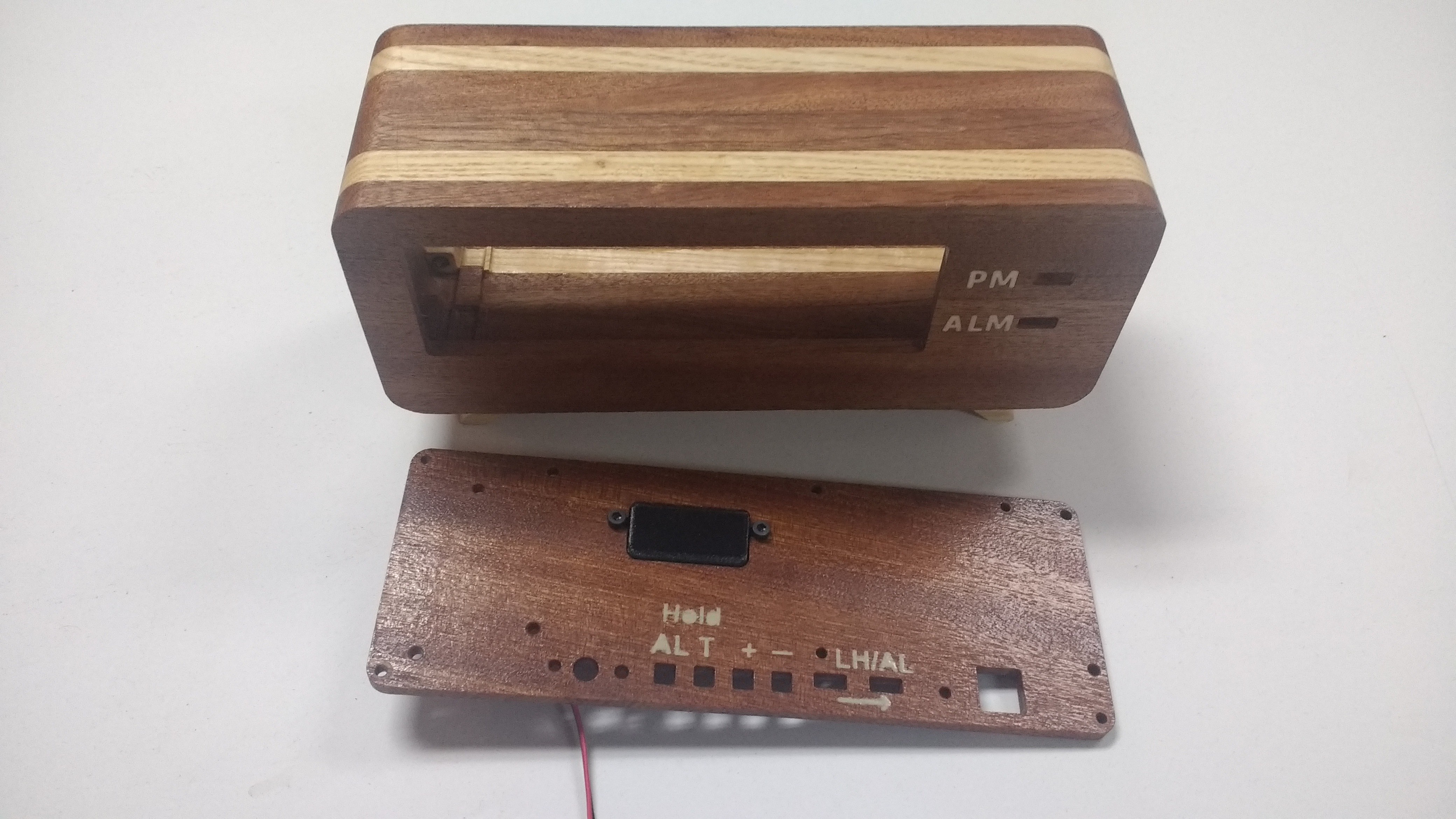
I'm loving the look! The sapele really pops! The text on the rear panel was made with a custom stencil. I machined the lettering out of 1/32 inch ply wood and used spray paint. It worked well enough. The black block is a holder for 4 LED's. This is for the sunrise alarm feature. The idea being that slowly making the room brighter starting an hour before the alarm helps you wake up.
Then next step after this is to wire the display module. It's going to be over 210 solder connections so I'd better get started. Here's what it looked like when I started. I'm glad I have the thin soldering iron...
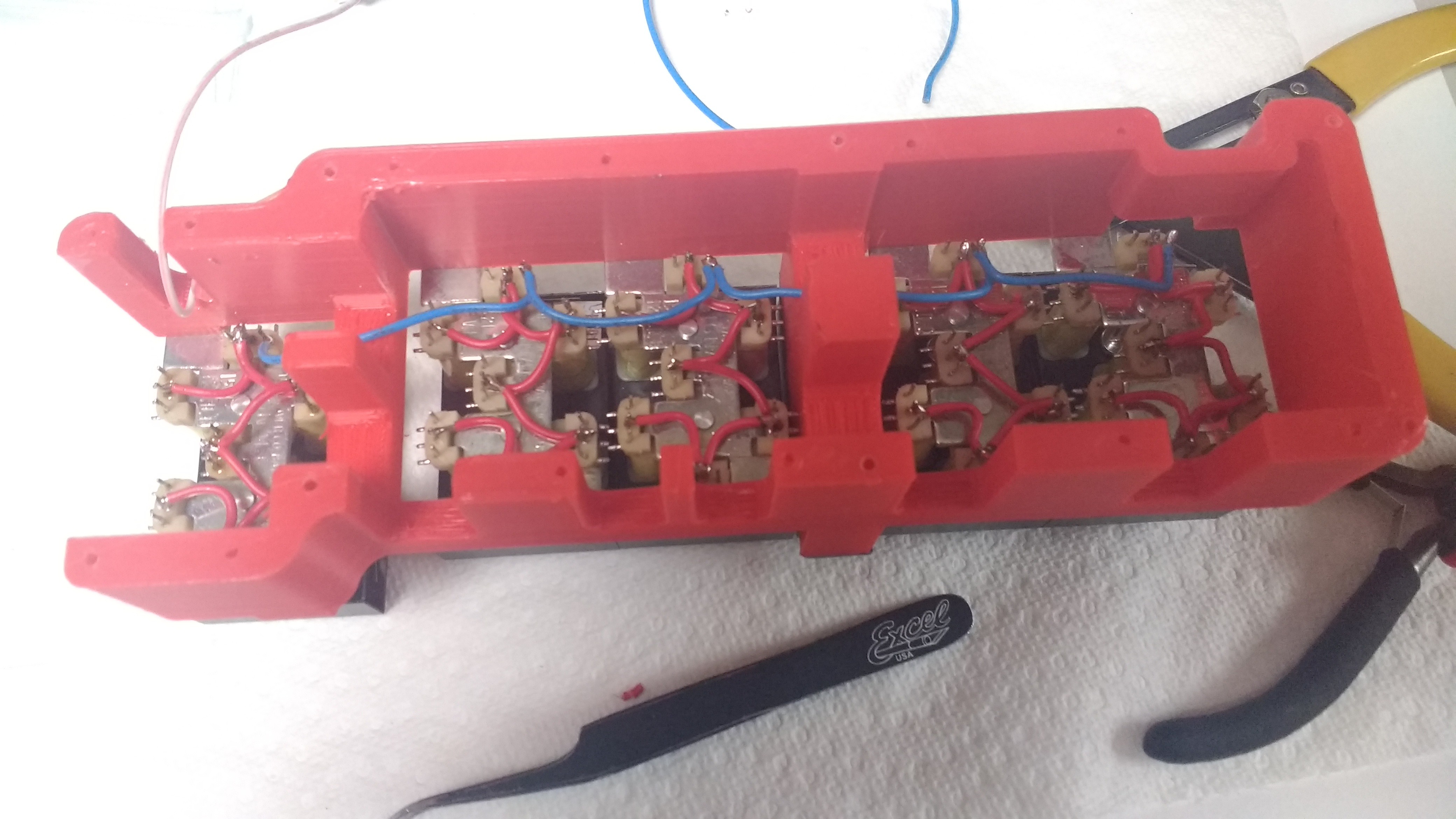
I have three sets of connections to wire up. The power/select lines and the enable. disable lines. After a few hours/days I had this.
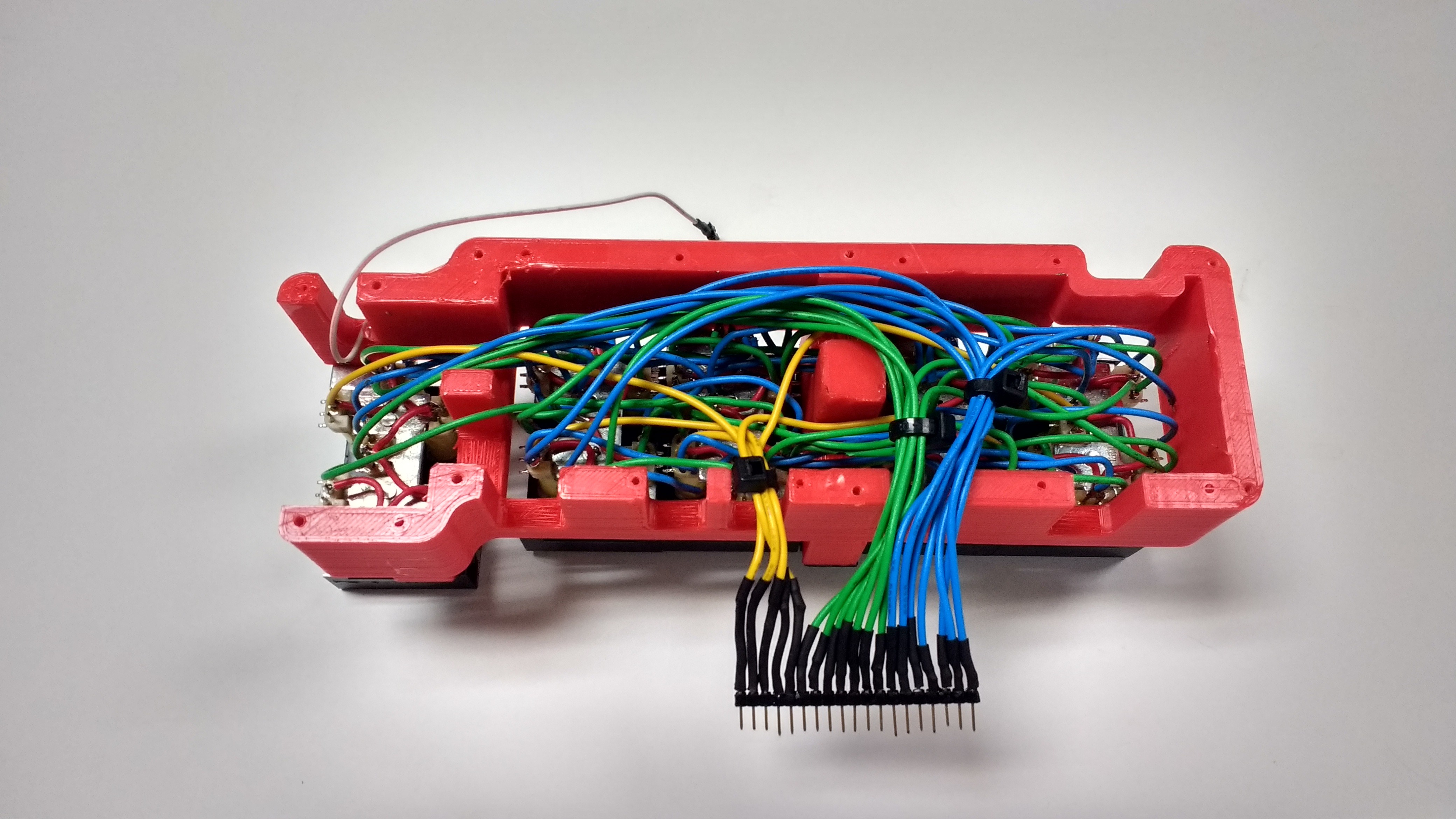
Alright now time to test it out! And it doesn't work wooo! Surprisingly enough it's not a wiring error just a core driver design error. Here's a short explanation with a diagram.
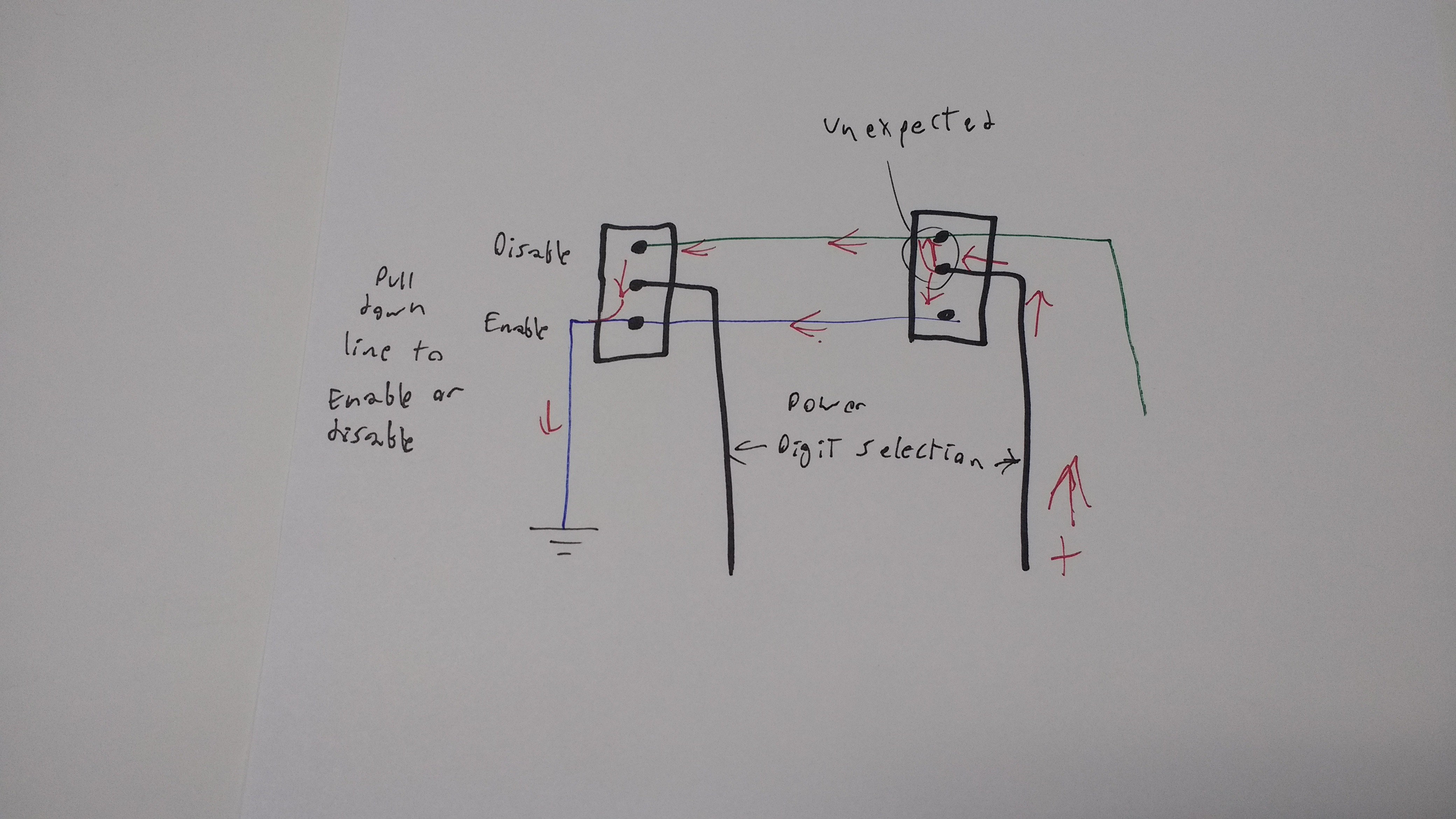
Each display has 7 segments. Each segment has 3 wire controlling it. The middle connection is power and the outer connections are disable and enable. I wired all the power connectors on each display together and I can select the display by driving only 1 of 5 drive wires. I can control is it's enable or disable by selecting the enable or disable line and driving it low. All the enable and disables for each segment are linked together.
The issue is if I drive segment 1 and pull down the enable line on segment A then the current travels through the enable wire. However it also travels through the disable line and then though each digit on the other segments. This will set segment A on all the digits to enabled.
I can fix this with 60 diodes but I don't have room to have the free floating in the case. I will need an adapter PCB.
I plan to do this with an adapter PCB soldered directly onto the digits that will contain the diodes. It will be more reliable than the mess above. The wires do have a certain charm to them... I will miss that horrible mess.
Discussions
Become a Hackaday.io Member
Create an account to leave a comment. Already have an account? Log In.