 Spencer
With the schematic complete the next obvious step is PCB creation and you will not be disappointed. (Don't be disappointed)
The PCB was fun to work on. The limiting factor was the size of all the switches and buttons on the back. I only have 6 inches to work with and it came out to about 5.4 inches. They also take up most of the space on the PCB. Fitting the driver circuit in was tight. Not as tight as my BCD decoder but it was "interesting"
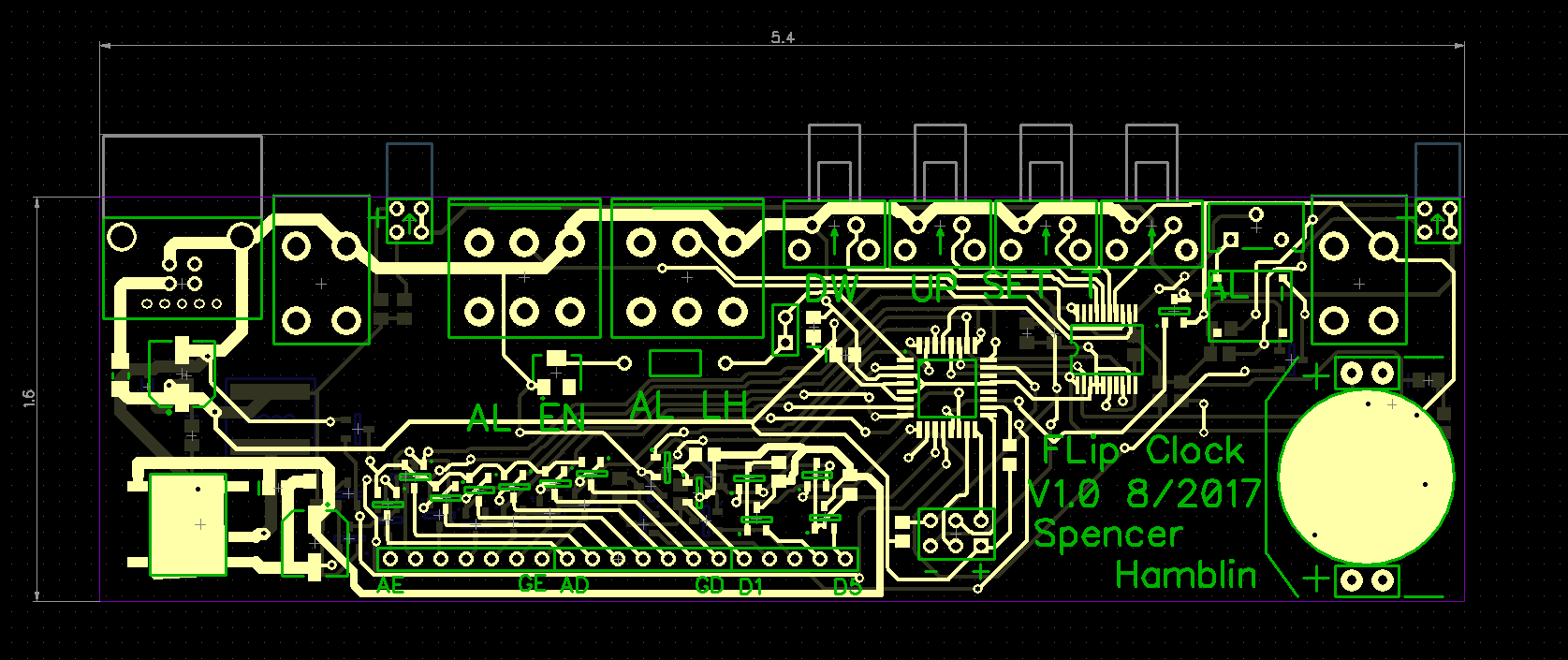
On the lower left you have the 12v module to generate the power to drive the displays. On the lower right you have the coin cell and the RTC. The RTC is under the coin cell. With such a large ground plane it's the perfect location. In the lower middle you have the driver circuitry happily taking up both sides of the board.
The buttons take up the top portion. I could have used SMD buttons but I trust though hole more for that. The end total is 8.6 square inches and 321 connections.
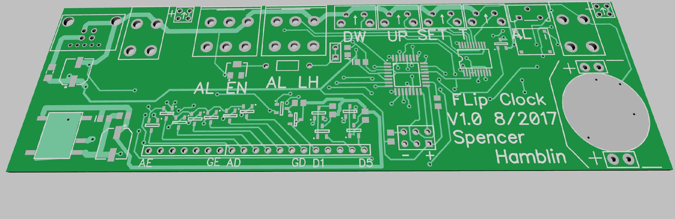
Here's the board in glorious 3D
I think I'll use OSH parks fast service. It's pricey but i REALLY want this done before school starts. I think this is one of my largest PCB's to date. Let's hope I don't need a version 1.1.
Discussions
Become a Hackaday.io Member
Create an account to leave a comment. Already have an account? Log In.