 Spencer
Well I have good news and bad news in this update. The good news is the PCB is in and tested. The bad news is I had to make adjustments and send off version 1.1. Bellow is a very telling picture.
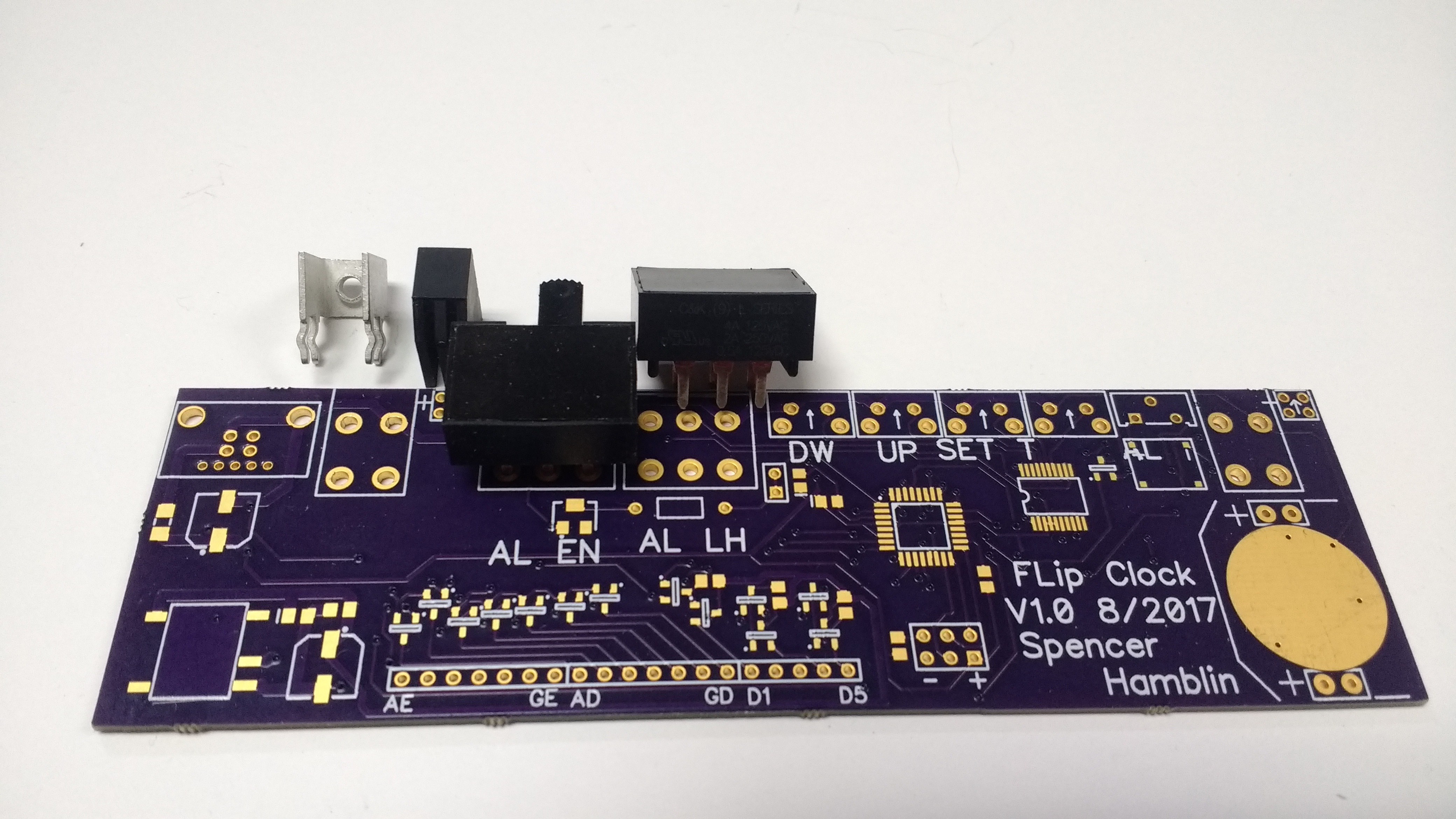
All 4 of those parts should line up with the pads. They do but the large black switches get in the way of nearby parts. This shifts the whole row. The large screw terminal to the right also has the pattern rotated 90 degrees by mistake. I have tight space constrains in the clock so no possibility of a bodge or hack to make it work.
Since I had a PCB I decided to test what I could. I soldered on the buzzer, 12V power converter and part of the display drivers. The ATMega 48A was put on as well.
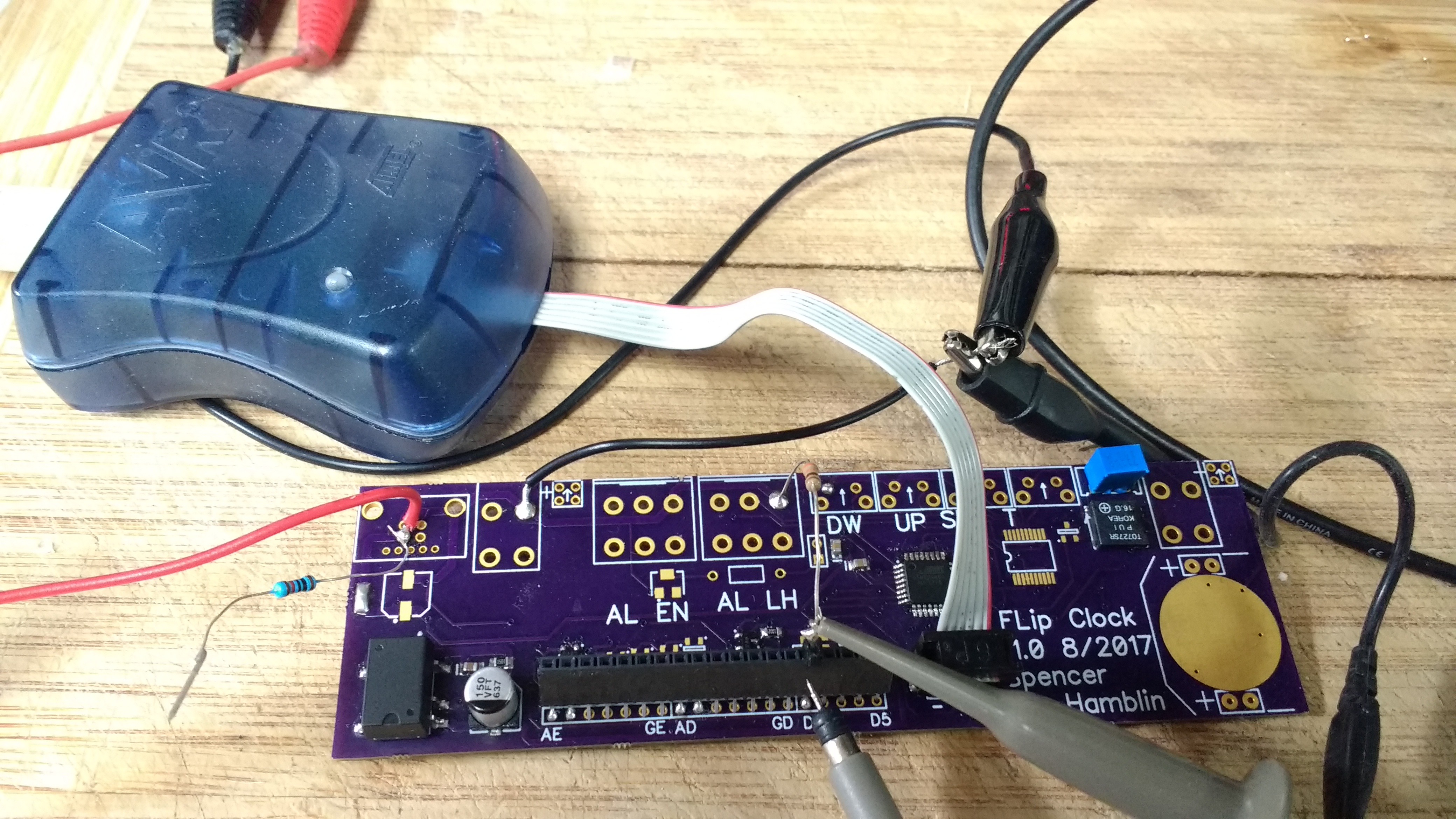
On testing the 12V supply worked fine. It floated at around 13.3V, a little high with load but for my uses it's good enough. Buzzer had no issues thankfully. However my driver circuit had a minor error in it. Swapped a pad around in CAD and now the PNP MOSFETS will do what there supposed to.
I added a few minor things I forgot as well. Just a few debug test points. SDA, SCL and the like.
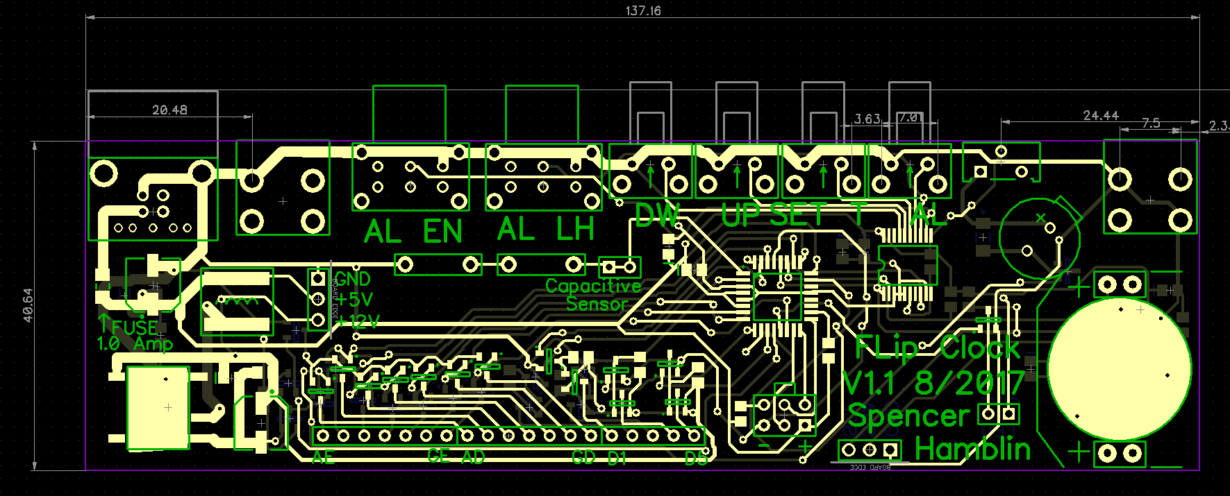
In case your curious here's version 1.1. You can see the new test points and different switches to get around the size issue.
There's two lessons to be learned here. Test fit the big parts first on a print out of the PCB. Additionally don't expect to get it right on the first try. Nothing wrong with needing a second version for most projects if you have too.
That about wraps up this update. I've posted the new PCB Cad files and a PDF schematic.
Discussions
Become a Hackaday.io Member
Create an account to leave a comment. Already have an account? Log In.