 Ruud van Falier
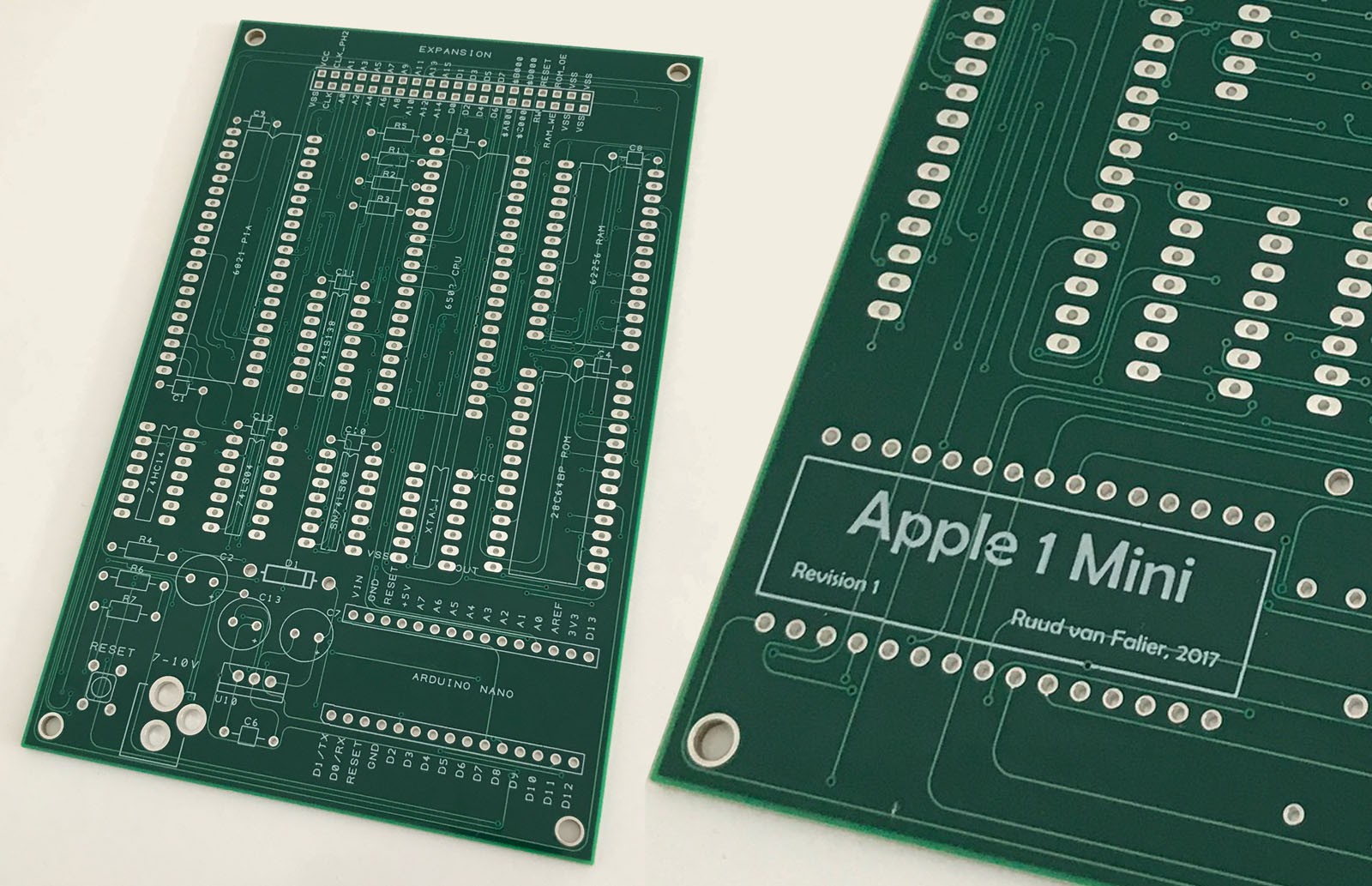
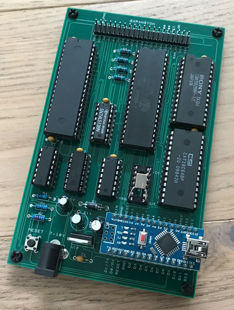
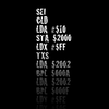
This project is a minified replica of the Apple 1. It's built around a 6502 CPU, 6821 PIA (Peripheral Interface Adapter), RAM and ROM - just like the original Apple 1, but it uses an Arduino Nano to enable serial communication between the Apple 1 board and an external computer that acts as terminal. That means you can't hook up a keyboard and monitor directly to the board (yet!).
The project is heavily inspired by the Briel Computers Apple 1 Replica and The Ben Heck Show!
What I have done:
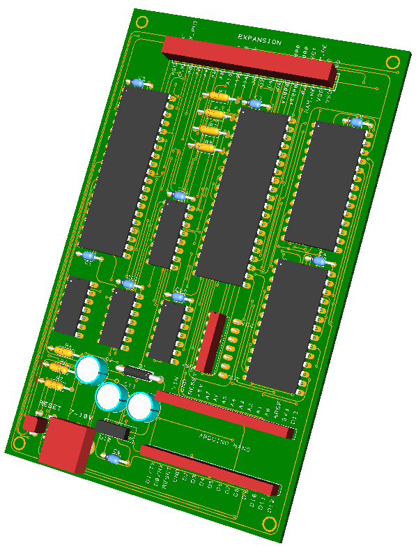
- Redesigned the circuit so I would fully understand every aspect of it.
- Designed a PCB that can be easily produced and included in a modular DIY kit for anyone that wants to build this at home.
- Programmed the ROM so it only contains BASIC, Krusader (assembler) and the Woz Monitor (memory monitor).
- Written firmware for the Arduino to enable serial communication in a way that gives the real Apple 1 feeling.
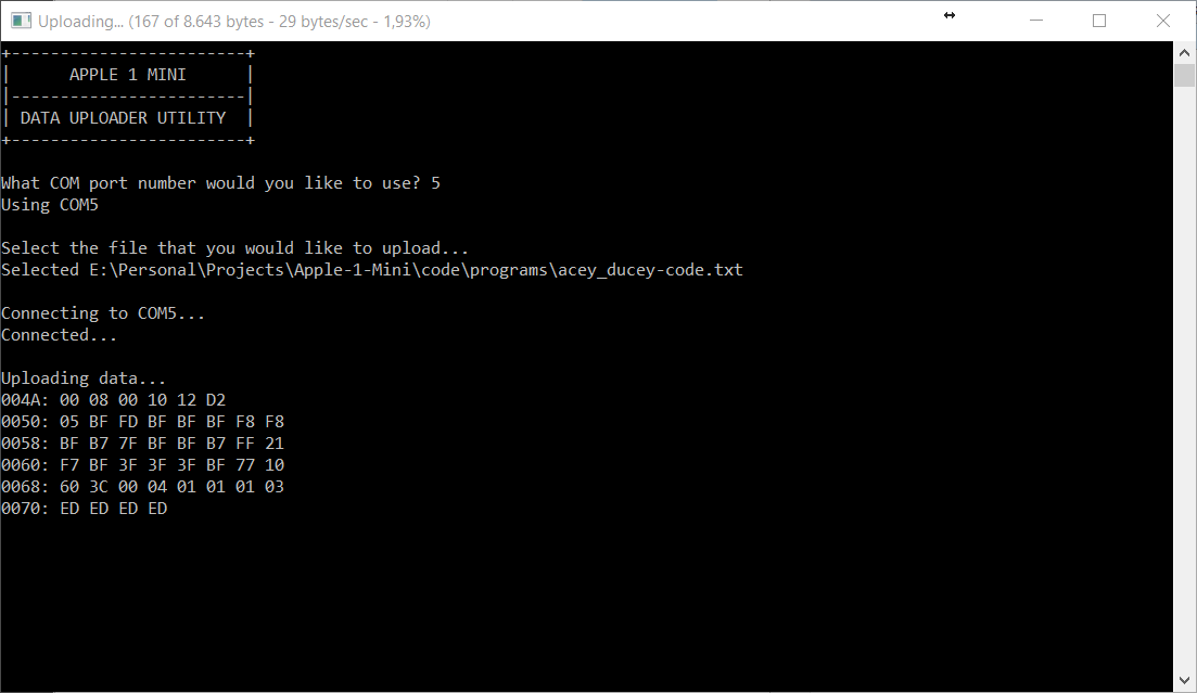
- Written a simple utility to upload data to the computer. This proved to be difficult with existing tools as there need to be specific delays in sending the data.
What I have planned:
- Design an expansion board that allows you to connect a keyboard an monitor directly to the board and run the Apple 1 standalone. The main PCB has an expansion header that allows an expansion board to be put on top of it (like a breakout board).
- Design a modular casing with laser cut parts. The casing will house the main board, but additional layers can be put on top of it to increase its size and allow for expansion boards to be added later on.
- Release several varations of a DIY kit for this project (PCB only, PCB + passives, PCB + passives + casing, complete kit, etc.) so others can easily build the computer at home.


 DIY GUY Chris
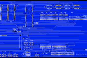
 Josh Kittle
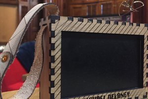
 Michael Delaney
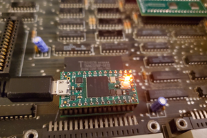
 Ted Fried
It's a pleasure to still find some people interested in Single Board Computers using old style DIP ICs! I think this will be even better if you replace that Arduino Nano with a DIP Microcontroller.