-
1Cutting the Chassis
While Boxes.py allows setting any thickness this is really meant be be cut in 3mm plywood with the exception of servo mounts in the body (the two top most parts) which should be cut from 5mm plywood to get the right depth for the servos. Material with different but similar thickness should also work just fine. Check that the (body) servos will poke through the two layers. Always measure the actual thickness as it often differs from the nominal value. Baltic birch has worked well for us. Poppler is a bit weak but may work now as some weak points in the model have been addressed.
For the head you do not need to change any settings except the burn value. It depends on the properties of the laser cutter and material you are using. It is possible to cut the parts stiff enough that most joints do not need to be glued together. But then you may need a hammer, vice or press to get things together. If you use brittle material as acrylic this is not an option and you have to use a smaller burn value to get a more loose fit.
For the legs you have a few settings to consider. The anklebolt diameters are meant for a M3 screw that get threaded directly into the wood. If you are using a different screw size you need to adjust these two.
The default leg length is 37mm. But we found the robot to be a bit less prone to falling over with shorter legs. 34mm being the minimum - which is what we used in our workshop.
Note that you may want to add some logo at the side of the head before cutting the head. Just edit the resulting file in your vector graphics / CAD program e.g. Inkscape.
Depending on your laser cutting software it may be necessary to manually select the order of the parts cut. For the head the rectangular holes in the hinges need to be cut first. Then all the other holes and the outer border of the parts last.
-
2Assemble The Head
Check if you have all parts
![]()
Start with the top part.The hole for the USB port must be on the left of the robot (on the right when you are looking at it from the front)
When assembling the bottom part put the top part in place before adding the side pieces.Glue in the servo mounts and screw in the first two servos.
-
3Solder the electronics
![]()
Solder the pin headers to the Arduino Nano.
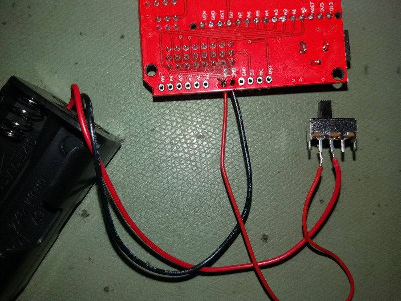
Solder the sliding switch between the battery holder and the break out board using the red wire. Also solder the black ground wire of the battery holder to the breakout board.![]()
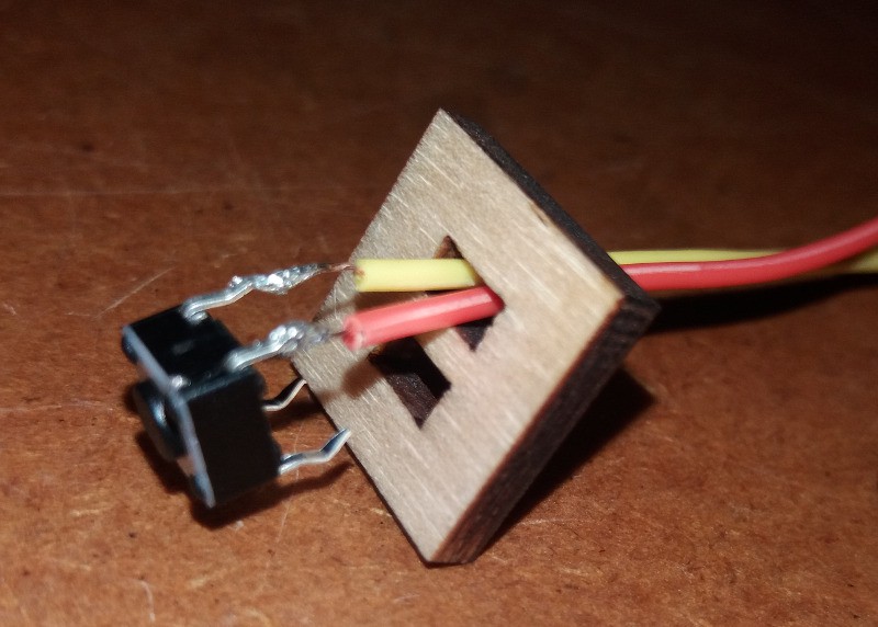
Cut off the headers of two jumper wires leaving female connectors at the other ends. Put them through the push switch mounting plate and solder them to the push switch on the other side:
![]()
Then press the pins of the switch into the holes of the plate.
-
4Assemble the Legs
At first glue the support plate to the top part:
![]()
The two legs must be symmetrical. It is easiest to build the two legs side by side, putting the same side plate down but have the servos point in opposite directions (e.g. both out).
(This still needs images)
There are two small walls that go to the inside and hold the servo in place. The smaller one goes into the back wall (the one with the notch for the servo). The other one is held between the side plates (the biggest parts). The back plate is mounted with the servo notch to the bottom. The front part is on the opposite side with the hole also at the bottom.
Place the servo in the legs before closing them completely. The servo cable goes up behind (along the bottom side of the servo) and exits the leg through the rounded holes.
-
5Install the electronics
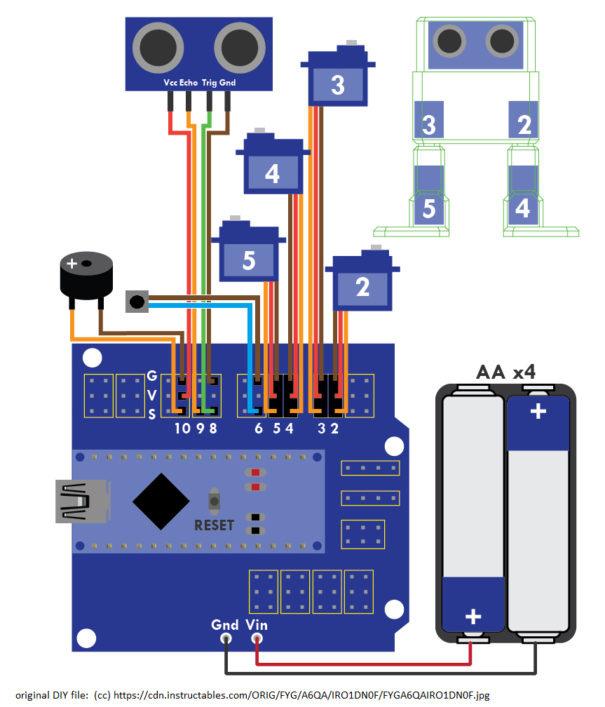
Connect the remaining pieces with the jumper wires according to this plan. Note that the legs have the servos pointing to the back of the robot and the holes for the servo cables should point to the middle. The cables of the leg servos go through the hole in the bottom of the body before they get plugged into the breakout board.
![]()
You need to install in the ultra sonic "eyes" first. If the connectors of the ultrasonic sensor are angled you may need to bend them back so that the jumper wires are horizontally when the head is closed and does not collide with the battery holder later on.Then carefully slide the break out board in place by lowering the side with the power cables under the ultrasonic sensor board. When laying flat on the floor/ceiling it should be held in place by the spring in the right back corner.
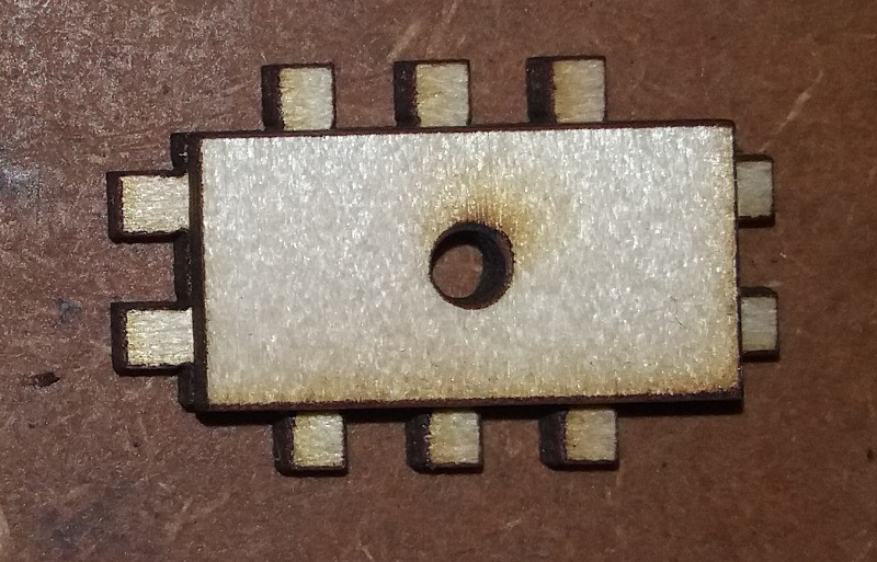
Put the main switch and the beeper in their places at the bottom back. Glue them in place if necessary. Glue the small piece with the push button on the inside of the side wall with the switch sticking through the hole. The slits in the piece need to be horizontal for the switch to fit.
At last put four AA batteries in the holder and place it between the to body servos. You may need to organize the (servo) cables a bit the make enough room.
-
6Attach legs and feet
Before installing legs and feet turn the robot on and run a program that will make it stand straight to have the servos move in the middle position. Try not to turn the servos during assembling. If necessary rerun the program.
To make assembly easier chamfer the hole on top of the top plate of the legs. The press them on the servos with the long sides being parallel to the sides of the robot. Pull them fully on to the servo using the screws that come with the servo.
You can now gently put the legs on to plates. The servo must point to the back of the robot and the holes for the servo cables should point to the middle.
Put the back ankle plates (the ones with the big hole) onto the feet. Put the one sided servo horns through the hole from behind pointing to the "toes". Then put the feet on to the servos of the legs. Make sure the feet are flat on the ground (aka orthogonal to the legs). Turn the robot on to double check. Then glue the c shaped pieces on the ankle to keep the servo horn from rotating.
Put the front ankle plate on the feet and screw in the M3x6mm screws in the front. Make sure the holes of the ankle and the legs line up.
When turning the robot on again it should stand up pretty much straight. Small misalignments can typically be adjust in software (depending of the firmware you are using). For larger errors you should disassemble the part and put it back together.
If you care confident that everything is OK you can also glue the legs on - although that might not be necessary if the robot is build with a stiff fit.
Your Otto LC is complete now. You may want to replace the program with something more fancy or even create your own moves.
 Florian Festi


Discussions
Become a Hackaday.io Member
Create an account to leave a comment. Already have an account? Log In.
I did not understand the thickness of the wood. most of it is 3mm, but which part exactly is 5mm?
Are you sure? yes | no
The only pieces that are 5mm thick are the ones the servos in the body gets mounted on. They can be seen in the first picture of part 2 in the top left corner labeled "Servo Halter" which is German for servo mounting plates (literally "servo holders"). They need this thickness so the servos are flush with the bottom of the body.
Are you sure? yes | no
To switch between different programs.
Are you sure? yes | no
what is the push button for?
Are you sure? yes | no