0%
0%
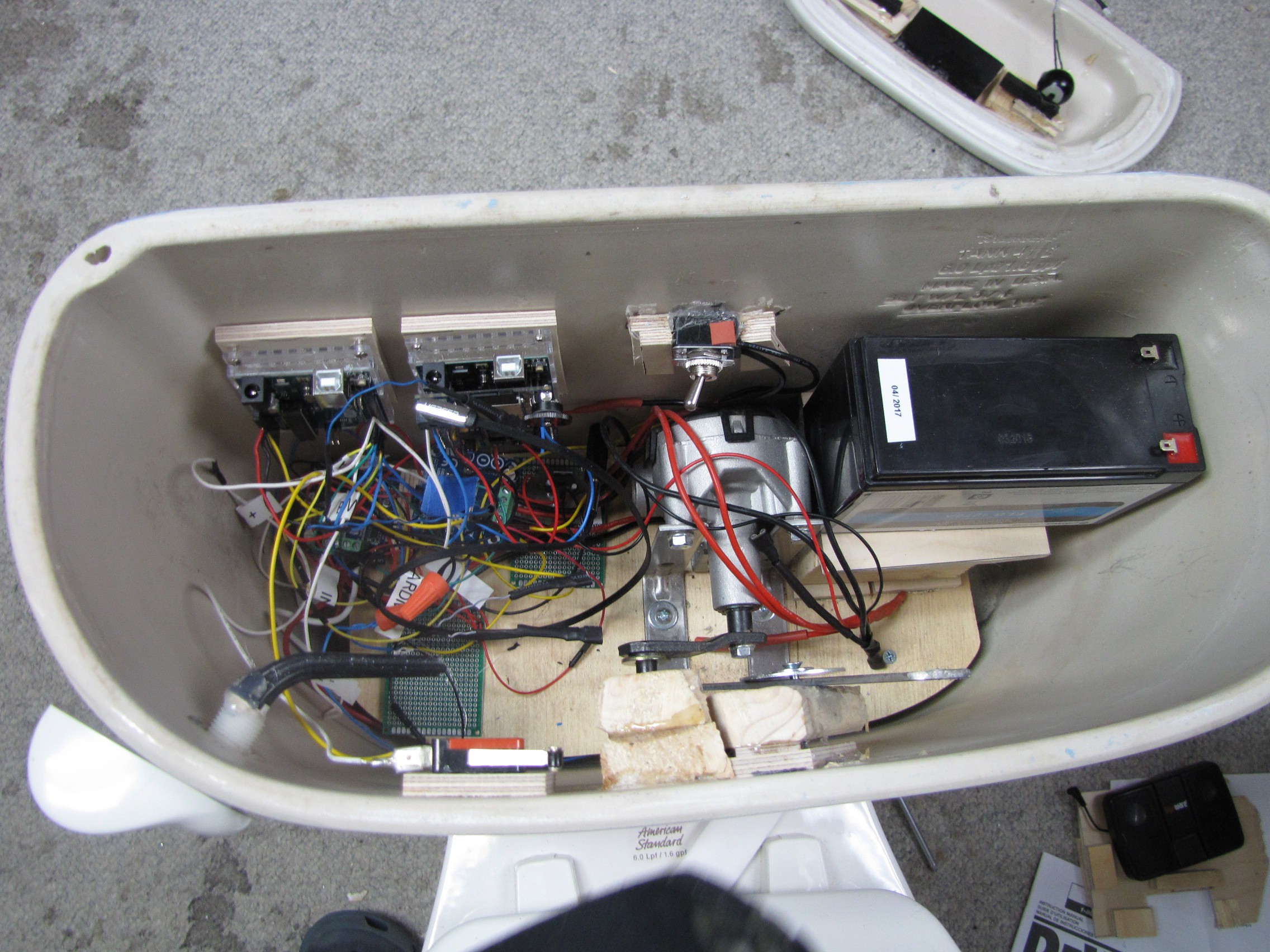
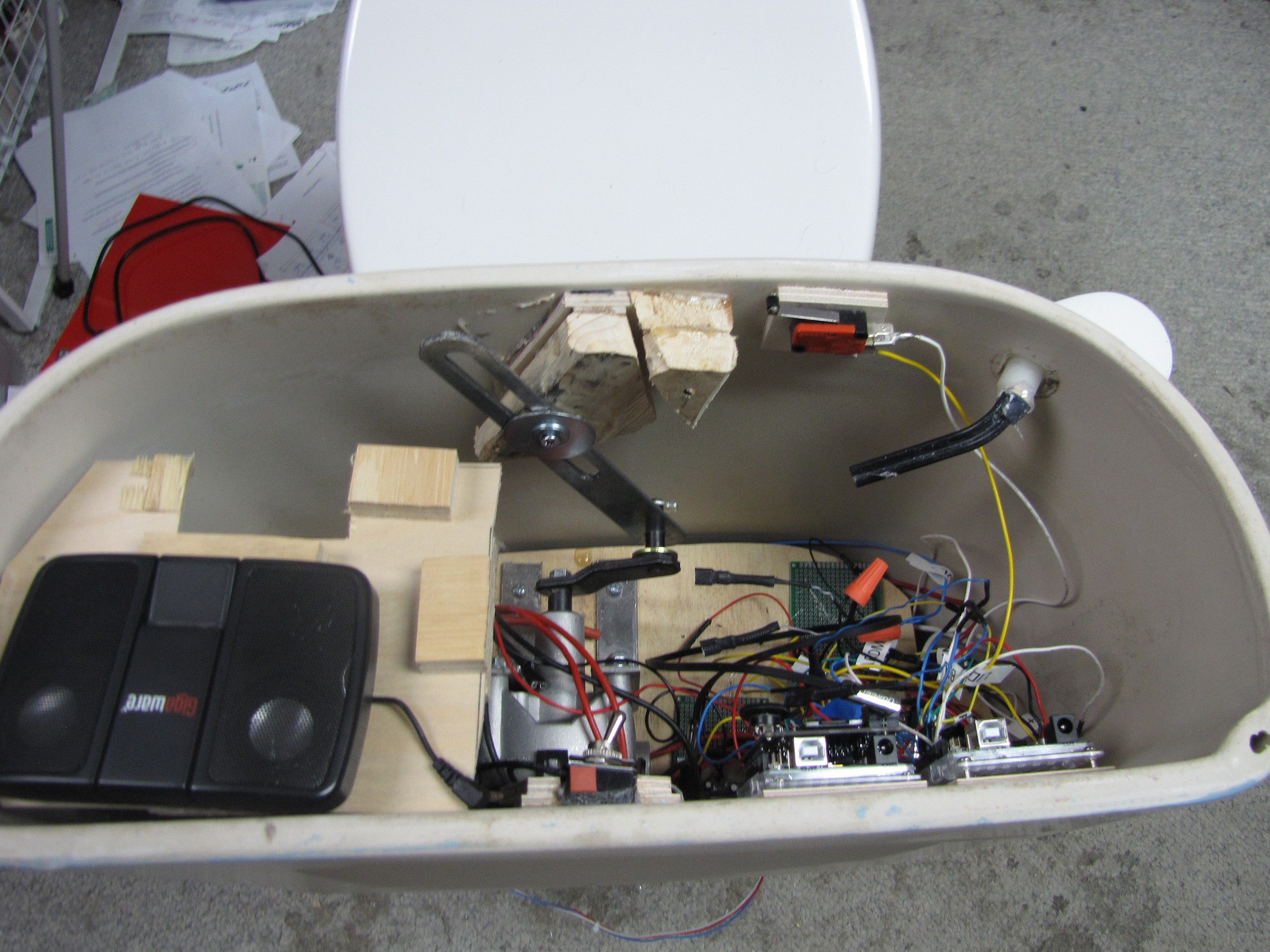
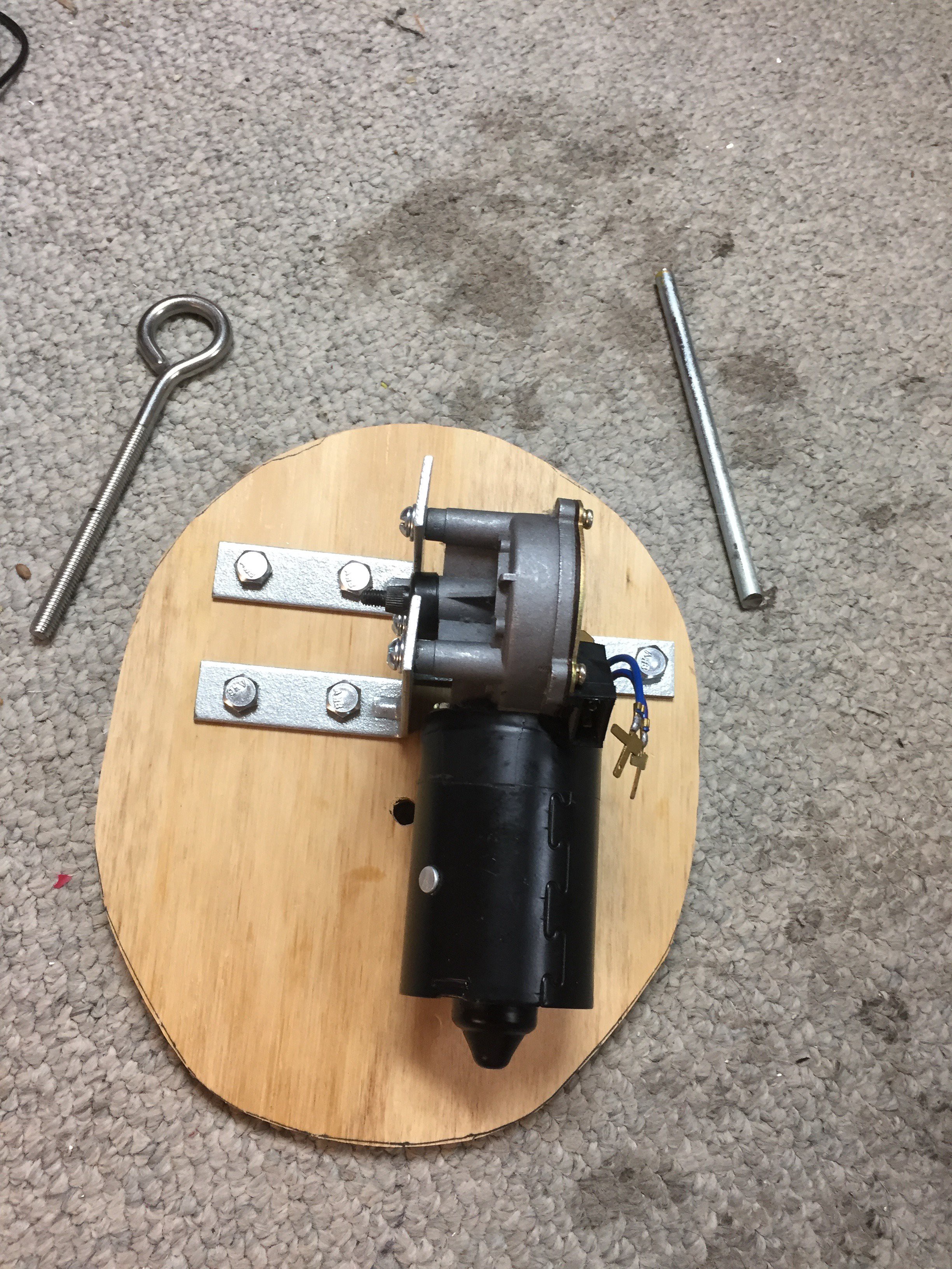
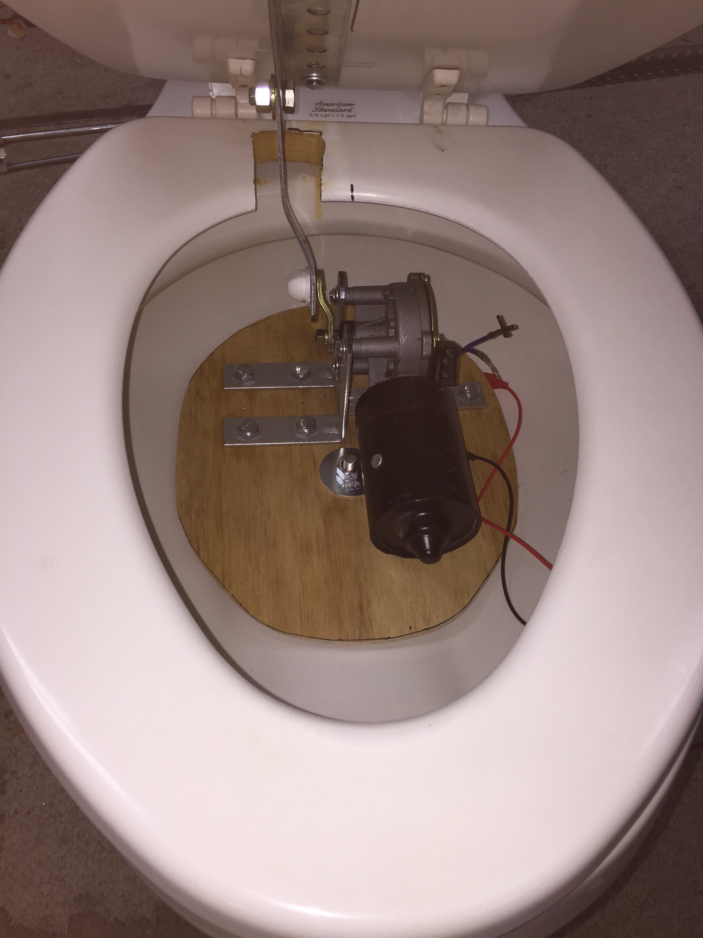
Captain Underpants Toilet
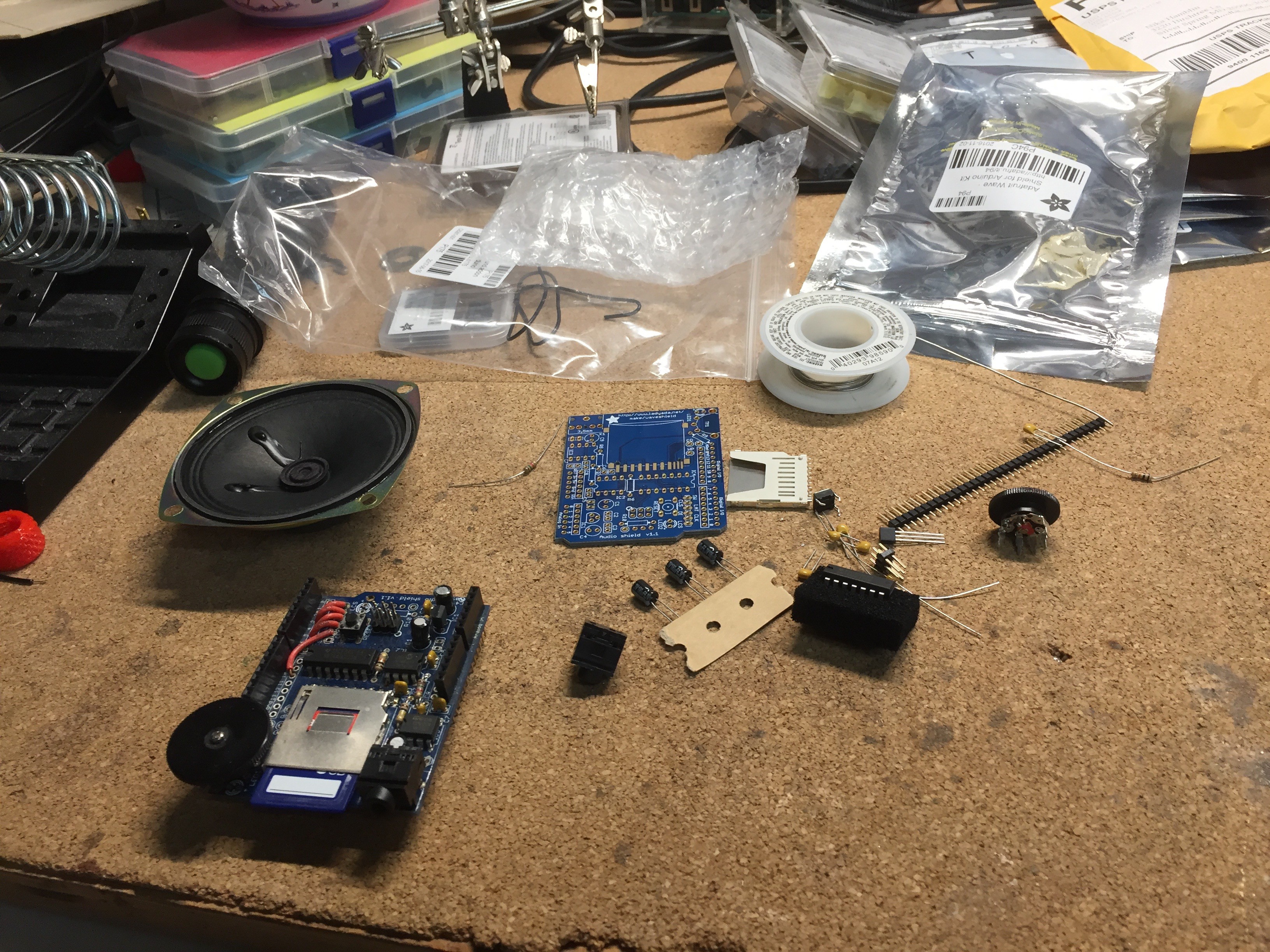
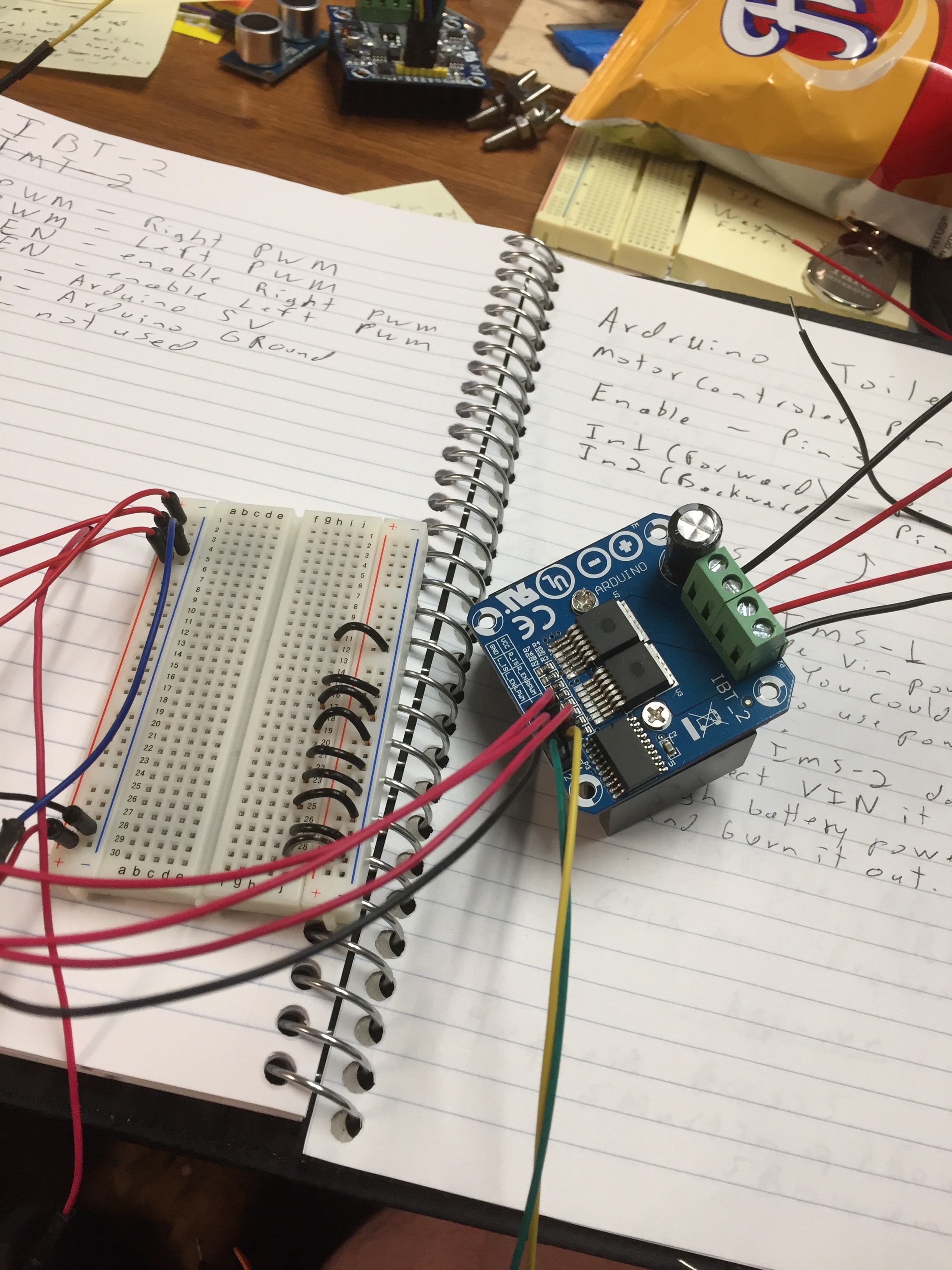
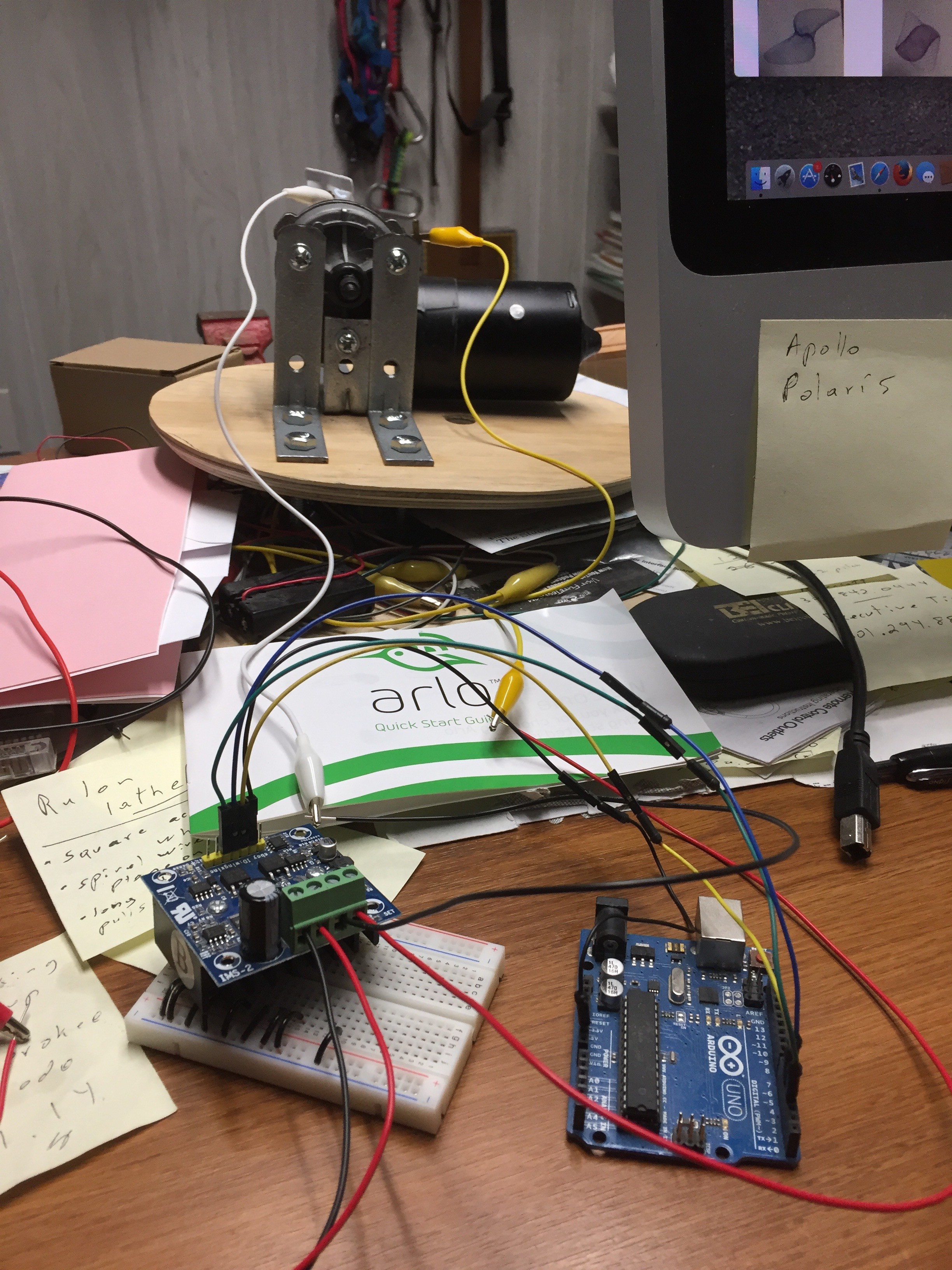
Arduino controlled Toilet using wiper motors and wave shield, range finder. Eyes made out of ping pong balls with green LEDs
Become a Hackaday.io member
Already have an account? Log in.
Just one more thing
To make the experience fit your profile, pick a username and tell us what interests you.
Pick an awesome username
hackaday.io/
Your profile's URL: hackaday.io/username. Max 25 alphanumeric characters.
Pick a few interests
Projects that share your interests
People that share your interests

 Ossum
Ossum
 Eric
Eric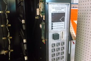
 Matthew Potter
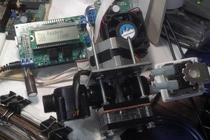
 James Newton
Maximum performance (MaP) testing conducted by independent agencies determines how much solid waste a toilet can handle. check here for more detail about these best flushing toilets.