 xres0nance
The Inception
The theme for DEF CON 25 this year was retro-tech, and for several months I've had the idea to make some kind of retro badge. I wanted to do it just for fun, and as a conversation starter, at which it was a great success!
This badge was made almost entirely from actual retro parts from the late 80s and early 90s, right down to the Radio Shack perfboard, wire, and roll of solder I used. Only the resistors and the 555 were newer, because I didn't dig long enough to find the old ones!
Retro enough for ya?
In a masterful stroke of planning ahead and leaving plenty of time to spare, in the last few days leading up to def con I kept telling myself, "gee, I should really start on that badge..." To be honest, I didn't even know what I wanted the thing to be, other than some vague notion of using no microcontrollers, and building it by hand on oldschool perfboard, if I had any left in the junk bins.
The evening before I had to fly out at 0800, I figured it'd be a great idea to go out drinking with friends; after all, I only needed to sit on a plane to Vegas for six hours =) This was not a great idea. I was mostly packed beforehand, but I had not yet figured out what to bring to do the badge. When I got back that night, I drunkenly grabbed parts that seemed right, chucked em in a box, and got three hours of "sleep."
The Design
I got to the airport with a three-alarm hangover, but determined to make this badge happen. Knowing that I had no time to spare, I started designing the thing while on the plane. I'd alternate between sketching circuits, reading the few datasheets I could get over the spotty in-flight wifi, and taking micro-naps to sleep off the beer.
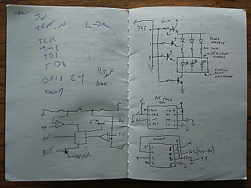
The components were in a checked bag, and I didn't really remember what parts I actually brought, or how many. There was a lot of best-guess engineering, here =) These are the few pages from my notes. (Ignore the jtaggy scribbles; that's from previous stuff.) First I sketched out the row and column drive setup for the diode-matrix and display. Wasn't really sure if it was a common-anode or common-cathode display, but given the age, common-cathode was the good bet, so I went with it and got lucky. Also figured some 555 circuits and ballpark component values for clocking the thing, and a power-on reset that I didn't end up using. You can see the innards of a 555 sketched out too. (I'm sure I had some good reason for doing that...)
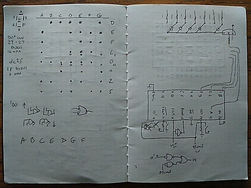
Next I figured out the diode matrix encoding for the display. I had no idea how many diodes I brought, or driver transistors, other than "a bunch". Hedging bets, I worked out the less-diodes-required DC25 text, and longer DEF CON text. The latter I also did an emergency diode-shortage version using a smaller "o" and "c" which would have saved me three diodes!
Here I also dug into the '595 datasheet, and started loosely laying things out physically to get a sense of how to orient parts on the board. I also realized I'd need some kind of reset, and a way to inject bits, so the 74F00 came into play to glue some signals together. I probably could have done this dirty with carefully-chosen resistors and such, but was far too tired to work that out on paper between TTL and CMOS chips!
The Construction
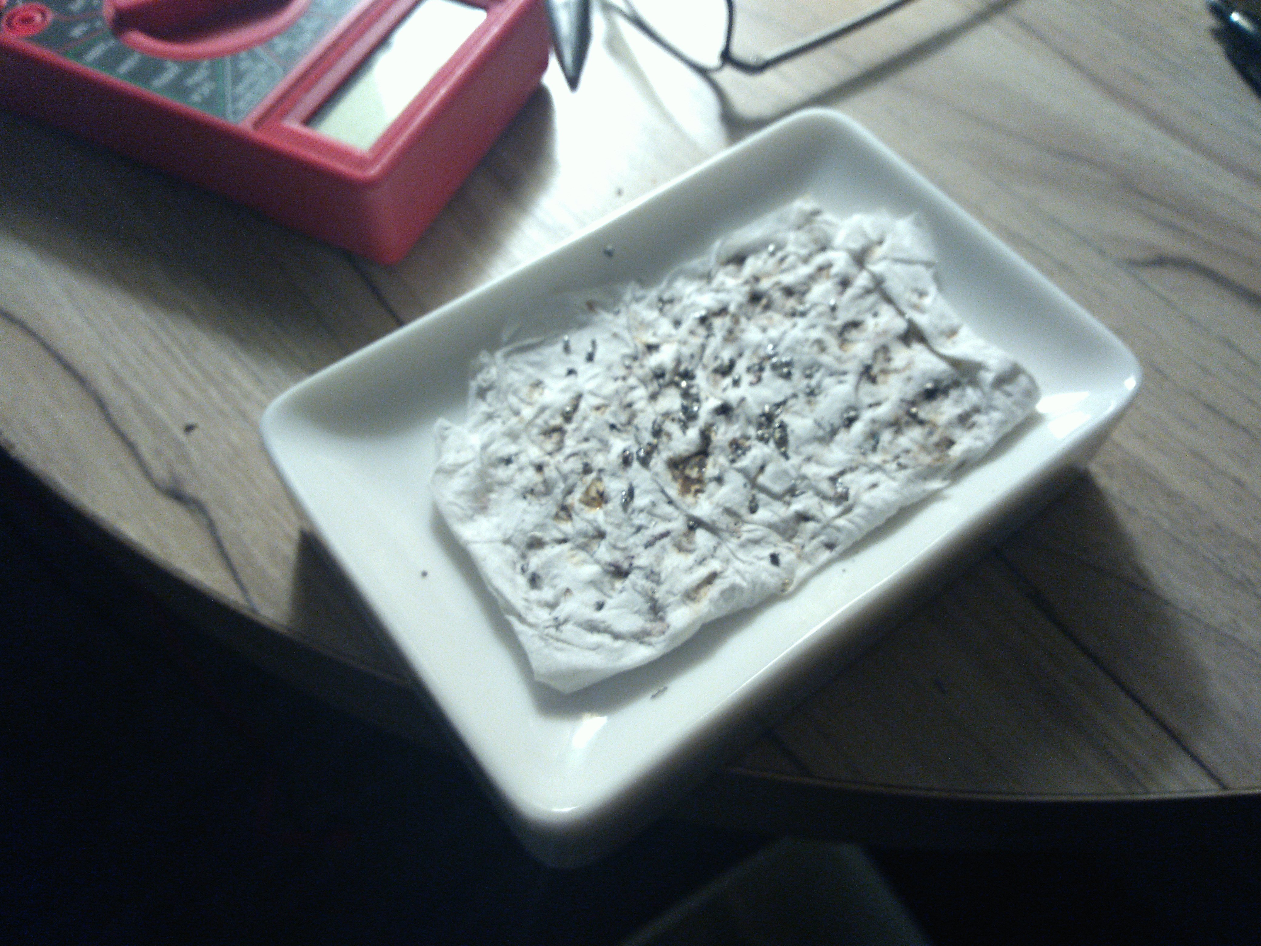
Arriving at the hotel around 1400, I had a choice — get some much-needed sleep, or build the badge. I knew there was no way I'd want to do it the next day, as the con would be kicking up. It was now or never! I had brought with me a USB soldering iron which I found for $6 direct from China. This thing works far better than it has any right to! I suspect the tip is not iron-clad, or if it was the cladding disappeared quickly, as the tip would get dirty quickly. Riding the power to keep temps down helped a bit. I rigged up a soap-dish cleaner that worked well enough:
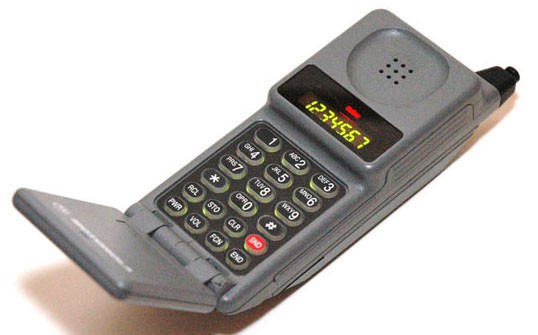
First I reverse-engineered the pinout of the display module. This was pulled from an old Motorola MicroTAC DPC analog cellular phone, and has seven 7-segment digits in green, and four lights along top in green, red, and amber. This is the old phosphide green, not that newfangled nitride stuff ;) You can see the display working in a similar phone here:
and the final pinout:

I would have kept that phone intact, since they can be turned into a scanner for the analog cellular bands used back in the day, but there are far easier ways to do such things now and I need to clear a lot of space.
(You'll forgive me, dear reader, as I was not quite lucid enough to take progress photos the entire way along. Although I did notice that exhaustion worked well somehow to keep me focused entirely on this build.)
First I wired the diode matrix. This is effectively a hardwired ROM containing the data to display on the 7-segment module, and works very much like a diode-switched keyboard matrix. Even with the tiny number of diodes I had to wire, I now have new-found respect for those who once wove ferrite-core ROMs and such!
Next, I tied that together with some row and column NPN drivers, hooking it up to the display. Here I ran into two problems: First, I put the display in upside-down, and wondered why nothing worked. Oops =) It was not easy to fix, as I brought no de-soldering stuff! Second problem, I found that while I had enough diodes, I was one transistor short! My display would only read "DEF CO", which was just no good! Figured I'd leave that problem for later.
Then I wired up the logic chips and 555. I did this using 22 gauge wire, the same way I did a very long time ago. That 22 gauge seems mighty big when things start to get densely packed, but I resisted the temptation to reach for the 30 gauge. I would also use cut-off component leads, insulation bits for sleeving resistors, and formed the ghetto-switches from a bit of wire hanging just over another bit. Here's the resulting mess on the back:
Amazingly, it mostly worked the first time! I had to tweak the pull-up resistors on the '00 chip, as 10k is not punchy enough for TTL. And I finally had to get that last digit working for the N in DEF CON! Lacking any more 2N2222 transistors, I found a CD4066. This is a CMOS analog switch — control pin goes high, and two other pins are now connected. Close enough! Wired it in, and it worked. But, the "N" was too dim.
It turns out running this at 5ish volts makes the on-state resistance a bit high, around 100 ohms. So, I doubled up two in parallel, and that made it bright enough. (I figured being a CMOS part this would not blow up; bipolar doesn't parallel up quite as easily without ballast.) In the end the whole thing worked, the desk in the hotel was a giant mess, and I was beat!
But it was worth it! (Pro tip - lockpicks make good mini-screwdrivers for trimmer pots.)
The Explanation
So here's a quick theory of operation. This is built around a shift register. (typically, designs like this would use a decade counter, but a shift register is what I had) There is a 555 timer that generates a clocking signal. The '595 has its b7 output wired into its b0 input, so that a bit shifting out the end comes back into the beginning, forming a loop. The outputs of the shift register drive the base of two NPN transistors — one is a row driver that activates a row of diodes, the other is a column driver that activates a particular digit on the display via its common-cathode pin. Base resistors were chosen to account for the extra voltage drop seen at the emitter of the row drivers, since it's feeding a pair of diodes (matrix and display). Vbe would be lower on the row drivers than the column drivers; their emitter went straight to ground.
To make this badge go, you have to kind of kickstart it. I was too tired to bother with a full power-on reset solution, so I did those ghetto buttons. As you can see in the demo video below, when it powers on, the shift register is full of garbage, and the display follows suit. You have to tap the reset button to clear the register, and then tap the bit-injector button for one clock cycle to get the single bit into the loop. After that everything works! (Note, I wired up the little square light to the clock as a debug tool during the build, and decided to keep it. Moar blinky! Also added the red light because moar!)
As a side-effect, if you inject more than one bit into the ring, more than one row of the diode matrix is activated simultaneously, and they interfere. I figured this works as a nice little glitch mode, and the other badges clanking around my neck often made this happen... heh
The Demonstration
Here's a quick demonstration of it working:
This worked perfectly as a conversation starter, and made a lot of people smile! In that, I consider it a complete success.
A number of people were fascinated that I was displaying text with no microcontroller involved, so it was great to be able to share some of the oldschool techniques that the Arduino-era crowd may not have seen yet. I also had someone very confused, wondering where the voltage regulator was! I explained that the 555 and CMOS chips have a wide operating voltage range, and the one TTL chip wants 5 volts. I had 6 volts of AA batteries, and 6 is close enough to 5 for a hacker con, so there ya go. The only "regulation" was a single dipped tantalum, that thankfully didn't explode!
Maybe next year I'll start designing a badge before I step on the airplane. =)
HACK LIKE IT'S 1989!