 xres0nance
The Inception
The theme for DEF CON 25 this year was retro-tech, and for several months I've had the idea to make some kind of retro badge. I wanted to do it just for fun, and as a conversation starter, at which it was a great success!
This badge was made almost entirely from actual retro parts from the late 80s and early 90s, right down to the Radio Shack perfboard, wire, and roll of solder I used. Only the resistors and the 555 were newer, because I didn't dig long enough to find the old ones!
Retro enough for ya?
In a masterful stroke of planning ahead and leaving plenty of time to spare, in the last few days leading up to def con I kept telling myself, "gee, I should really start on that badge..." To be honest, I didn't even know what I wanted the thing to be, other than some vague notion of using no microcontrollers, and building it by hand on oldschool perfboard, if I had any left in the junk bins.
The evening before I had to fly out at 0800, I figured it'd be a great idea to go out drinking with friends; after all, I only needed to sit on a plane to Vegas for six hours =) This was not a great idea. I was mostly packed beforehand, but I had not yet figured out what to bring to do the badge. When I got back that night, I drunkenly grabbed parts that seemed right, chucked em in a box, and got three hours of "sleep."
The Design
I got to the airport with a three-alarm hangover, but determined to make this badge happen. Knowing that I had no time to spare, I started designing the thing while on the plane. I'd alternate between sketching circuits, reading the few datasheets I could get over the spotty in-flight wifi, and taking micro-naps to sleep off the beer.
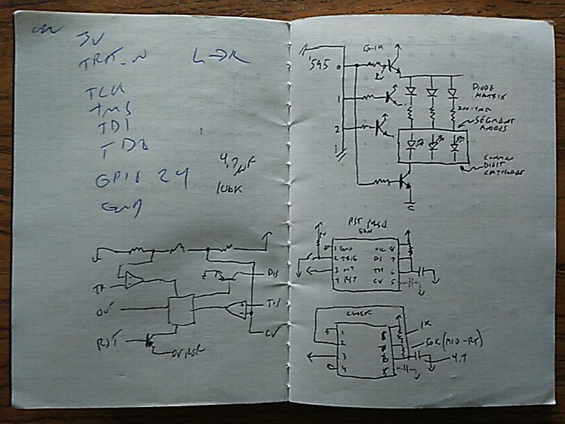
The components were in a checked bag, and I didn't really remember what parts I actually brought, or how many. There was a lot of best-guess engineering, here =) These are the few pages from my notes. (Ignore the jtaggy scribbles; that's from previous stuff.) First I sketched out the row and column drive setup for the diode-matrix and display. Wasn't really sure if it was a common-anode or common-cathode display, but given the age, common-cathode was the good bet, so I went with it and got lucky. Also figured some 555 circuits and ballpark component values for clocking the thing, and a power-on reset that I didn't end up using. You can see the innards of a 555 sketched out too. (I'm sure I had some good reason for doing that...)
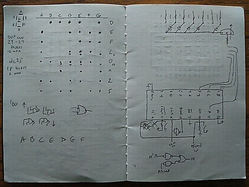
Next I figured out the diode matrix encoding for the display. I had no idea how many diodes I brought, or driver transistors, other than "a bunch". Hedging bets, I worked out the less-diodes-required DC25 text, and longer DEF CON text. The latter I also did an emergency diode-shortage version using a smaller "o" and "c" which would have saved me three diodes!
Here I also dug into the '595 datasheet, and started loosely laying things out physically to get a sense of how to orient parts on the board. I also realized I'd need some kind of reset, and a way to inject bits, so the 74F00 came into play to glue some signals together. I probably could have done this dirty with carefully-chosen resistors and such, but was far too tired to work that out on paper between TTL and CMOS chips!
The Construction
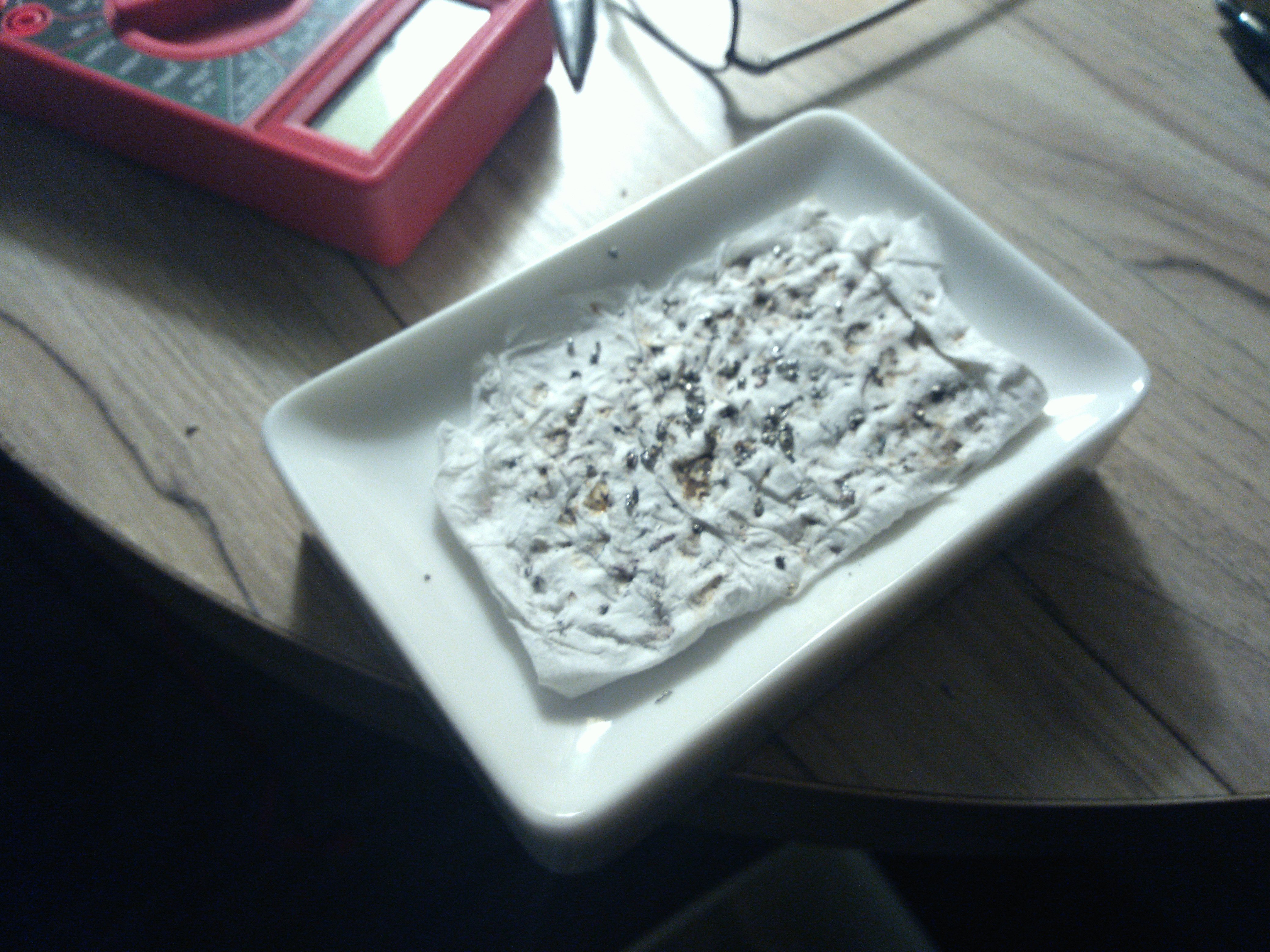
Arriving at the hotel around 1400, I had a choice — get some much-needed sleep, or build the badge. I knew there was no way I'd want to do it the next day, as the con would be kicking up. It was now or never! I had brought with me a USB soldering iron which I found for $6 direct from China. This thing works far better than it has any right to! I suspect the tip is not iron-clad, or if it was the cladding disappeared quickly, as the tip would get dirty quickly. Riding the power to keep temps down helped a bit. I rigged up a soap-dish cleaner that worked well enough:
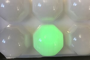
First I reverse-engineered the pinout of the display module. This was pulled from an old Motorola MicroTAC DPC analog cellular phone, and has seven 7-segment digits in green, and four lights along top in green,...
Read more »


 Morning.Star
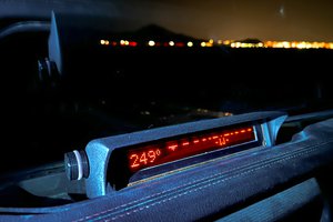
 Kevin Santo Cappuccio
 deʃhipu
Great project, thank you for the writeup! =)