Close
0%
0%

OpenRomibo

OpenRomibo Is An Open-Source Social Robot Platform Created For Language-learning, Education, And Play.

Similar projects worth following
OpenRomibo is a social robot project created by and for developers, researchers, and educators, hackers, makers. OpenRomibo is developed with language learning, early childhood education, and play in mind and costs just under $200 to build. The project requires some basic electronics DIY tools as well as 3D printed and laser cut parts. Other than Romibo's structure, all of the electronic components can be purchased around the web.

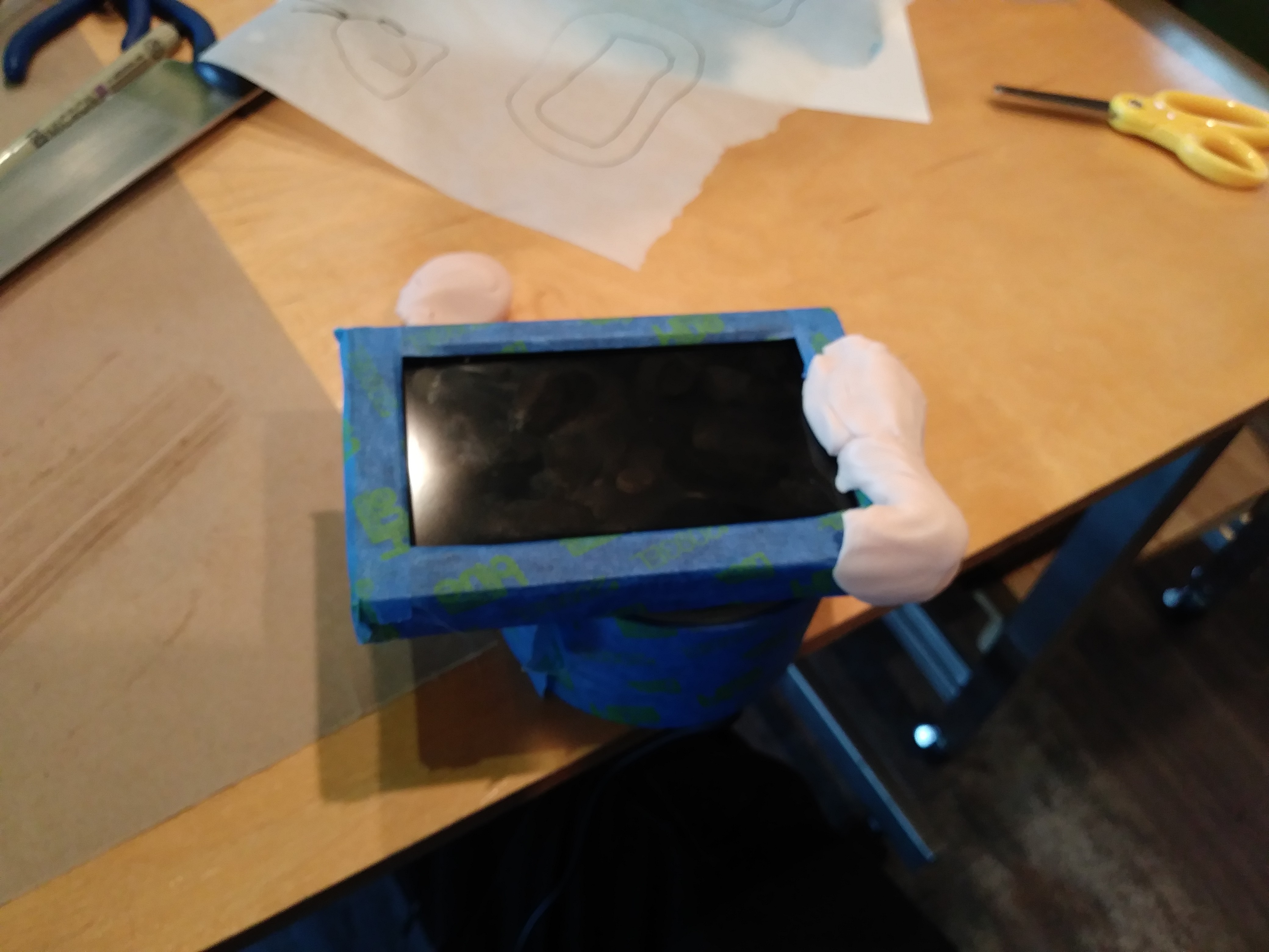
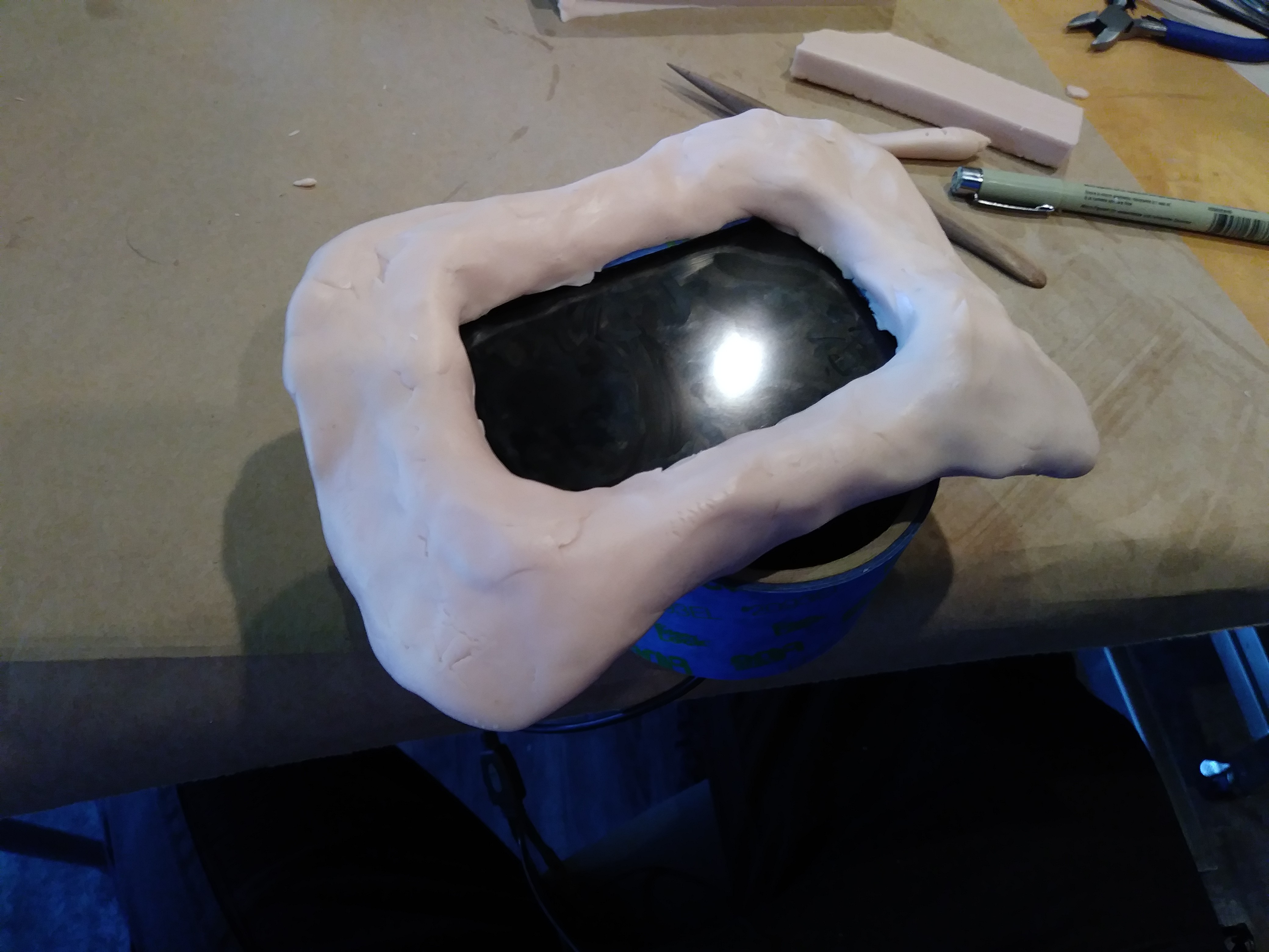
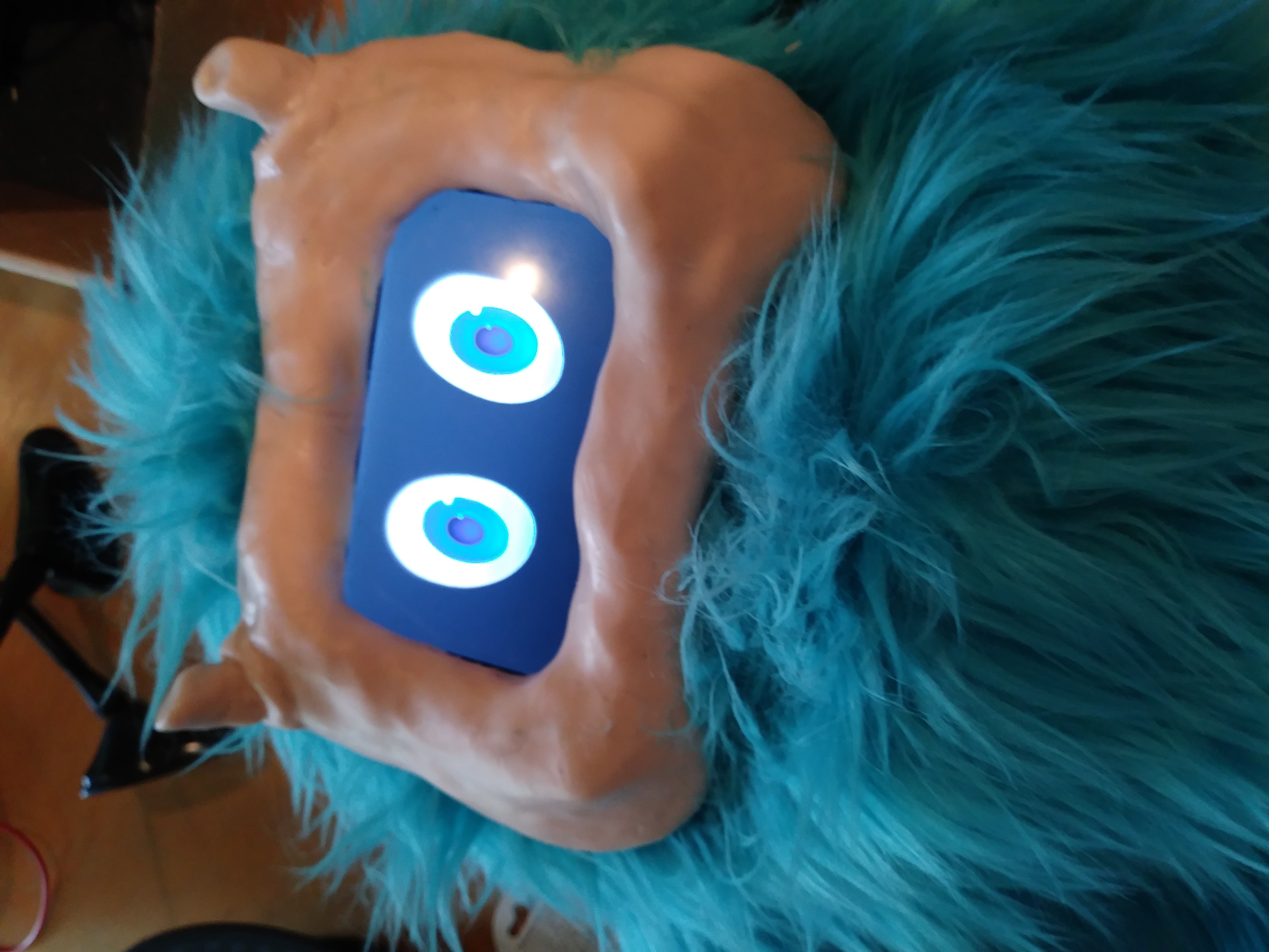
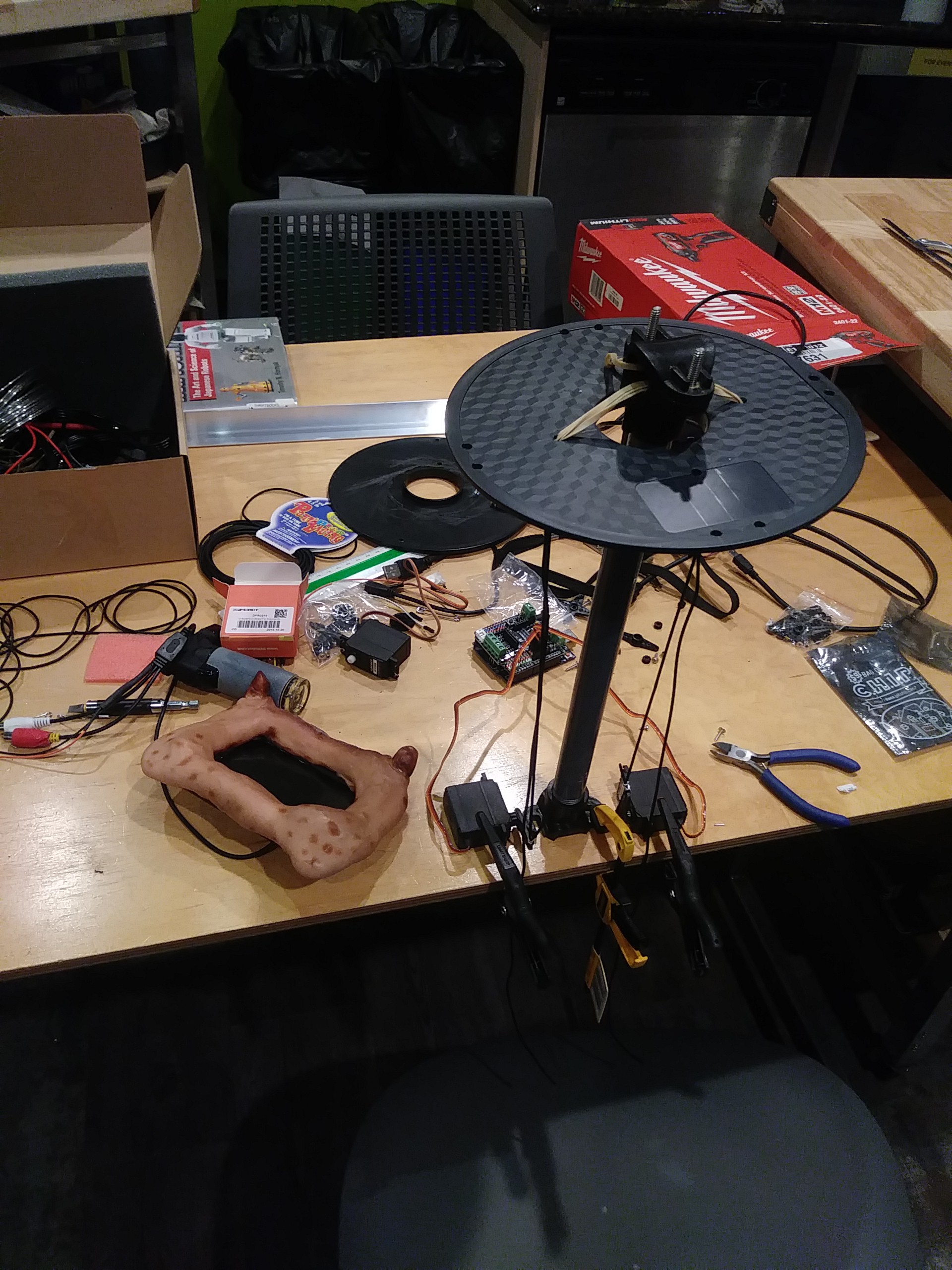
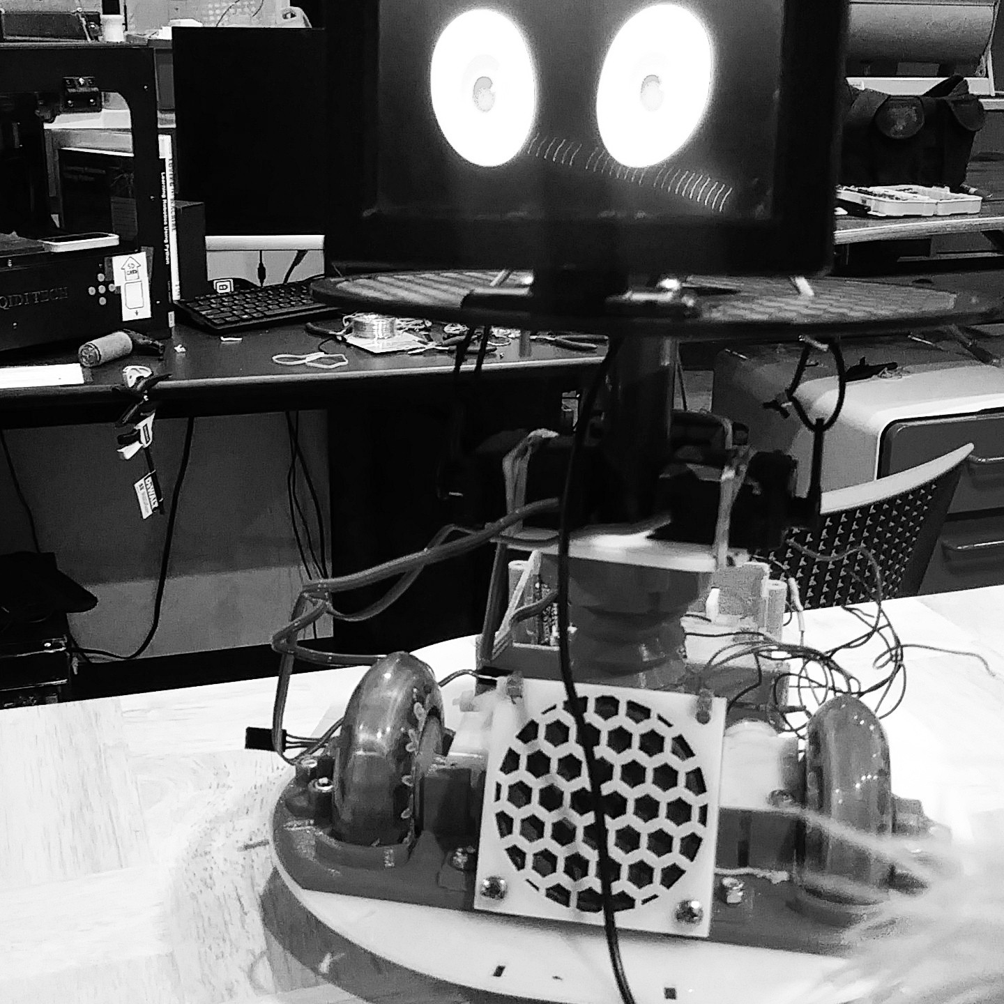
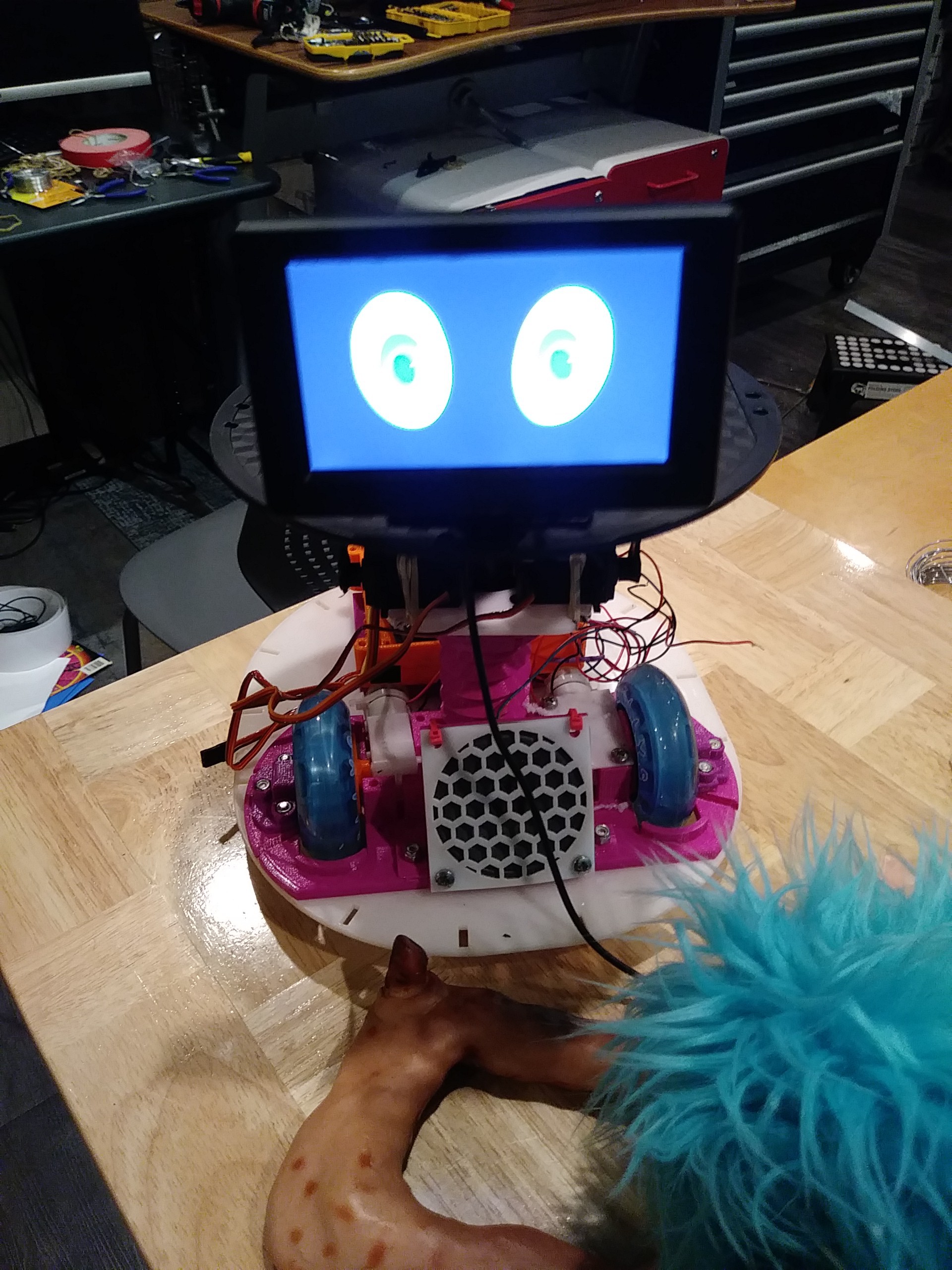
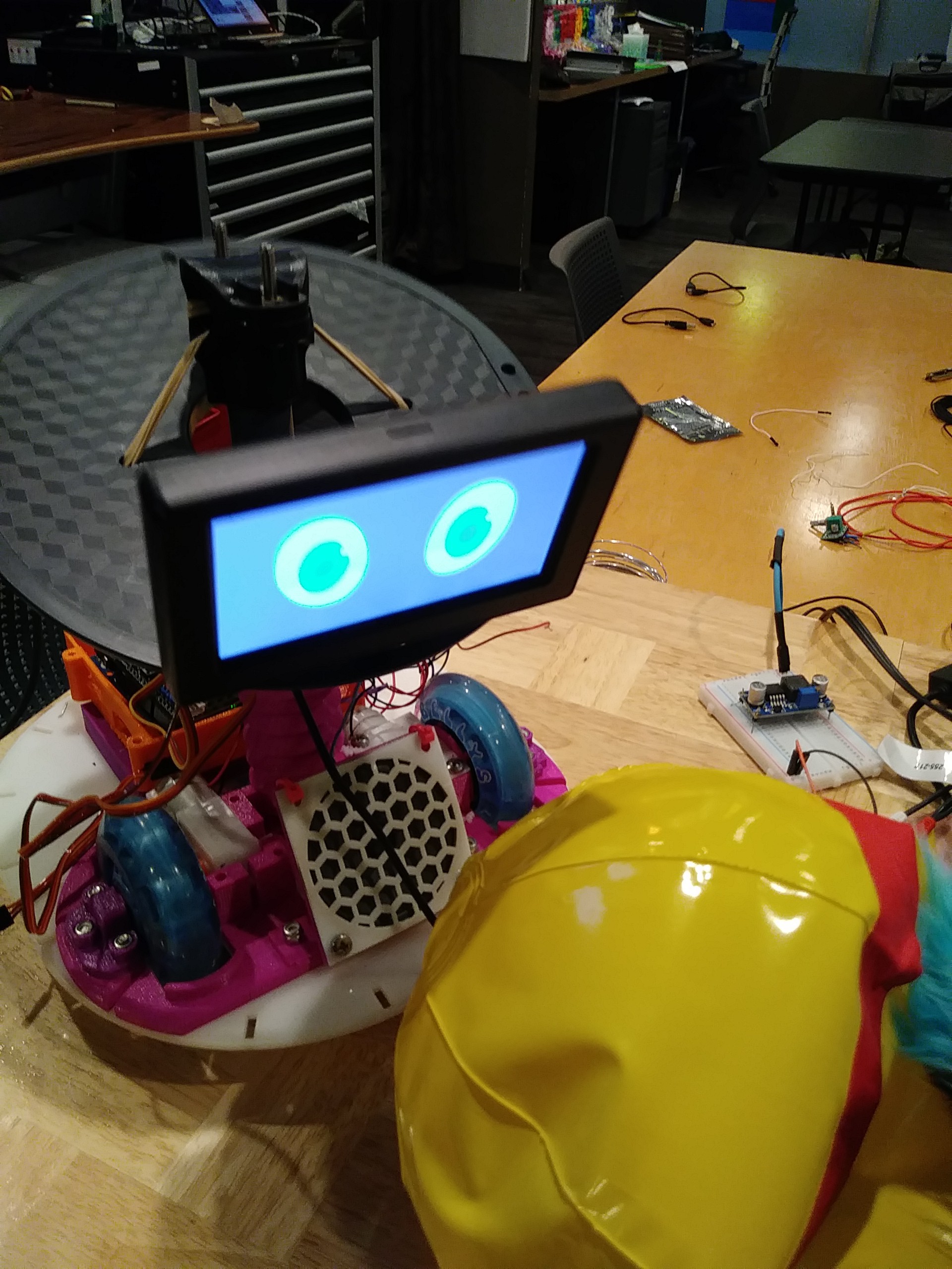
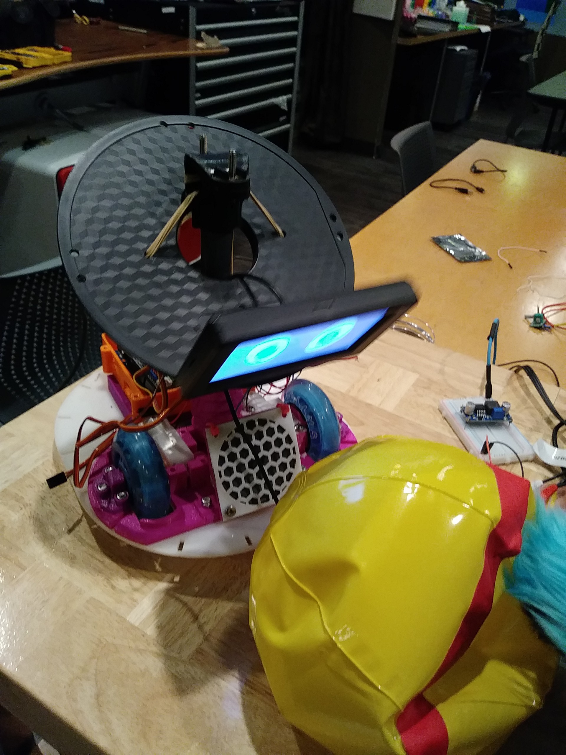
A while ago I discovered that the founders of a social robot company we're going to be shutting down but they wanted the project to live on and I thought it was an awesome opportunity to take it on. Now I'm heading up the effort to make Romibo an open source project and keep it alive and improving. I had already been on the search to find just the right robot for my own research so this seemed to be a great fit. I've come across some pretty amazing robot kits that were mostly arms, bipedal or line followers with little focus on HRI. Other platforms that covered HRI research I found to be far beyond my personal budget. Luckily, I was given access to all documentation and repositories which you can find here. Now anyone can contribute, build, modify, remix to this awesome project. 

Let's build more Romibos! 

OpenRomibo is a robot platform made by and for community. Like rasing any robot, It takes a village. Below is a list of next steps, Solving these technical puzzles would be great. For to live, Romibo needs your expertise! 

Here's what's next to get the magic rolling:
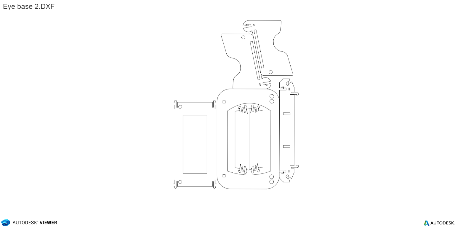
Software:
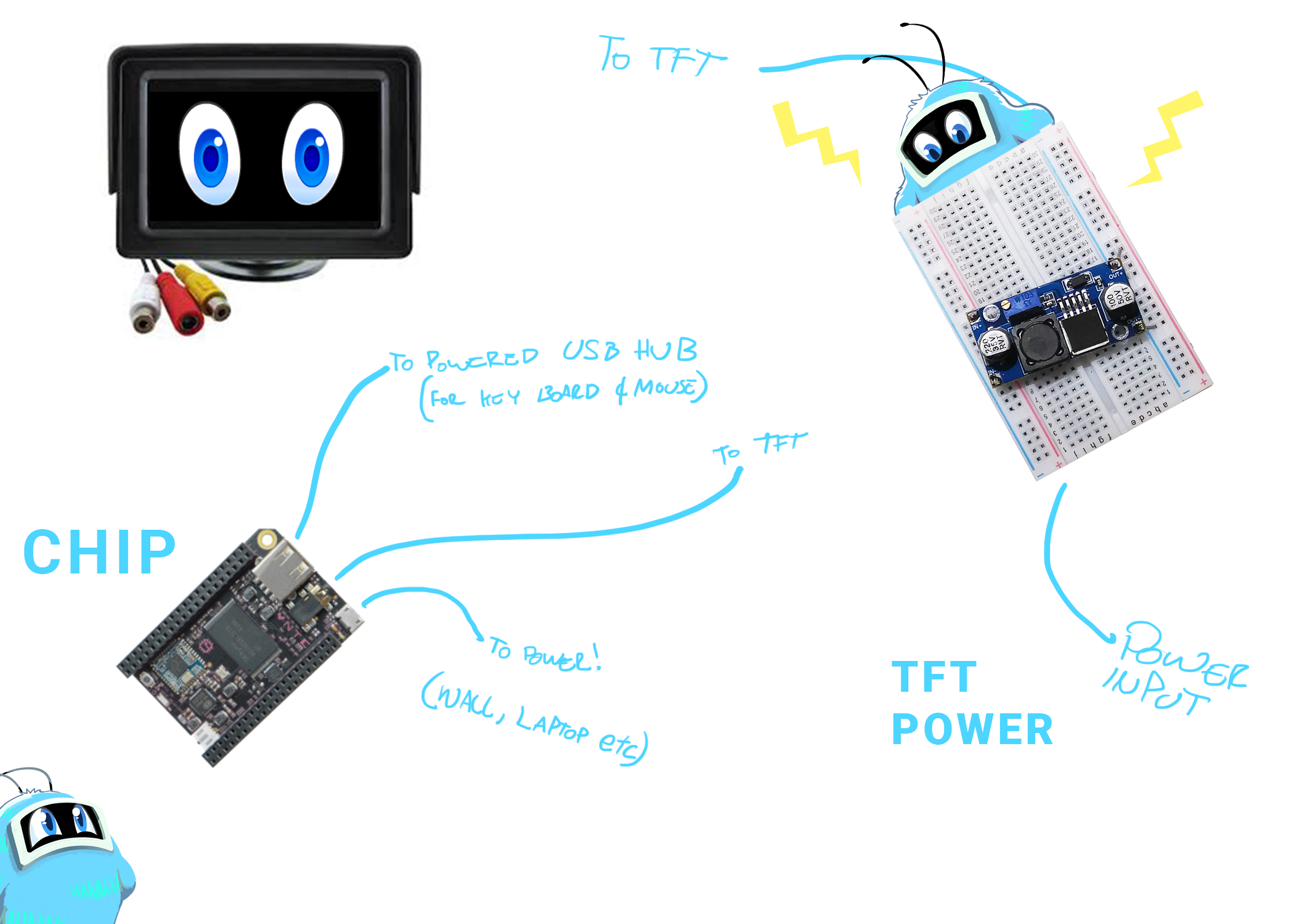
Figure out how to make mosquitto run on startup(!!!)
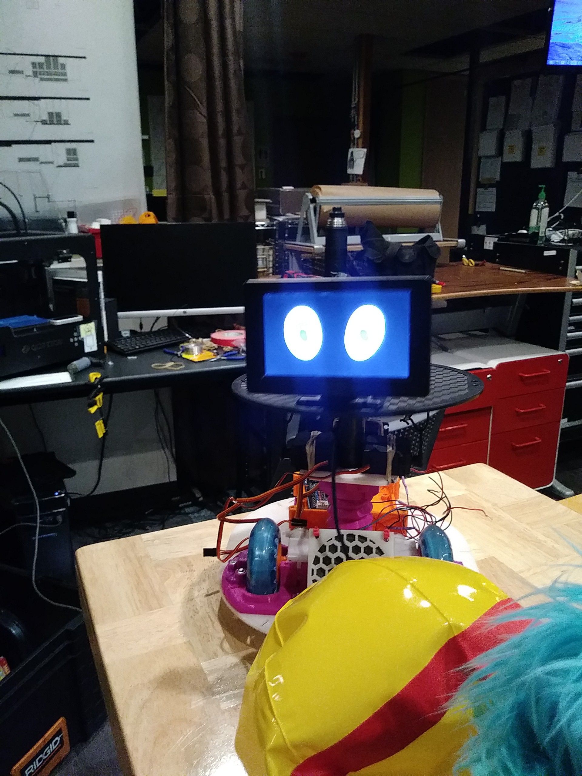
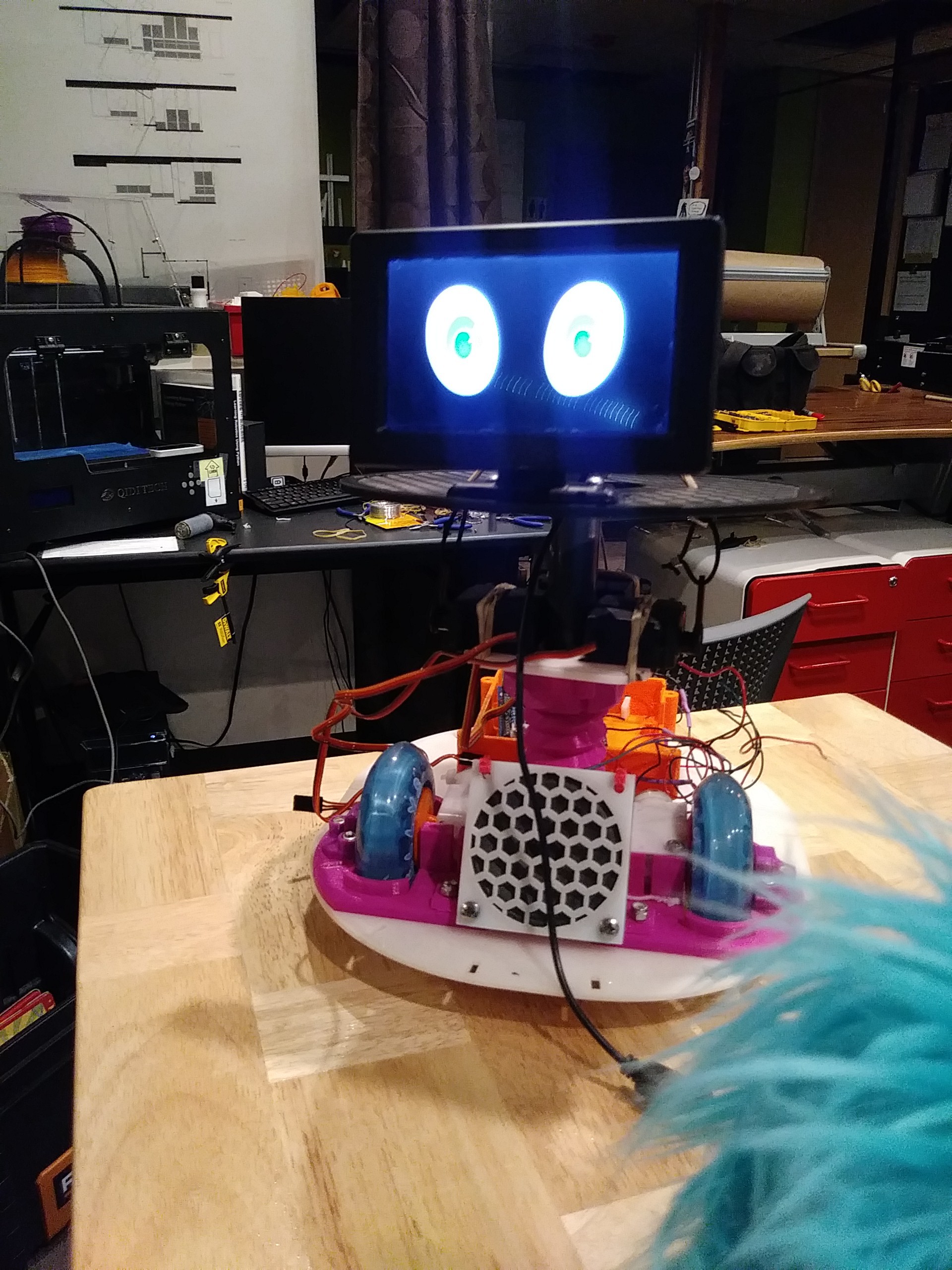
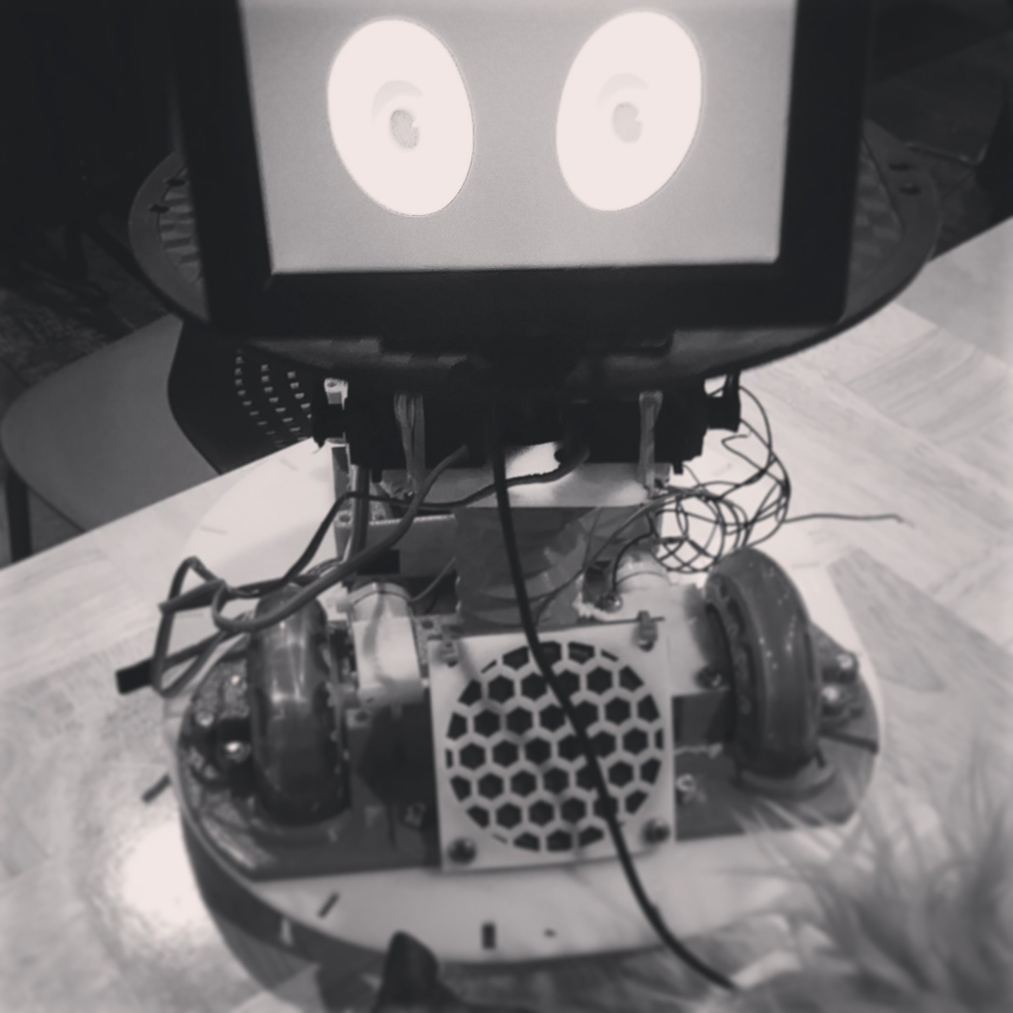
Figure out how to put splash screen on boot, so that Romibo's eyes doesn't look like eerie lines of codes
Figure out how to shorten loading time of eye animation pictures
Figure out how to add more emotions: Seems like not enough memory
Romibo_twitterpatted's current sequence of pictures needs work
Figure out how to have a better voice for Romibo
Figure out how to eliminate cut-off of first few words of audio
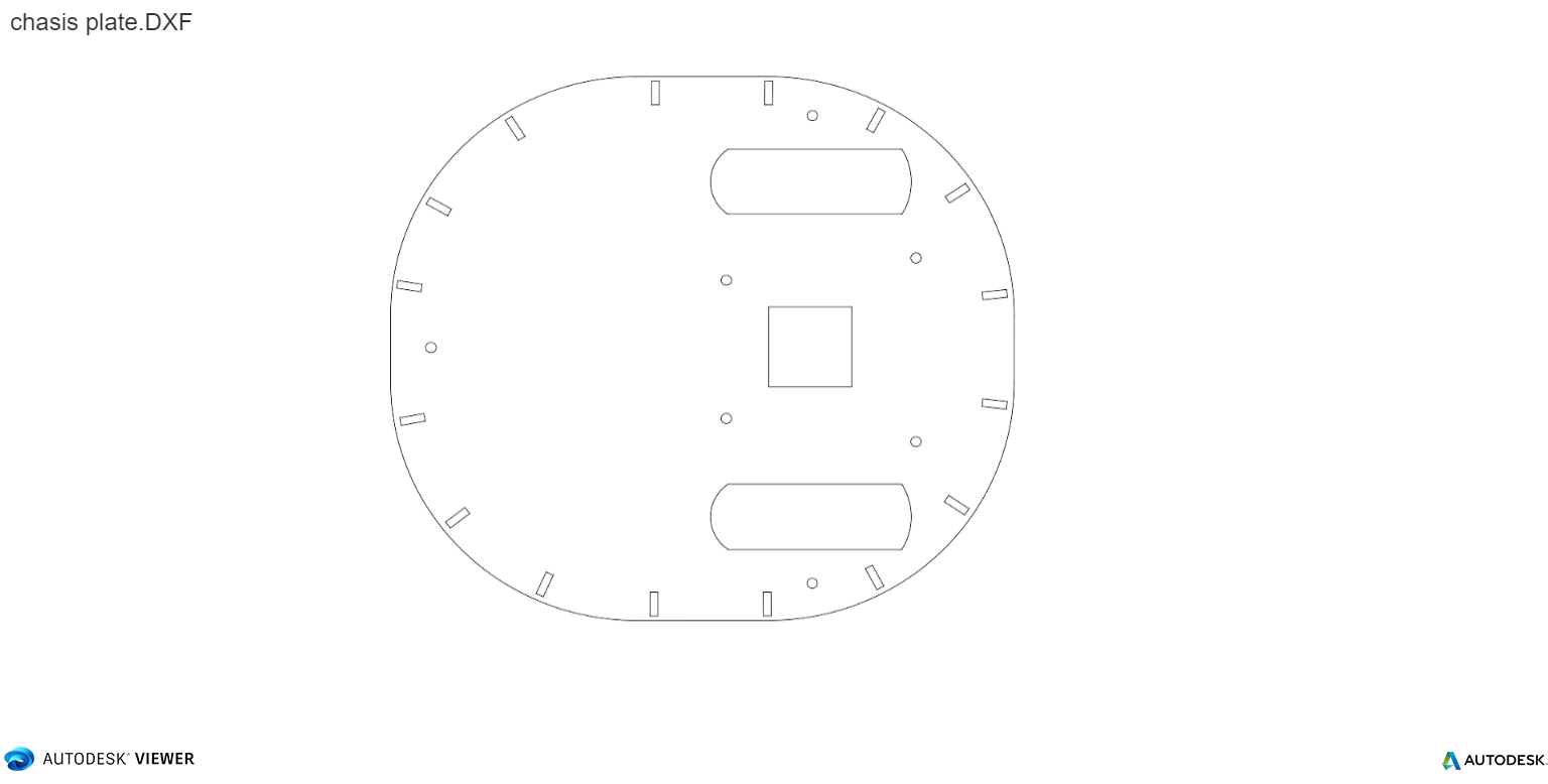
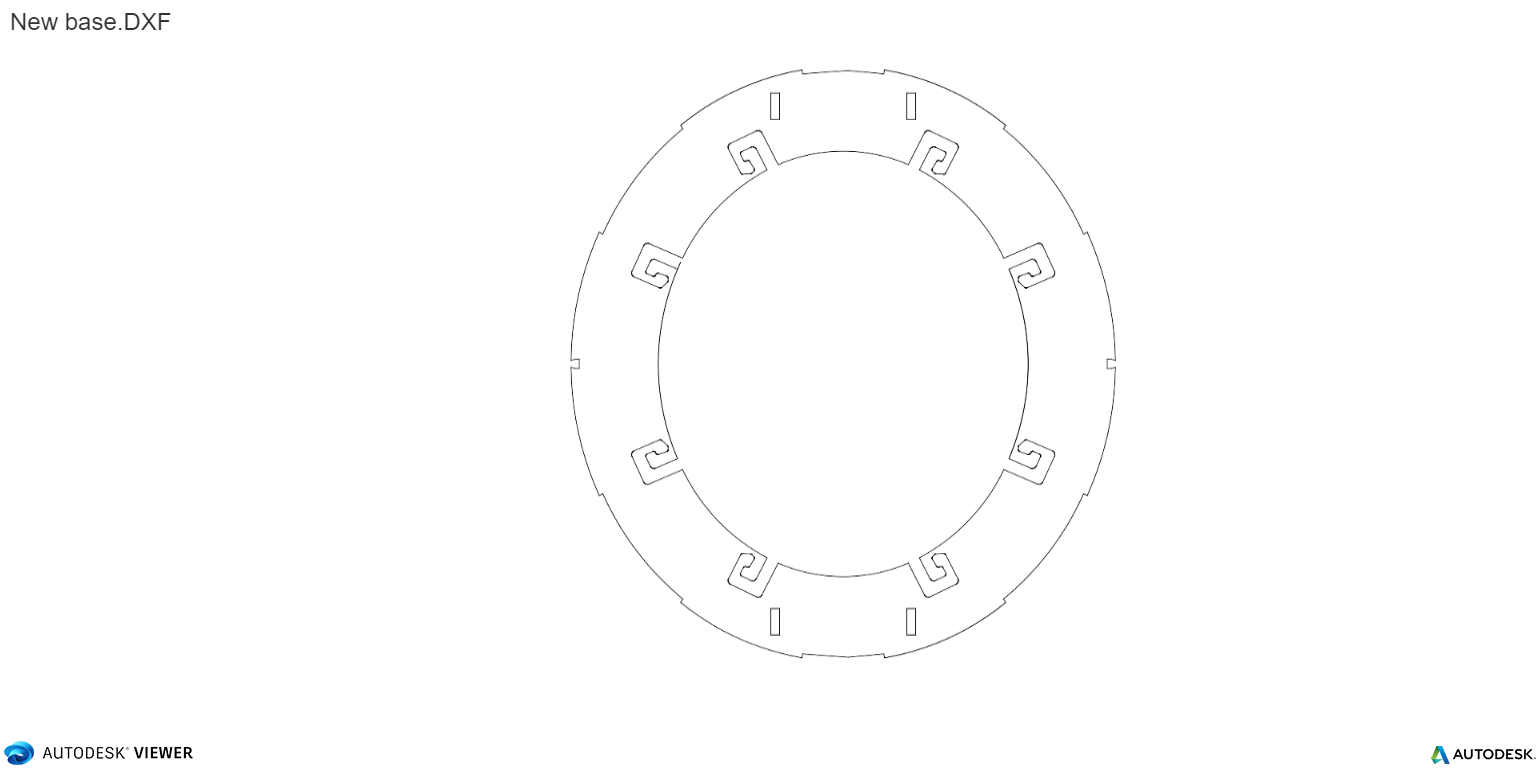
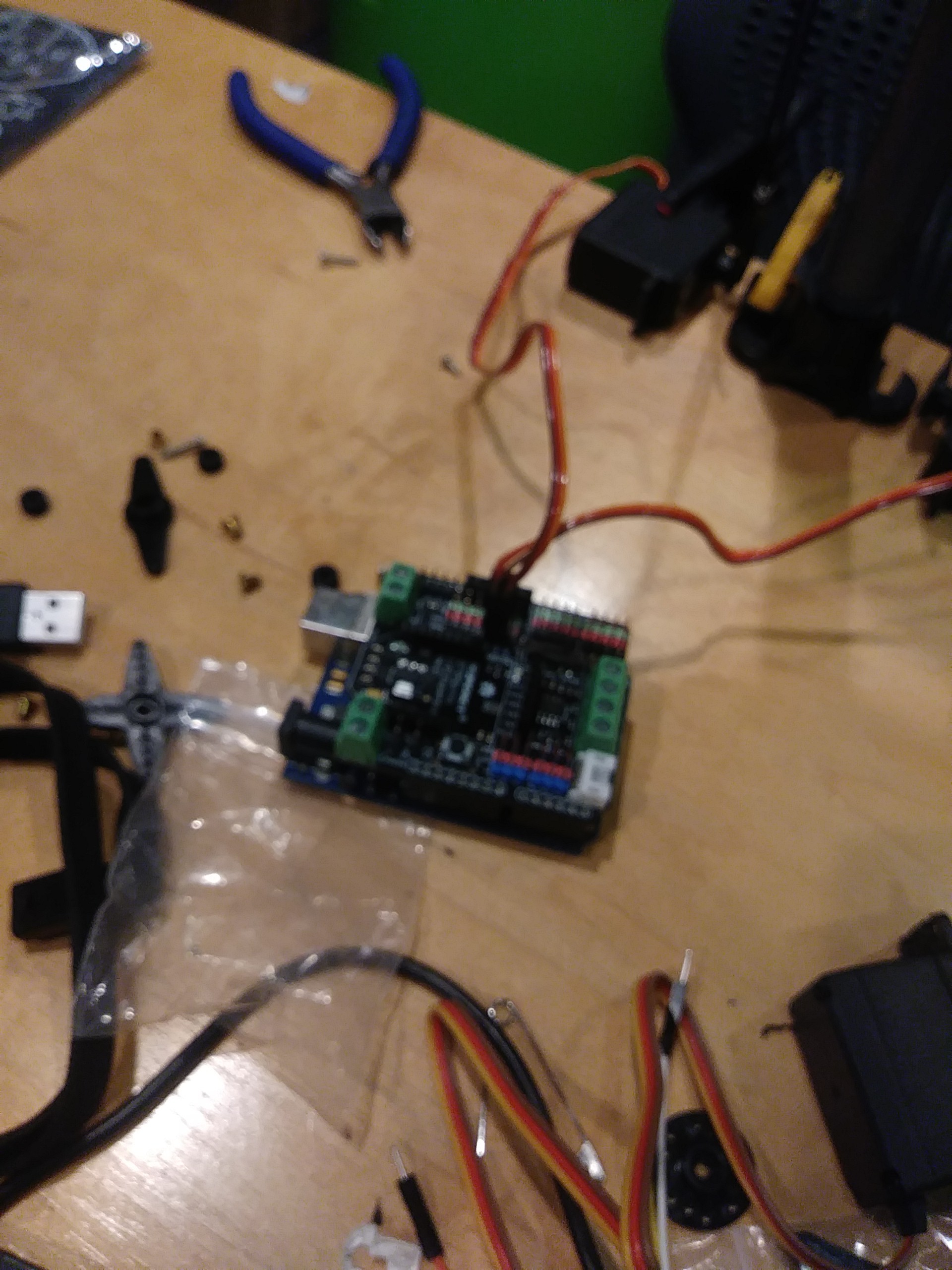
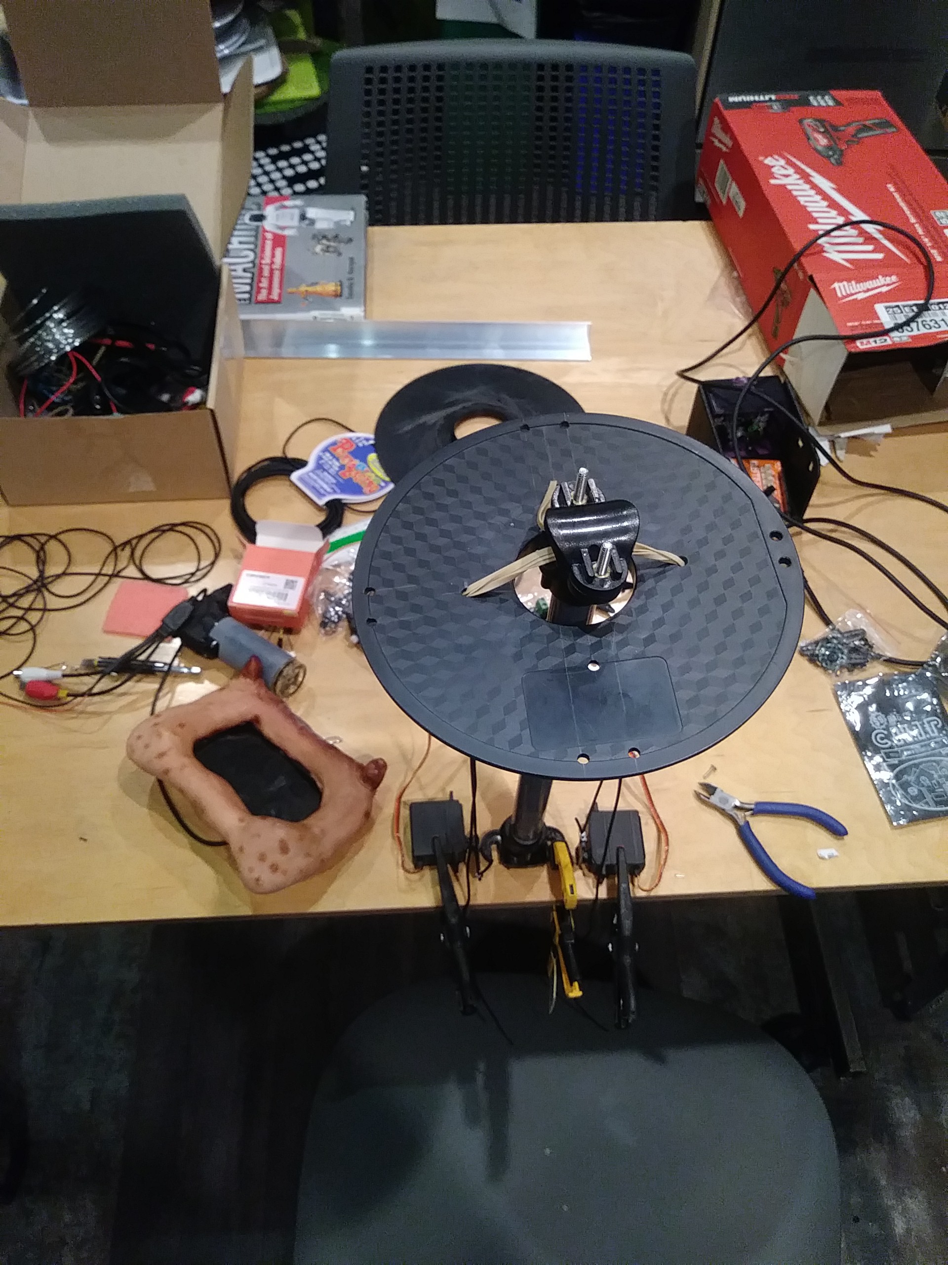
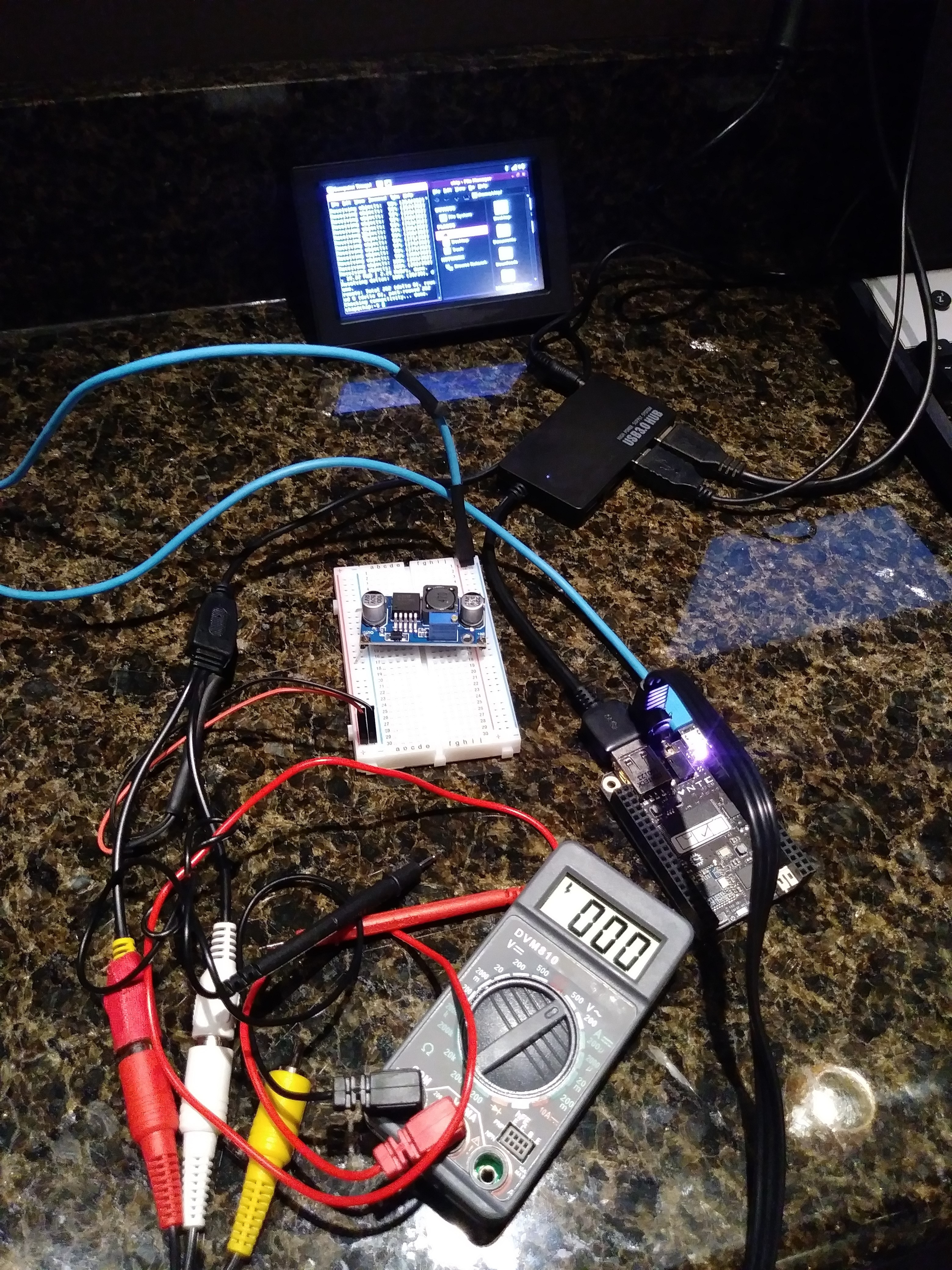
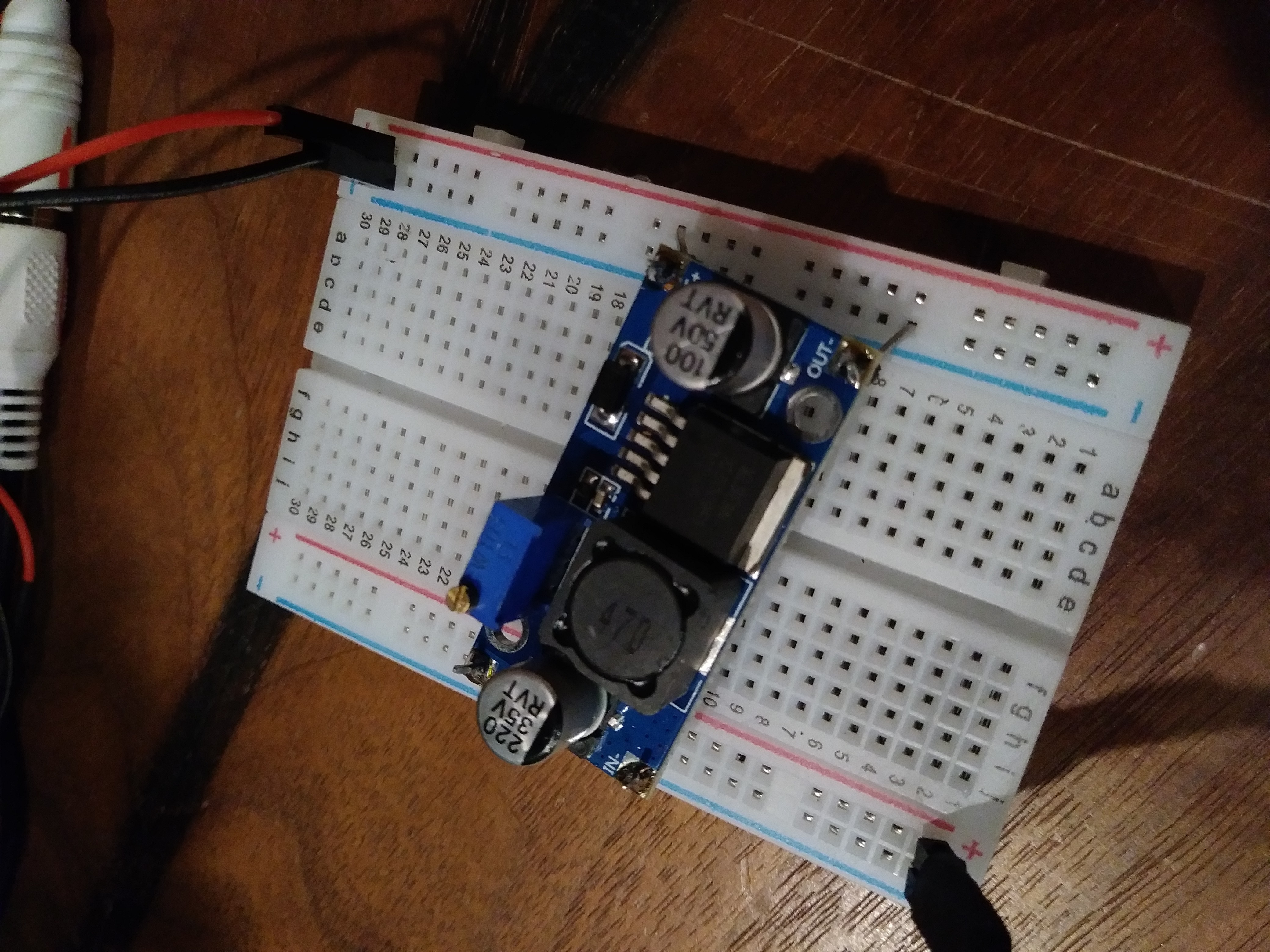
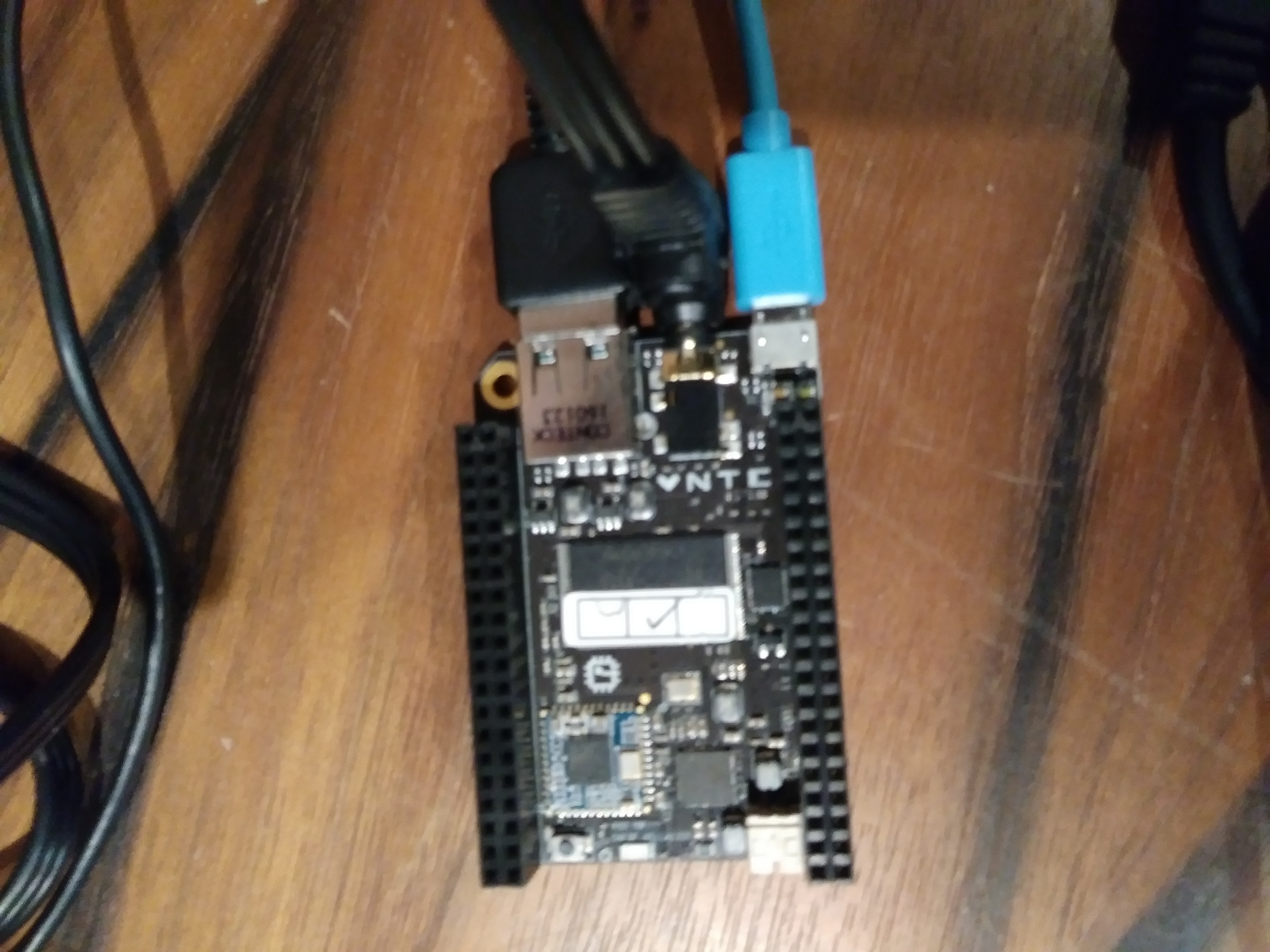
Hardware:
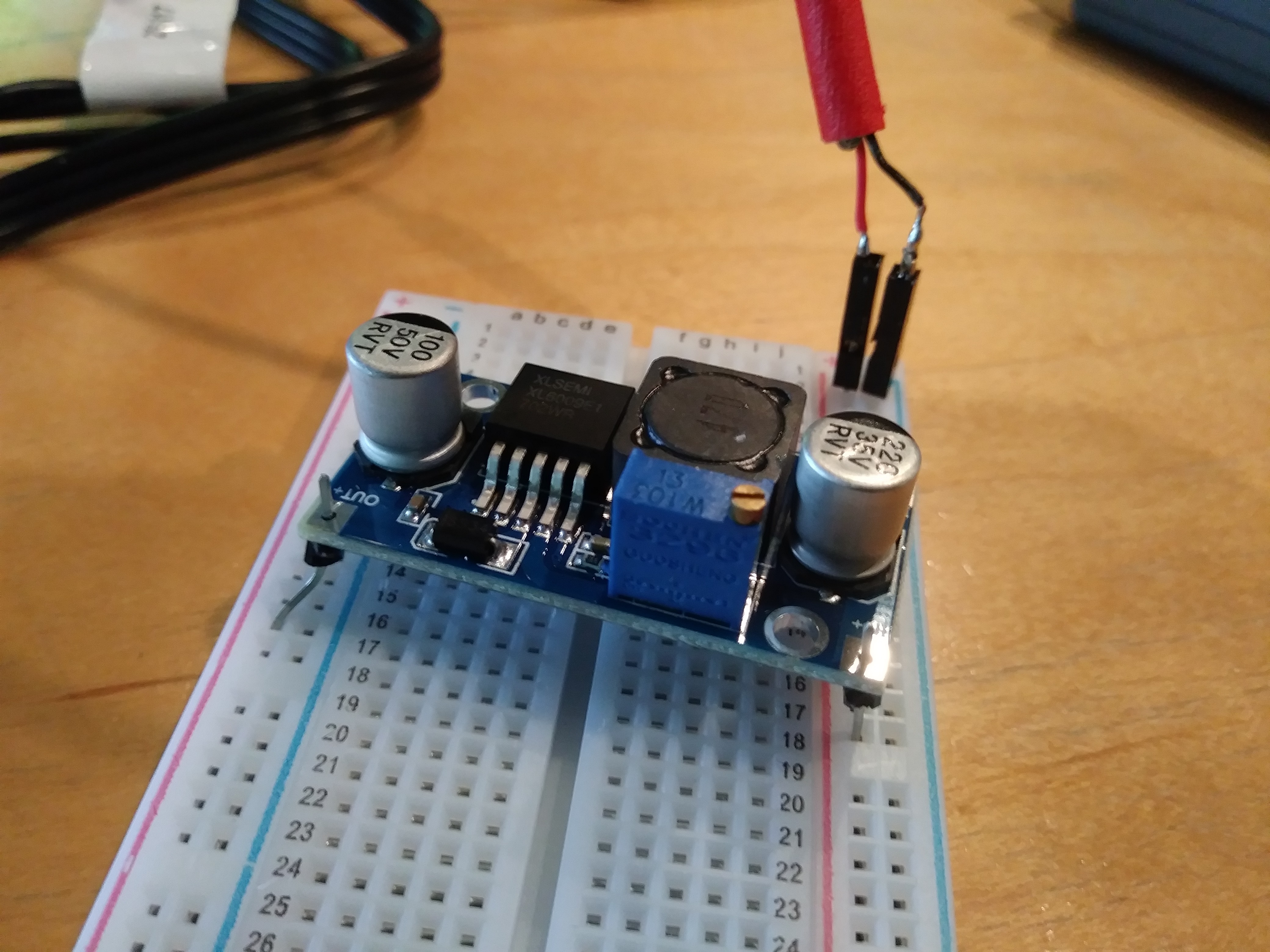
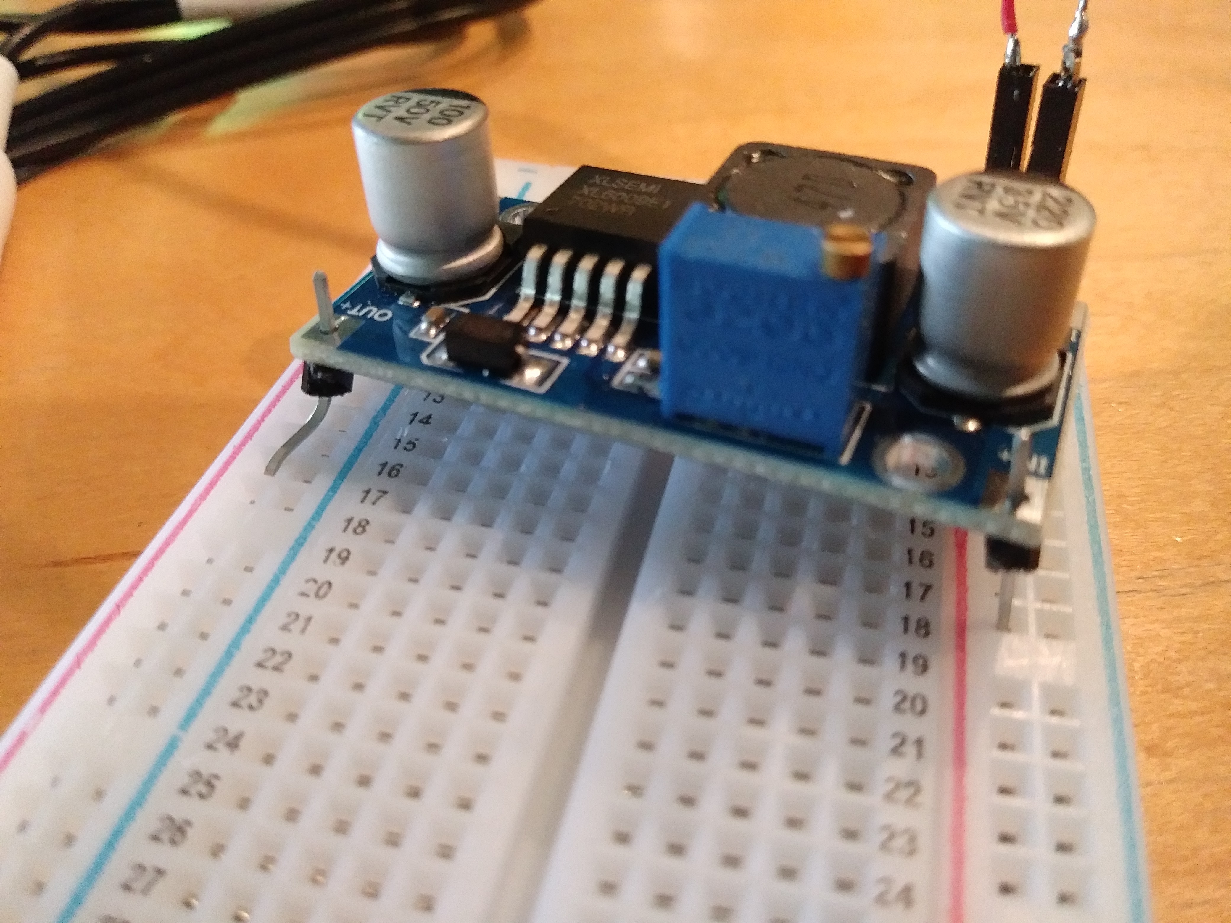
Figure out more reliable ways to connect wires
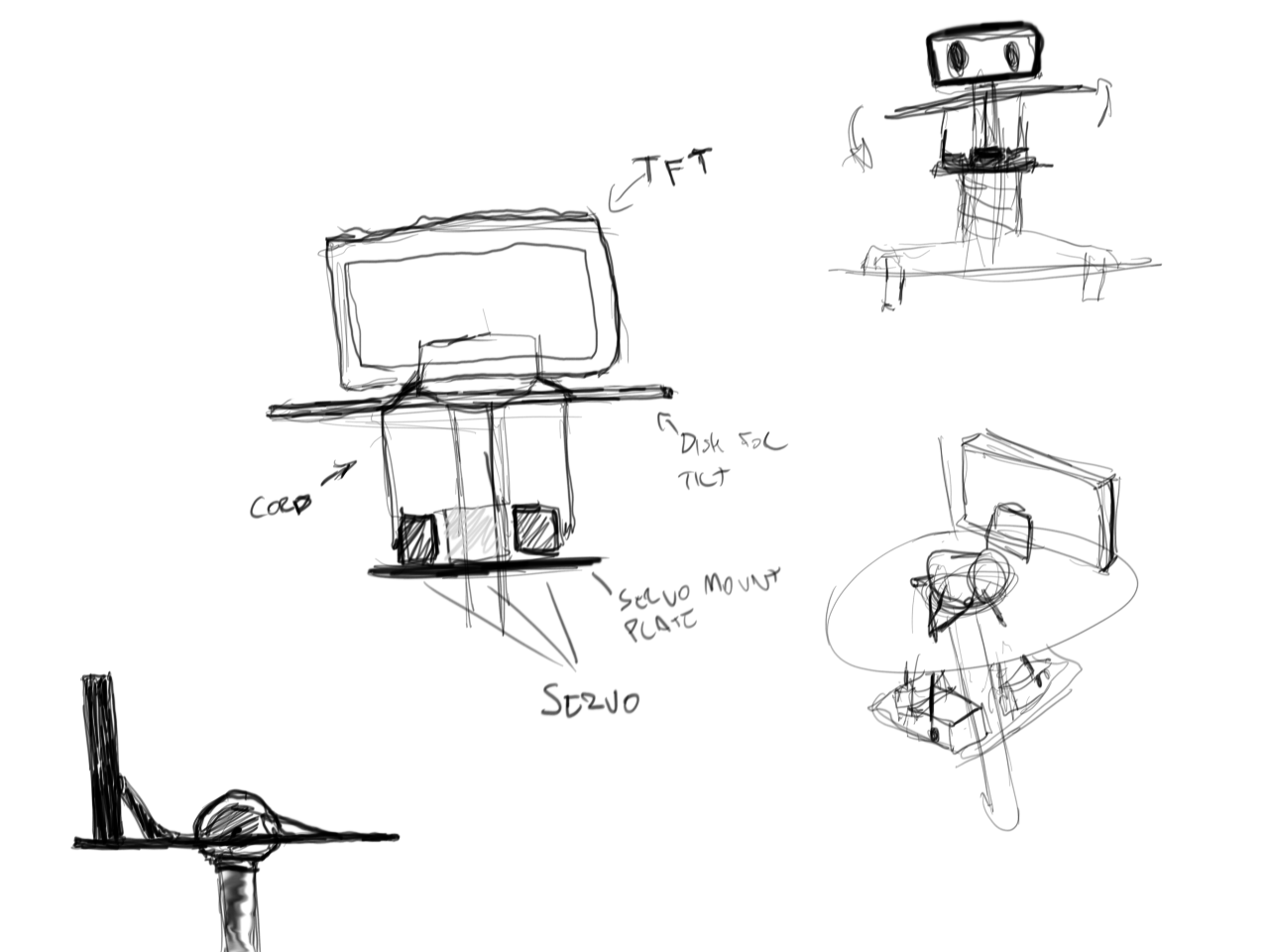
Figure out better ways of housing electronics
Figure out how to make motors more responsive
Figure out better ways of holding motor wheels in place

App:
Figure out how to replace Paho MQTT with cocoaMQTT, to eliminate apple store problems (!!)
Figure out how to preserve client existence when transiting between modals. The problem right now is that the connection resets each time a new button/palette is added.
Make the connect button fit the theme better.
Make a better 'instructions' page
Make an 'about' page.

More to come soon!

In the mean time, visit:
https://github.com/OrigamiRobotics/open

Enjoy.

#OpenRomibo

Graphics Interchange Format - 1.20 MB - 09/14/2017 at 05:21

Preview
Download

x-zip-compressed - 28.08 MB - 09/03/2017 at 17:42

Download

Adobe Portable Document Format - 2.27 MB - 09/03/2017 at 15:38

Preview
Download

Microsoft Word - 3.08 MB - 09/03/2017 at 15:38

Download

Microsoft Office - OOXML - Word Document - 2.42 MB - 09/03/2017 at 15:38

Download

View all 8 files

  • 1 × A CHIP and RCA cable (comes together in a purchase) https://getchip.com/pages/chip
  • 1 × 12V TFT Display Typically used in cars as reverse camera displays
  • 1 × Boost converter Able to convert 5 volts to 12 volts http://a.co/6eL7r2X
  • 1 × Bread Board
  • 1 × Two micro USB Cables (we will be cutting up one of them)

View all 12 components

  • A new face

    OpenRomibo09/03/2017 at 16:58 0 comments

    A friendly beezel cover. There could man many varioations either sculpted and casted or 3d printed. I have been in favor of traditional sculpting when possible. I would love to make a silicone cast to add to the softness of the entire robot. The freckles are a result of torching the polymer after baking.

  • Laser cut examples

    OpenRomibo09/03/2017 at 16:26 0 comments

  • Videos videos

    OpenRomibo09/03/2017 at 01:08 0 comments

  • Prototyping the head tilt mechanism

    OpenRomibo08/31/2017 at 05:33 0 comments

    This prototype rig was accomplished using recycled parts and a few parts from the local hardware store. The setup is equivalent to a 3 point head tilt axis. It was hard to find a system at this scale without blowing budget on custom rigs. I wanted something simple and lightweight that I could make quick modifications to to get the actions just right. I am building this head tilt system onto the established internal structure. The head tilt will be for very simple movement such as soft breathing or curious head tilts.  

    I am using 2 5kg servos for roll and a 20kg servos for pitch. The Arduino code currently is a simple modified servo motion loop with no interaction/sensor input as of yet.

    The head tilt mechanism uses standard 20kg and standard 5kg servos. 

  • Finding and powering the right TFT monitor

    OpenRomibo08/31/2017 at 05:28 0 comments

    Hello!!!!

    in Pictures and a fancy diagram, here's how to get that TFT powered. 

View all 5 project logs

  • 1
    Flashing the C.H.I.P

    When the CHIP comes brand-new, it doesn’t have an operating system installed in it. Hence the CHIP must be flashed before using.

  • 2
    Setting up the electronics

    We first need to modify the USB cable to supply 5V to the breadboard.

    • Cut one of the USB cables in half. This will expose either 2 or 4 wires of different colors. If there are 4 wires, we will only use the red and black wires. The red is positive and the other wire will be negative.
    • Strip the positive and negative wires.

    In the picture above, I added a male crimp end for a better connection
    • We’re ready to set up the boost converter! Connect the converter on the breadboard so that “IN+” and “OUT+” connect to the power pins,  “IN-” and “OUT-” connect to the ground pins.
    • Connect the modified USB cable, power cable (stripped) and the boost converter as shown below (positive matches with (+), negative matches with (-):

    • Connect the USB to a powered USB hub. Use the multimeter to check if the voltage between the inside and outside of the power head is 12v. You can tune the output voltage by turning the adjusting screw.
  • 3
    Connecting everything together

    Now start connecting cables with the CHIP, powered USB hubs/Laptop and breadboard:

View all 4 instructions

Enjoy this project?

Share

Discussions

isabellalake wrote 01/28/2020 at 13:10 point

Wow this is a cool educational project, a robot designed specifically for students, I would gladly investigate it. You may also like my educational project https://papersbattle.com/best-essay-writing-service-reddit/ , where you will find the best essay writing service reddit, the target audience of this project is just students, so I think that you will be interested.

  Are you sure? yes | no

Similar Projects

Does this project spark your interest?

Become a member to follow this project and never miss any updates