-
1Step 1: Set up the ESP8266
Get the MicroPython firmware running on your ESP8266. Here are some instructions if you've never done that before. You will need a module with at least 1 MB of flash and 3 free GPIOs. Your old ESP-01 probably isn't going to cut it, sorry.
Download the Python code from my GitHub: dracode
Once you've got the firmware running, upload the Python code. I use webrepl_cli.py to upload my files.
-
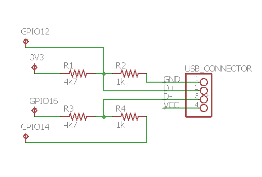
2Step 2: Build voltage dividers
![]()
I used a standard USB-A connector that would plug into the QC3.0 port on my power bank. I just cut an old cord and re-used it. The black wire is ground, red is positive, white is the "D-" line and green is the "D+" line.
I used 1kΩ and 4.7kΩ resistors to create voltage dividers that I could control with a microcontroller. With a voltage of 3.3V on top of the bridge, that would give me right around 0.6V in the middle. According to the data sheet I used, the signals levels we need are: 3.3V, 0.6V, 0V, or disconnected.
I used a 3.3V microcontroller in the project. It's VERY IMPORTANT that you do NOT hook the microcontroller up to the positive wire coming out of your QC3.0 USB connector! We're about to ask the power bank to provide up to 20V on that line, which will surely fry your microcontroller. I used a separate 3.3V power source in this proof of concept project, but in real use you would probably want to use a 3.3V voltage regulator to safely get power from the variable-voltage QC3.0 source.
-
3Step 3: Try it out
Plug in your QC3.0 power bank/charger/whatever and turn it on (if it has an on button).
Run the example.py script you downloaded from GitHub.
Profit?
Quick Charge 3.0
An device-side implementation of the new modes from the Quick Charge 3.0 protocol to provide voltages from 3.6-20V in 0.2V increments
Discussions
Become a Hackaday.io Member
Create an account to leave a comment. Already have an account? Log In.