 Julien
The computer is composed of :
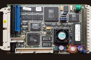
- A Beagleboard X15, with a strong ARM CPU (TI AM5728)
- 128Gb SSD hard drive
- VoCore2 SBC for Wifi
- A cheap aluminium briefcase and some aluminium plates
- A 15" LCD panel (including a breakout board)
With that, I made myself :
- The keyboard, STM32F0 controlled board with CherryMX keys and lighting (https://github.com/julbouln/stm32_mech_keyboard)
- A TTL to LVDS interface with the Beagleboard X15 (https://github.com/julbouln/x15_ext1)
- An ethernet breakout for the Vocore2
The project is incomplete yet, I still want to add a battery, and a touchpad.
 Keith
Keith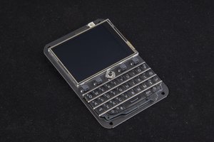
 arturo182
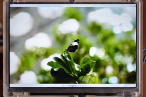
 tshen2
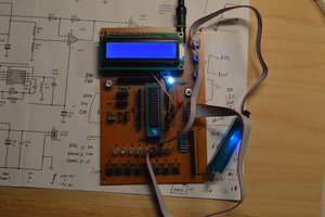
 w_k_fay