Close
0%
0%

S.A.M.I.R.A.

Synchronous All-Purpose Minimal Instruction Reckoning Apparatus

Similar projects worth following
A simple but yet fully functional and turing complete 8-bit computer i built for learning purpose. I designed it over the last few years, simulated it in Logisim and built from CMOS 4000 and TTL 74 series integrated circuits. The circuit is already fully functional and can compute any mathematical problem, as long as the code is small enough to fit in the 255 bytes of memory. Code is entered through a 70s-style front panel with LEDs and flip switches. It features 14 Instructions and can run at almost 1Mhz so far.

Be sure to check out the logs and the video demo
https://www.youtube.com/watch?v=djOr23mgWfY&list=UUJRcwdOIXHrseSverdiru-Q
as well as the follow-up project:
https://hackaday.io/project/11644-samira-mk-ii

SAMIRA is a 8 bit RISC accumulator machine without microcode, which means it only has one working register, the accumulator. The result of every calculation is automatically stored back in to the acc. Every instruction consists of two bytes, the first byte specifies the operation to perform, the second byte contains the operand. The operand byte can be data or an adress. This keeps the hardware and the decoder fairly simple.

The basic elements of the CPU are:

CLK - the master clock, step and auto
SEQ - the sequencer, performs the instruction cycle
DEC - the decoder, controlls most control lines in the CPU
RAM - the main memory, holds code and data
PC - the program counter, holds current program position
IR - instruction register, holds the current instruction
OP - operand register, holds the current operand
A - the accumulator, the one and only main working register
ALU - arithmetic [logic] unit, performs calculations and jumps
IN/OUT - basic IO interface

The 14 instructions are:

NOP - does nothing but wait
LD - loads operand byte to acc
LD$ - loads byte from adress, to which operand points, to acc
STO - stores acc to adress to which operand points
ADD - adds operand byte to acc and stores back to acc
ADD$ - adds byte from adress, to which operand points, to acc
SUB - subtracts operand from acc
SUB$ - subtracts byte form adress, to which operand points, from acc
JMP - jumps to adress specified by operand (loads PC)
ZRO - jumps if A not equal to 0
MSB - jumps if MSB (most significant bit) is not set
CAR - jumps if carry flag is not set
IN - loads byte from external device to a
OUT - writes byte from a to external device
The flags of the conditional jumps are inverted to make loops easier.
Due to the simplicity of the decoder the corresponding hex values for the commands are quite odd.

The ever repeating instruction cycle is:

FI - fetch instruction
INC - increment pc to next adress
FO - fetch operand
INC - increment pc
DEC - decode instruction, decoder sets all control lines
EXE - command is executed, registers are modified
The seperation of DEC and EXE was done to give the bus lines time to settle, prevent race conditions and provide stability.


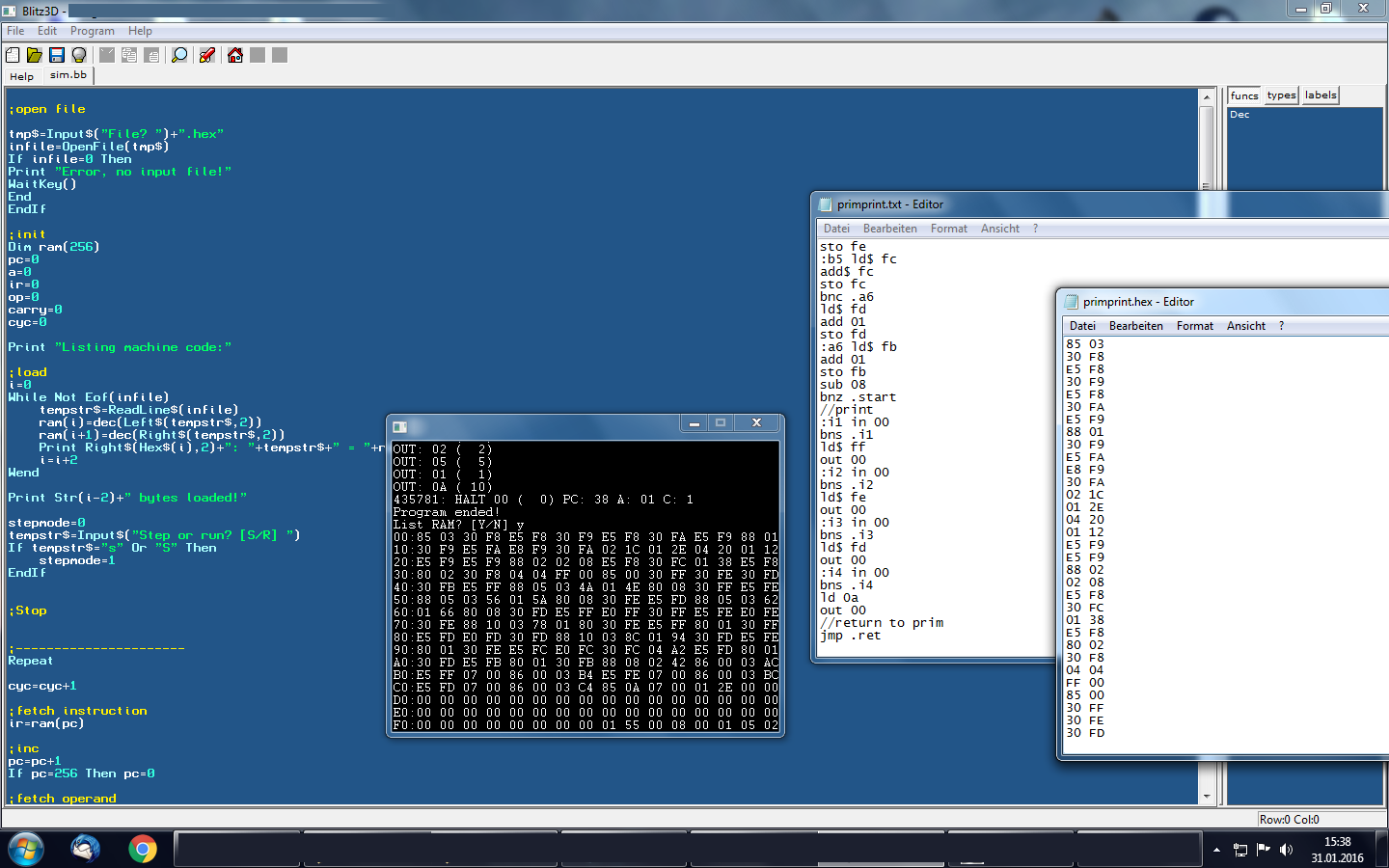
The following simple program counts down from 100 (0x64) to 0 and then ends in a loop:

ADR CMD

00: LD 64
02: SUB 01
04: ZRO 02
06: JMP 06

  • 12 × 74244 8x tristate buffer, used as multiplexers
  • 1 × 628128-70 128K X 8 main memory
  • 20 × BAT43 schotky diode, used as OR gates
  • 2 × 74283 binary adder, used in ALU
  • 2 × 74161 loadable counter, used as PC

View all 18 components

  • Log0A

    0xCAFEAFFE05/10/2016 at 07:51 0 comments

    I finally uploaded the video of the CPU calculating and printing out prime numbers :)

    It took me like an hour or so, to punch in the opcodes through the flipswitches! :D
    I consider this project complete now and I already designed a slightly improved version, which i will build over the next few months (or years). I hope that i will be able to document it better, from the beginning on.

    Here is the link to the (now still empty) project page:
    https://hackaday.io/project/11644-samira-mk-ii

  • ​Log 09 - Software

    0xCAFEAFFE01/31/2016 at 14:59 0 comments

    Last night I wrote a dirty little two-pass assembler and an emulator, which makes it a whole lot easier to write and test software for my machine!
    The 'driver' software for my printer, that converts binary numbers to binary coded decimals (+ polling the busy-line of the interface + writing out the data) is working, the (very slow and crude) prime finding algorithm is done too!
    It looks like everything is ready to go! Now all I need to do is to load the code into the machine through the binary interface, debug and run it - which will probably take me an afternoon! (code already takes up ~200bytes = 4/5 of the main memory)

    My baby will finally proove its's usefulness :D I'll post another video once it works! (timelaps might be necessary hehe)


  • Log08 - Video

    0xCAFEAFFE01/19/2016 at 07:36 0 comments

    IT'S ALIVE!! The zombified calculator-printer works! :)
    Up next: proper software (binary to decimal conversion, fibonacci numbers, primes, ...)

  • Log06

    0xCAFEAFFE01/12/2016 at 11:11 0 comments

    I started this project because I wanted to know, on the lowermost level, how a computer works. After I designed the machine in Logisim, I was not sure if it would work in hardware at all and had almost no experience with digital circuitry, so this is why I rushed into some things that I could have planned better.
    What I learned from this project so far:

    1)
    It is easy to design a digital circuit on paper, harder in Logisim, fairly easy to build on breadboard but a nightmare to solder it to a circuit board.

    2)

    As you can see, my first circuit board looks like sh*t :D
    This is, because the usual soldering technique, where your wires are soldered on the bottom of the board but come out the top, is not suitable at all for this number of connections. It is extremley confusing to turn the board around all the time for making the connections. You easily loose your sense of orientation and end up making wrong connections. I hope I never ever encounter any serious hardware problems with this machine, I'd rather build a new one than try to debug this! And if I build another machine (which is likely) I will probably try wire-wrapping it.

    3)
    Neither normal solid nor stranded wire is suitable for making connections. Solid wires are not flexible enough and take too much space, stranded wire easily breaks at the soldering points. I ended up using AWG30 wire wrapping wire. It is small in diameter, flexible and does not break so easily.

    4)
    The momentary switches I used, are not suitably for this project. They bounce like mad and eventhough I added capacitors and even schmitt-triggers, they still do. I'll have to use other switches next time, test their bouncing behavior in advance, and design proper debouncing circuits as well.

    5)
    I have to design a proper mechanical system in advance as well, to keep the circuit boards in place. I still don't know how to do this now. I don't have space left to drill holes into the boards and gluing them into the casing is ugly. Next time I will not connect the boards with wires directly, but plug them onto a main board whose purpose it is to interconnect the seperate boards and provide a mechanical connection.

    6)
    I should have spent a little more time to pick the integrated circuits i used, the registers on the first board, as well as the RAM for example are unnecessarily big, if i only used edge-triggered circuits, i could have left out the DEC-step in my decoding sequence.

    I'll update this if something else comes to my mind!

  • Log05

    0xCAFEAFFE01/10/2016 at 22:34 0 comments

    You can probably already guess what's going on here ;)
    I found an old calculator that also has a small printer built in! So after quite a while of not touching this project, I finally have a good reason to work on it again! This printer is a perfectly suitably extension for my IO interface! I already took the calculator apart, now I am 'hacking' it, will wire it to some glue logic so i can hook it up to the interface and finally do something useful! Like calculating and printing out primes for example! I'll shoot another video when it's done :)

  • Log04

    0xCAFEAFFE07/23/2015 at 22:03 0 comments

    WHY AM I SO LAZY?! Sorry. :D

    The computer is almost finished for a while now, but i was to lazy to upload my progress!
    I also still need to complete the casing, but from an electronic standpoint everything is done :)
    Maybe i'll find some time in the next few days to finish up everything and upload the most recent pictures!

  • Log03

    0xCAFEAFFE11/30/2014 at 20:46 0 comments

    Second Stripboard almost complete! :) Transfering the circuit from breadboard to stripboard, wiring and soldering it takes an incredible amount of time. The new wiring/soldering techique slightly reduced that time, but it still took far longer than building the the CPU on breadboard! But im almost done now! All that is left to do is implement the STO instruction (3 control lines and 1 databus to connect) and IO operations, then add another multiplexer for reading out the accumulator through the front panel, connect the instruction status leds and pack everything into one case.

  • Log02

    0xCAFEAFFE10/19/2014 at 13:11 0 comments

    The second board is finally taking shape! I'm using a new wiring technique as described here:

    http://www.instructables.com/id/How-to-Prototype-Without-Using-Printed-Circuit-Boa/
    TLDR-Version: I am using AWG30 wire for making point-to-point connections on the solder side.

    You have to prepare the wire and also work very carefully (not to burn off the insulation of any nearby wires for example) but you are rewarded with a much higher circuit density that is actually less chaotic! Therefore the additional work is worth it!

  • Log01

    0xCAFEAFFE08/26/2014 at 10:50 0 comments

    I just seperated the two parts of the CPU, the fully assembled and solderd, and the part still on breadboard. In the next few days i will solder the remaining parts on stripboard and soon the CPU might be finished and will be fitted into a case.

  • Log00

    0xCAFEAFFE08/21/2014 at 11:41 0 comments

    The current status is as follows:
    Design: 100%
    Simulation: 100%
    Front Panel: 90%, one switch not functional yet, status LEDs in the upper right not connected
    Hardware: 80%, IO not done yet, 2/3 of the hardware solderd on stripboard, rest still on breadboard.
    Soldering: 50%

View all 10 project logs

  • 1
    Step 1

    Just accquire some integrated circuits, solder them together and load up a program! It's really not computer science! Oh wait, it is..

  • 2
    Step 2

    I will not publish build instructions as it is a far to complex project to identically replicate and you would probably not understand my (arbitrary) design desicions in the background anyways. It is also not a very useful machine to build, but very useful for learning purpose.
    I don't even have complete circuit schematics and i would not built the machine differently if i did it all over again! If you want to build a similar computer you will have to aquire skills in digital logic and computer architecture and make up your own design to fully understand it.

View all instructions

Enjoy this project?

Share

Discussions

ATmel91 wrote 12/08/2019 at 12:26 point

Hello! Can you provide your logicism file so I can test my own circuit? Thanks!

  Are you sure? yes | no

Justus Hausmann wrote 05/11/2016 at 19:43 point

sorry if i am asking dumb but i am working on a CPU too and i'm almost finished with testing in logisim but i don't have a clue how to check how the circuit will act in real world with real components... so my question how have you done your theoretical circuit simulation?

  Are you sure? yes | no

0xCAFEAFFE wrote 05/12/2016 at 10:32 point

Not dumb at all :) The same question bothered me when I started this project, I had no idea if my design would work. I realized the only way to find out was to just try and build it! I began with doing some experiments on breadboard, of course you have to adapt your circuit to the real existing integrated circuits. Gates work just like in the simulation, almost ideal, things like RAM can be a bit more tricky because they may have additional inputs like 'output enable', 'input enable', 'chip select' and so on, or require specific timing (check out the datasheets), some chips require active-low enable or reset signals, but if you keep these things in mind your design will work just like in the simulation :)

  Are you sure? yes | no

Justus Hausmann wrote 05/12/2016 at 14:59 point

alright thanks 

i am ordering my stuff in some months or so and then the real madness begins ;D

  Are you sure? yes | no

dave wrote 01/12/2016 at 19:52 point

That is so nice, and I bet you really learnt a lot doing it...

  Are you sure? yes | no

0xCAFEAFFE wrote 01/13/2016 at 16:09 point

Thank you :) And yeah, I did learn a lot indeed! I will probably apply this new knowledge in my next computer project ;)

  Are you sure? yes | no

Similar Projects

Does this project spark your interest?

Become a member to follow this project and never miss any updates