Overview
This project uses the W1209 thermostat board, readily available for under $2. What I did was make a few small modification to the board:
- remove the 20k smd resistor next to the sensor connector,
- throw the sensor in the junk box,
- add a 10k resistor across the sensor connector (underneath if a smd resistor or remove the connector if using a through hole resistor)
- add a 30k resistor (or two 15k resistors in series) from the upper terminal of the sensor connector to the +12v rail.
Then I built a 1A constant current load from a 5v regulator and two 10 ohm resistors. You probably have those in your junk box ready for a project like this.
At present my board works as follows:
- after connection to the battery I hit the "+" key to run the measurement routine. It takes about 1 second and in that time it reads the battery voltage 32 times, summing the result, activates the relay which increase the current drawn by 1 amp and takes a further 32 measurements of the battery voltage summing those results, releases the relay then saves these two sums into eeprom
- I then hit the "set" key and the display shows me the average of the open circuit voltage, the loaded battery voltage, and the calculated internal resistance.
- If I hit the "-" key the run counter is reset to zero.
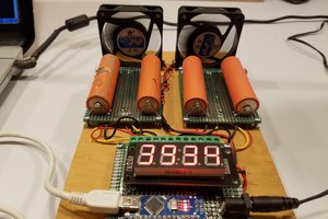
The current partially discharge battery I tested this project on had a beginning voltage of 12.8V, a loaded voltage of 12.5V, and an internal resistance of 0.2 ohms. Why not 0.3 ohms? That's the result of scaled integer maths. The 0.2 ohms is the correct answer. e.g. 12.81 - 12.59 = 0.22. But the display only shows voltage truncated to 0.1v.
My longer term goal is a test fixture that repeats daily a charge of the battery, measure the internal resistance, then applies the pulse conditioning until it is time to start the cycle over again. Then once every 8 weeks I can either dump the data back to the PC by reading the eeprom, or read the data via the display for whatever run I chose.

 Daren Schwenke
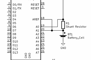
 Matthew James Bellafaire
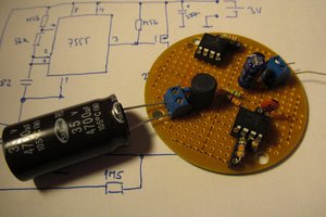
 jaromir.sukuba
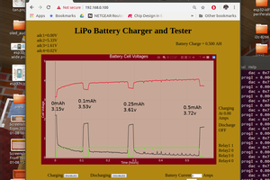
 markwarren.ee
Hey, that's interesting - I like to see real-world projects with Forth for STM8 used!