 agp.cooper
A Demonstration Program for a One Bit CPU
I was thinking about a suitable demonstration program for a one bit CPU.
My design has 4 inputs, two memory bits and 5 outputs.
Long time ago a friend had three 4PDT switches and two LEDs wired up to count the number of switches that were on. It was an interesting exercise to workout how he wired them up. Sounds like a great demonstration program for a one bit CPU, count the number of inputs that are switched on.
Well I started writing code with pencil and paper when I realised this is a logic minimisation problem.
The Truth Table
Here is the truth table:
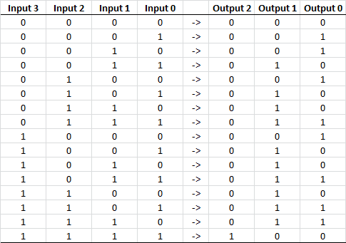
Here are the truth table equations:
C2 = A B C D;
C1 = A' B' C D + A' B C' D + A' B C D' + A' B C D + A B' C' D
   + A B' C D' + A B' C D + A B C' D' + A B C' D + A B C D';
C0 = A' B' C' D + A' B' C D' + A' B C' D' + A' B C D
   + A B' C' D' + A B' C D + A B C' D + A B C D';
The equations can be minimised (a little):
C2 = A B C D;
C1 = A C D' + A C' D + A' B C  + A B D' + B C' D + B' C D;
C0 = A B' C' D' + A' B C' D' + A' B' C D' + A B C D'
   + A' B' C' D + A B C' D + A B' C D + A' B C D;
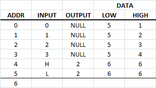
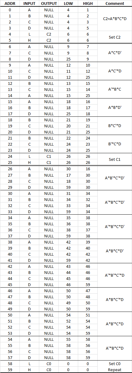
From the minimised equation I can now write the code directly. Here is the code to set C2 (Output 2) where A-D = Input 0-3:
I have not finished writing the code but it looks like about 80 lines of code.
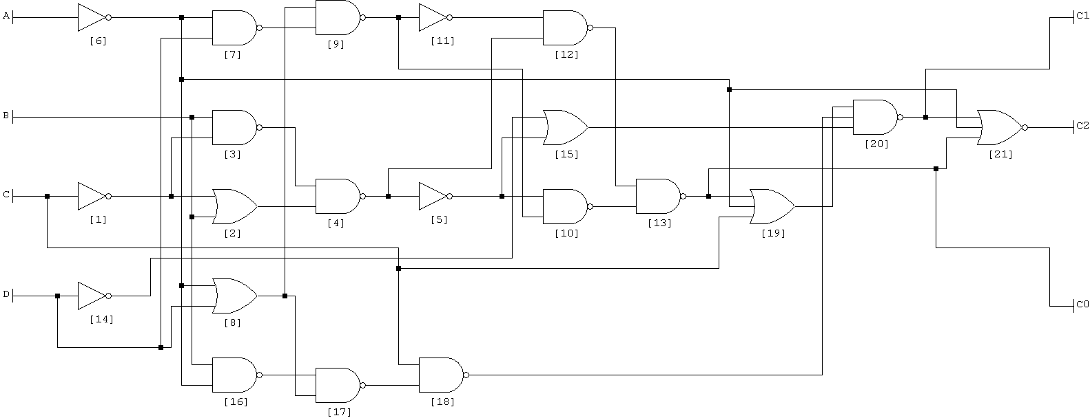
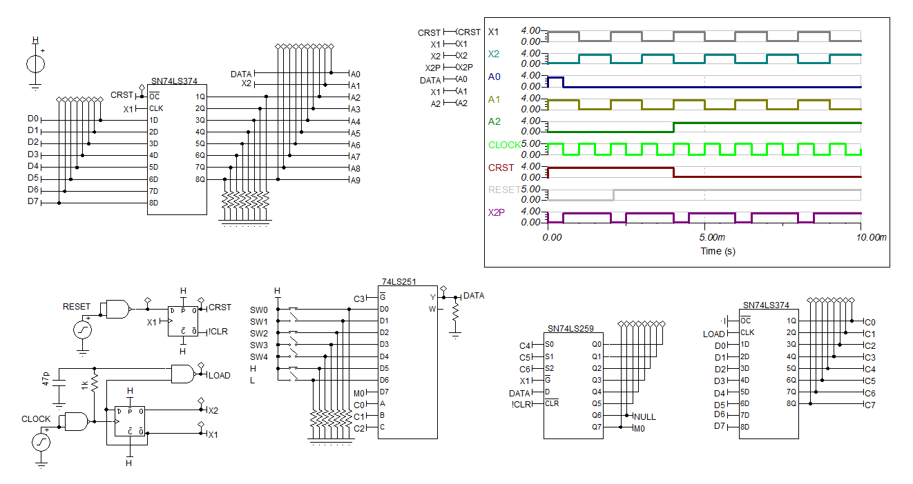
This is the schematic that Logic Friday came up with (scary!):
Completed Program
This morning I completed the code for the count program. Once you get the "hang" of the code it is pretty easy:
My coding approach is more finite state machine style, I did not use the memory bits.
Reworked the Simpler One Bit Version
I did not find any advantage in the more "complete" one bit CPU version. So I reworked the simpler version:
 (Note: The NAND gates are schmit triggers)
I dropped one of the memory bits as the programming style is more finite state machine (FSM) than procedural.
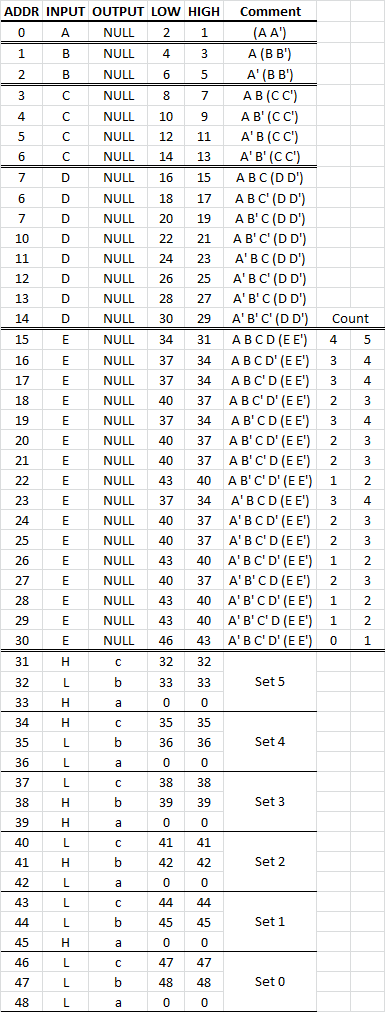
Now I will have to do a 5 bit count program! Here are the minimised truth table equations:
C2 = B C D E + A C D E + A B D E + A B C E + A B C D ;
C1 = A' B' C D E + A' B C' D E + A' B C D E' + A' B C D' E
   + B' C' D E + B' C D E' + B' C D' E + B C' D E' + A C' D E'
   + B C' D' E + A C' D' E + B C D' E' + A C D' E' + A B D' E';
C0 = A' B' C' D E' + A' B' C' D' E + A' B' C D' E'
   + A' B C' D' E' + A B' C' D' E' + A B' C' D E + A B' C D E'
   + A B' C D' E + A B C' D E' + A B C' D' E + A B C D' E'
   + A B C D E + A' B' C D E + A' B C' D E + A' B C D E'
   + A' B C D' E;
Now I can see the one limitation of the FSM approach - it does not scale very well. Here is the five switch version:

After searching the Internet, I found bit counting is a rather hard problem. Here is one solution for just 8 bits:

There are 93 two input NAND gates in the above drawing. So by program complexity is about right.
A Two Bit Adder
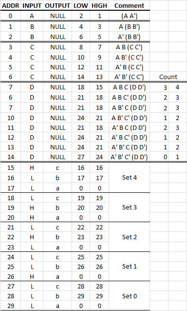
I looked at using an incrementer. It can be done in hardware or in software. Two options in software (1) finite state machine or (2) using memory bits. Here is a memory bit version:
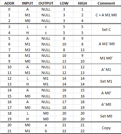
Here are the equations (from Logic Friday):
c = A m1 m0;
s1 = A m1' m0 + m1 m0' + A' m1 ;
s0 = A m0' + A' m0;
So now I can count up to seven switches at a cost of 22 instructions per switch. An improvement on the 5 switch FSM version but not the 4 switch FSM version.
A Binary Tree Version
I reworked the five switch version using a binary decision tree:
A big improvement at 49 instructions.
A Memory Bit Version
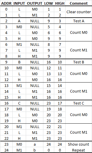
Using two memory bits and three switches (now 25 instructions):
An finally a four switch binary tree version (30 instructions):
So although a truth table and logic minimisation will get you a solution that is easy to implement, hand crafted code will win if you put the time in.
Conclusion
Without memory or registers, the unavailability of subroutines and variables severely limits programming options. Coding density is also very low. If the problem can be modelled with truth table, a finite state machine, a programmable logic array or a decision tree then it may work well.
Adding memory and other hardware to improve the performance of a one bit CPU would make them of similar complexity of a four bit CPU. This limits the appeal of this approach.
The MC14500B with its ALU will have higher code density but will still suffers the same limitations as my ALU-less version.
Programming the One Bit CPU using logic equations is surprisingly easy. Here are the 2 bit adder logic equations:
- c = A m1 m0;
- s1 = A m1' m0 + m1 m0' + A' m1 ;
- s0 = A m0' + A' m0;
And the program code development steps:
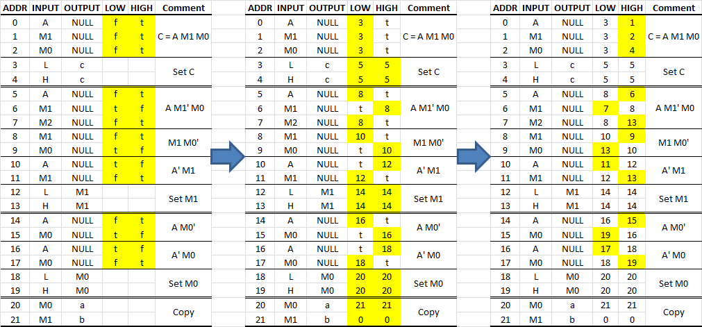
The steps are:
- First create a truth table.
- Solve the logic equations (using Logic Friday).
- Populate the comments with the equations to model.
- Populated the true/false conditions with "t" of "f" (hi-lighted yellow in the first table above).
- Set the jump address for the false conditions which is usually the next logic equation block (hi-lighted yellow in the second table above).
- Set the next address for the true conditions (hi-lighted yellow in the third table above).
- Most of the code outputs to "NULL".
Regards AlanX
Discussions
Become a Hackaday.io Member
Create an account to leave a comment. Already have an account? Log In.