 agp.cooper
Flash Programmer
I need a programmer for the FLASH ROM. I designed something in EasyEDA (a PCB fabrication service) but decided strip-board is more appropriate:
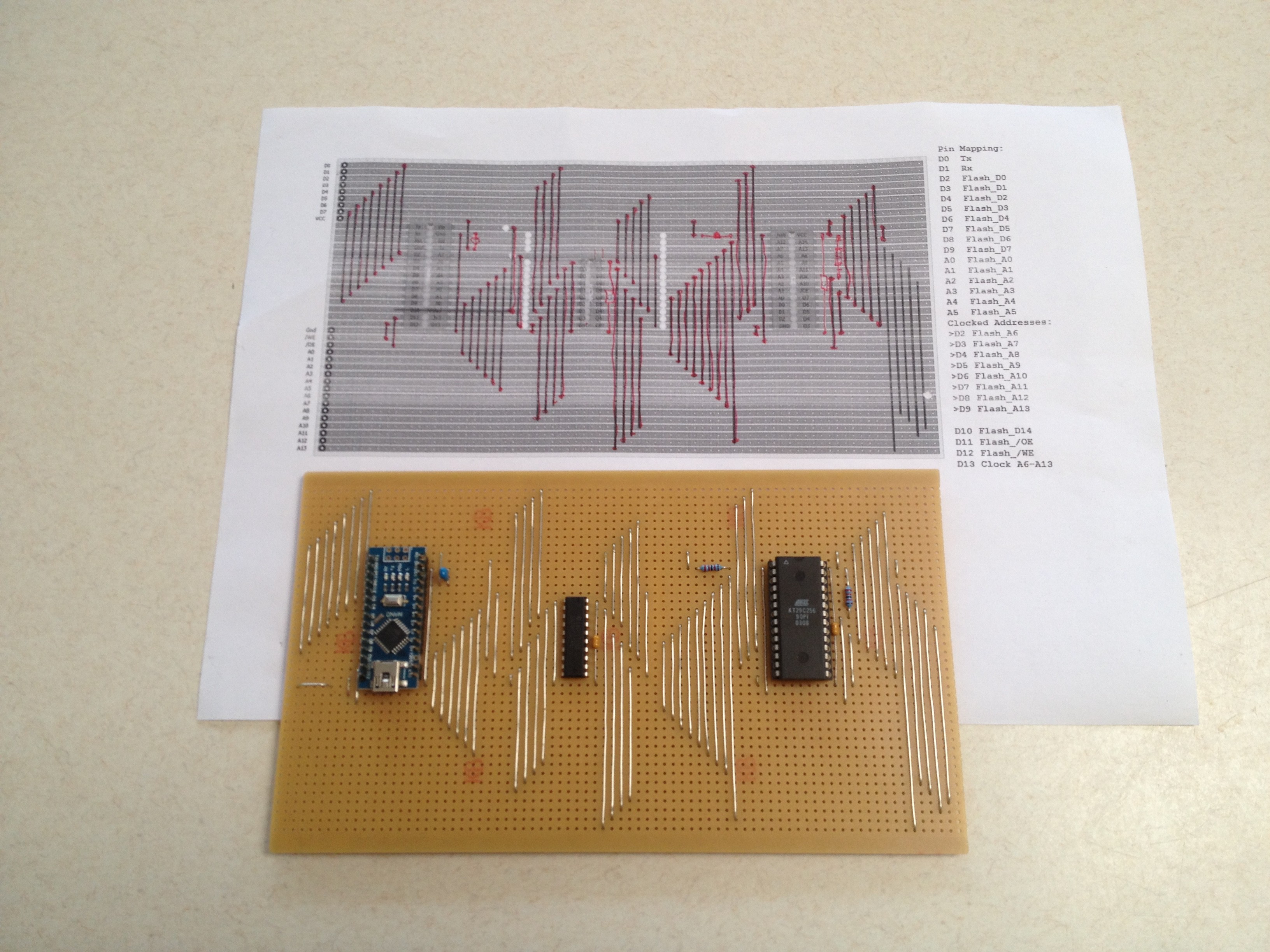
I destroyed a RAM chip before due to careless programming (... is there really any other type?), so I added 1k resistors between the Nano databus and the Flash data bus (not shown above). The strip-board has pretty high capacitance which slows down the access time down to about 1 us! Anyway I can read the chip (pretty sure I am reading the chip), and the address latch is working, but I can't get it to write. It's just a matter of time working out why it it not working.
Its a New Day
This morning I popped the Flash chip and configured the Nano to count, databus and then address bus with and without !WE. The maximum frequency was 178kHz. All the data lines and address lines had the correct frequency. The only problem I found is that 1us (program) delay was about 120ns!
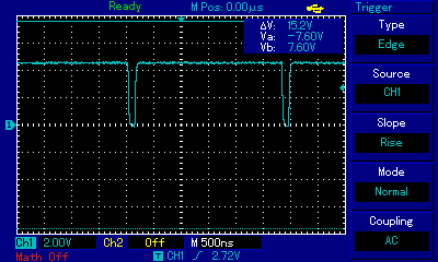
Using "delayMicroseconds(2);" gives me about 1us:
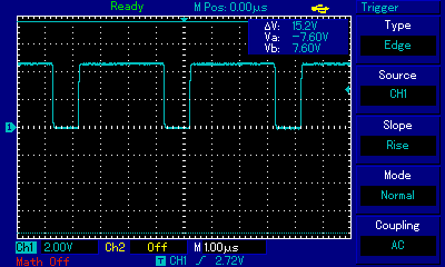
As I added 1k resistor to the databus to protect against bus conflict (or bad programming), I expected the bus to slowdown. Here is is on the Arduino side:
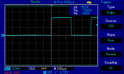
And on the Flash side (with the chip re-installed):
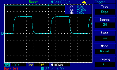
Thus the need for the 1us wait for the databus.
Remember that it is only the programmer that has the protective resistors so the slow down is not material.
The supply voltage is about 4.7v which is good enough, so I conclude the board is functional, back to codding errors.
Polling
The AT29C256 allows polling during the write cycle. It returns the complement of the last byte written. The table below shows the byte written|Read:
0000: 00|FF 01|BF 02|FF 03|BF
0004: 04|FF 05|BF 06|FF 07|BF
0008: 08|FF 09|BF 0A|FF 0B|BF
000C: 0C|FF 0D|BF 0E|FF 0F|BF
0010: F0|7F F1|3F F2|7F F3|3F
0014: F4|7F F5|3F F6|7F F7|3F
0018: F8|7F F9|3F FA|7F FB|3F
001C: FC|7F FD|3F FE|7F FF|3F
0020: 00|FF 01|BF 20|FF 30|BF
0024: 40|FF 50|BF 60|FF 70|BF
0028: 80|7F 90|3F A0|7F B0|3F
002C: C0|7F D0|3F E0|7F F0|3F
0030: 0F|FF 1F|BF 2F|FF 3F|BF
0034: 4F|FF 5F|BF 6F|FF 7F|BF
0038: 8F|7F 9F|3F AF|7F BF|3F
003C: CF|7F DF|3F EF|7F FF|3F
Its garbage! "FF" should return "00" not "3F".
Okay swap out the chip (it was a bit suspect as it has scratches on it - is it new?).
WTF! It works, this is the second run where I over wrote my first success:
Welcome to the AT19C256 FLASH Programmer V1.0
First read the FLASH (y/n)?
0000: 00 01 02 03
0004: 04 05 06 07
0008: 08 09 0A 0B
000C: 0C 0D 0E 0F
0010: F0 F1 F2 F3
0014: F4 F5 F6 F7
0018: F8 F9 FA FB
001C: FC FD FE FF
0020: 00 01 20 30
0024: 40 50 60 70
0028: 80 90 A0 B0
002C: C0 D0 E0 F0
0030: 0F 1F 2F 3F
0034: 4F 5F 6F 7F
0038: 8F 9F AF BF
003C: CF DF EF FF
FLASH read done.
Write the FLASH (y/n)?
FLASH write done.
Verify (read) the FLASH (y/n)?
0000: 00|00 00|00 00|00 00|00
0004: FF|FF FF|FF FF|FF FF|FF
0008: 00|00 00|00 00|00 00|00
000C: FF|FF FF|FF FF|FF FF|FF
0010: 00|00 00|00 00|00 00|00
0014: FF|FF FF|FF FF|FF FF|FF
0018: 00|00 00|00 00|00 00|00
001C: FF|FF FF|FF FF|FF FF|FF
0020: 00|00 00|00 00|00 00|00
0024: FF|FF FF|FF FF|FF FF|FF
0028: 00|00 00|00 00|00 00|00
002C: FF|FF FF|FF FF|FF FF|FF
0030: 00|00 00|00 00|00 00|00
0034: FF|FF FF|FF FF|FF FF|FF
0038: 00|00 00|00 00|00 00|00
003C: FF|FF FF|FF FF|FF FF|FF
FLASH verify done.
FLASH Programmer done.
I am a happy little flash programmer now.
AlanX
Discussions
Become a Hackaday.io Member
Create an account to leave a comment. Already have an account? Log In.