 Sepio
SepioAfter printing all the parts for AXIS 1 it was time to put it all together.
First I had to glue some parts together. I used the screws to align the parts.
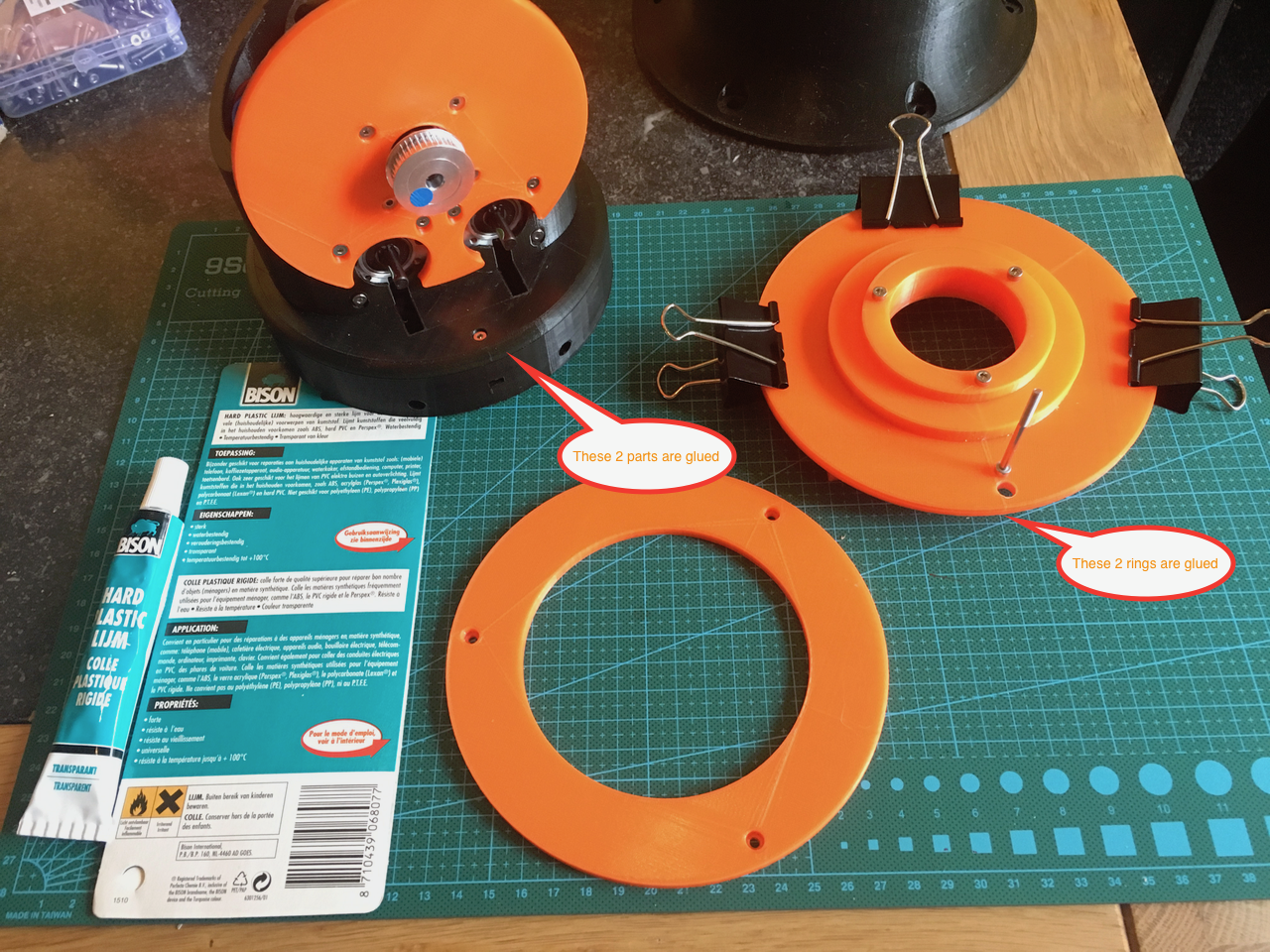
I added a hole in the orange ring. I used the bearing cover ring for positioning the hole.
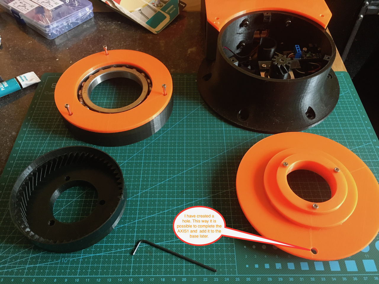
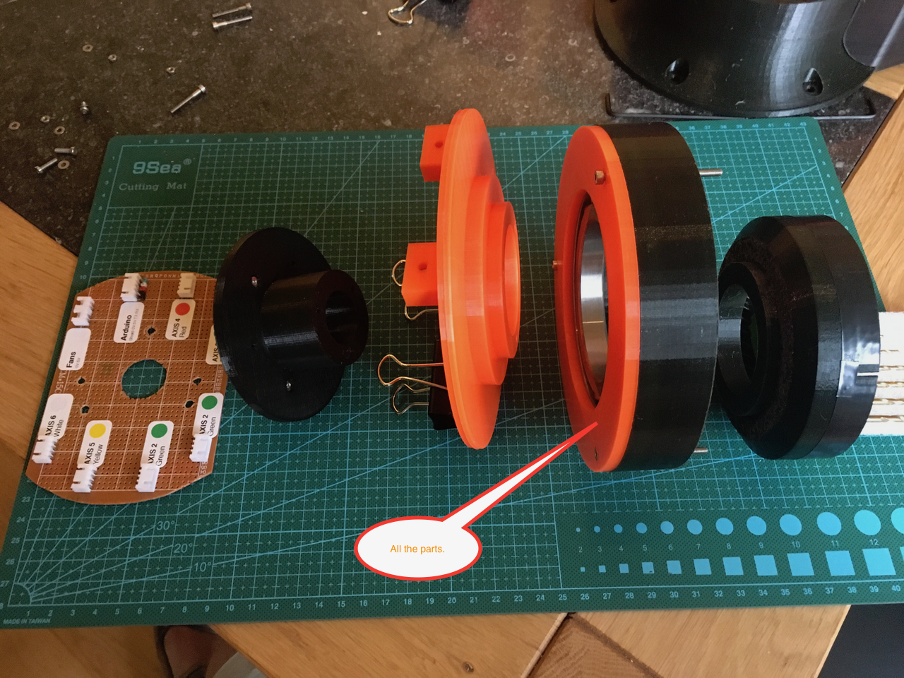
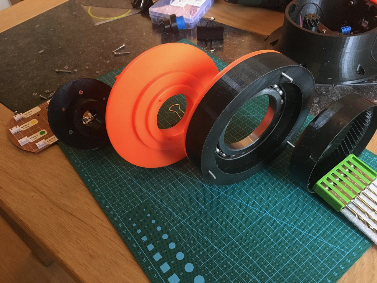
All the parts that will be mounted together. I added a few drops of glue between the black and orange bearing ring. This way the ring can't the screws holes are aligned and it will be easier to mount AXIS1 to the base. I also added some ball bearing.
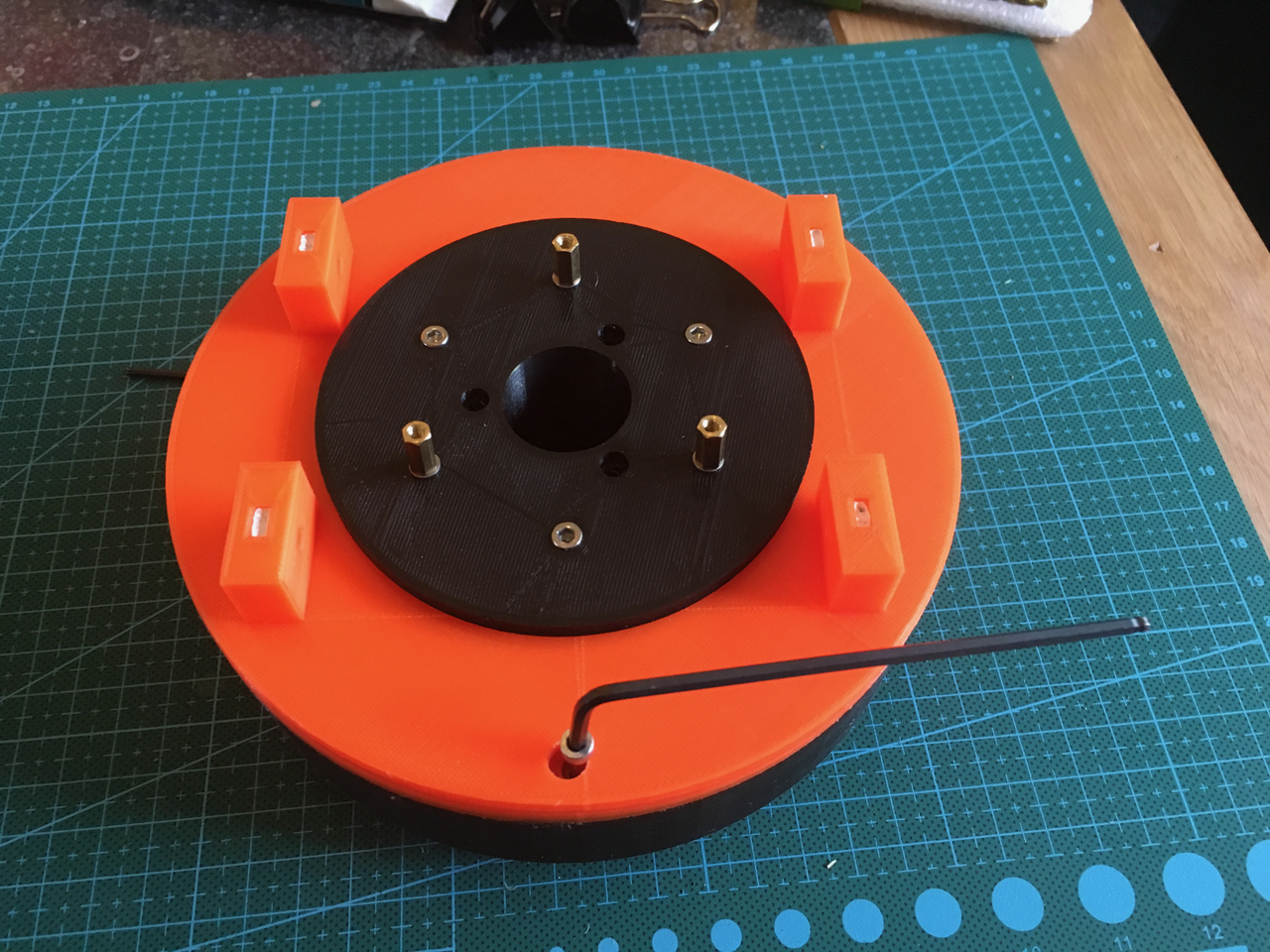
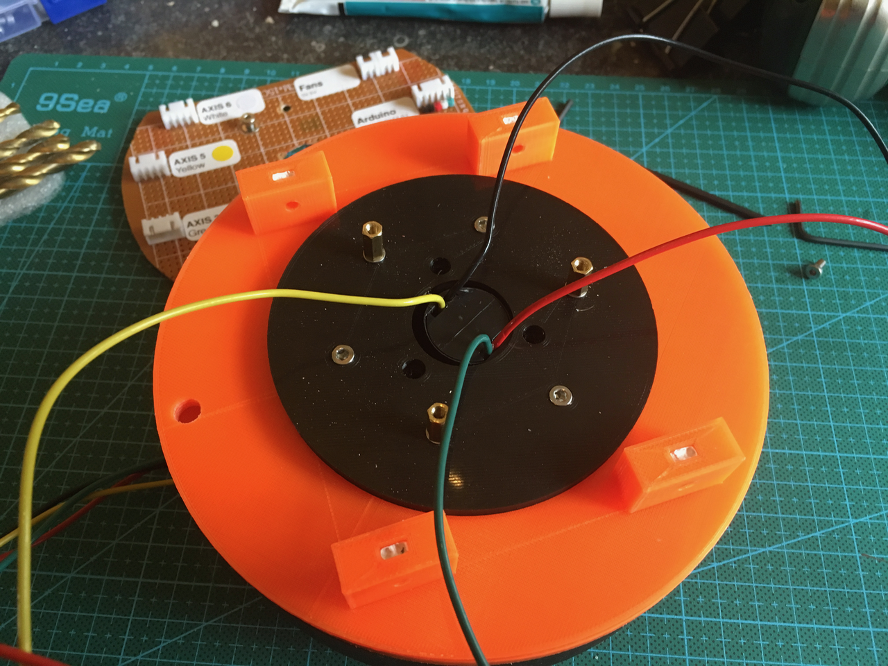
Axis 1 from the top side. (I changed the screw and nuts to mount the PCB to PCB standoff pillars).
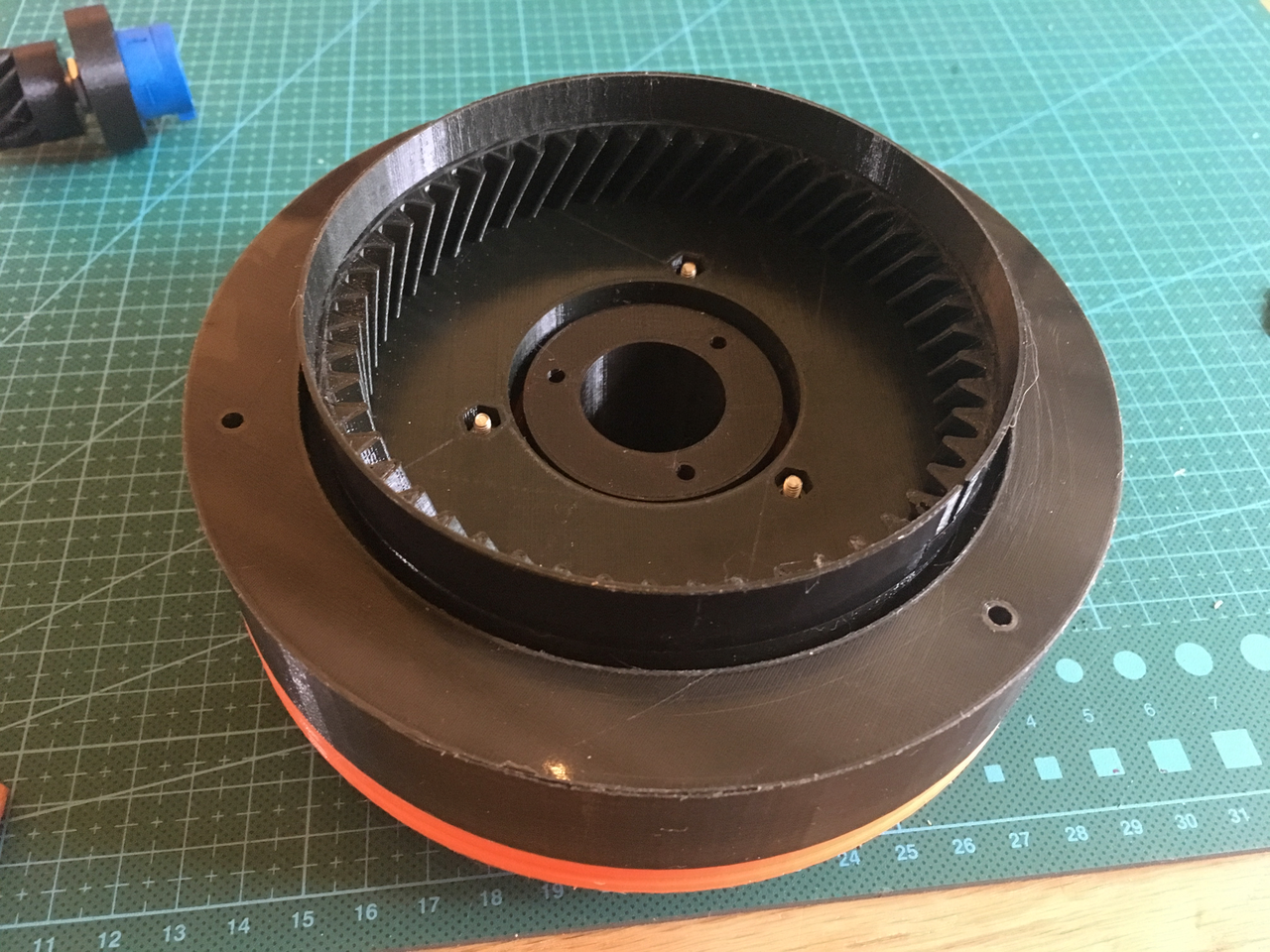
And from the bottom side. De inner black tube is used to mount the slip ring.
An example of the slip ring (this one doesn't have enough wires).
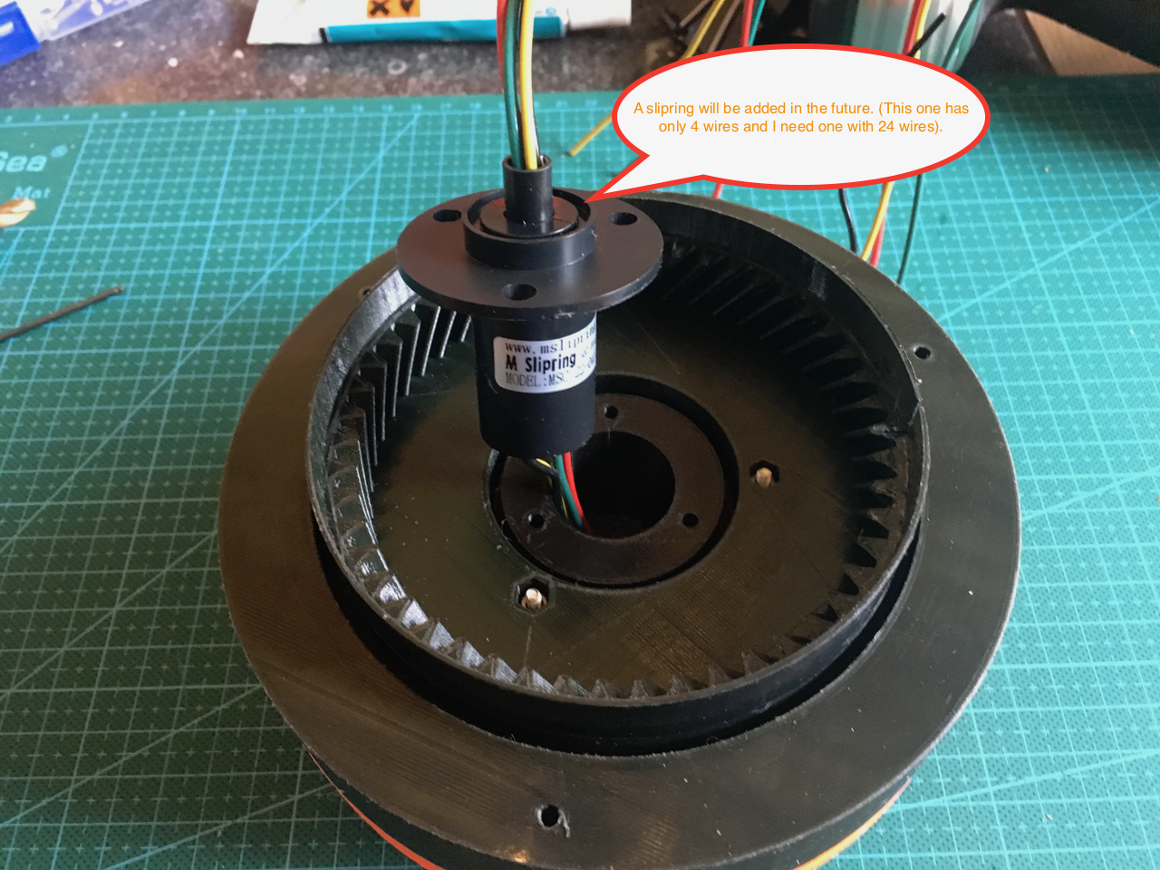
If the slip ring is inserted it will look like this. The part with the wires can rotate. The little gap on the top right side of the gear is used for the optical gate sensor.
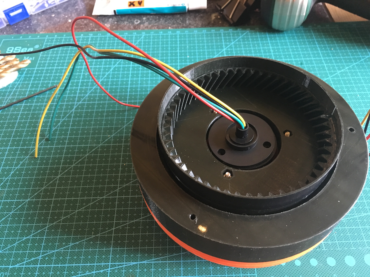
The same slip ring from the top.
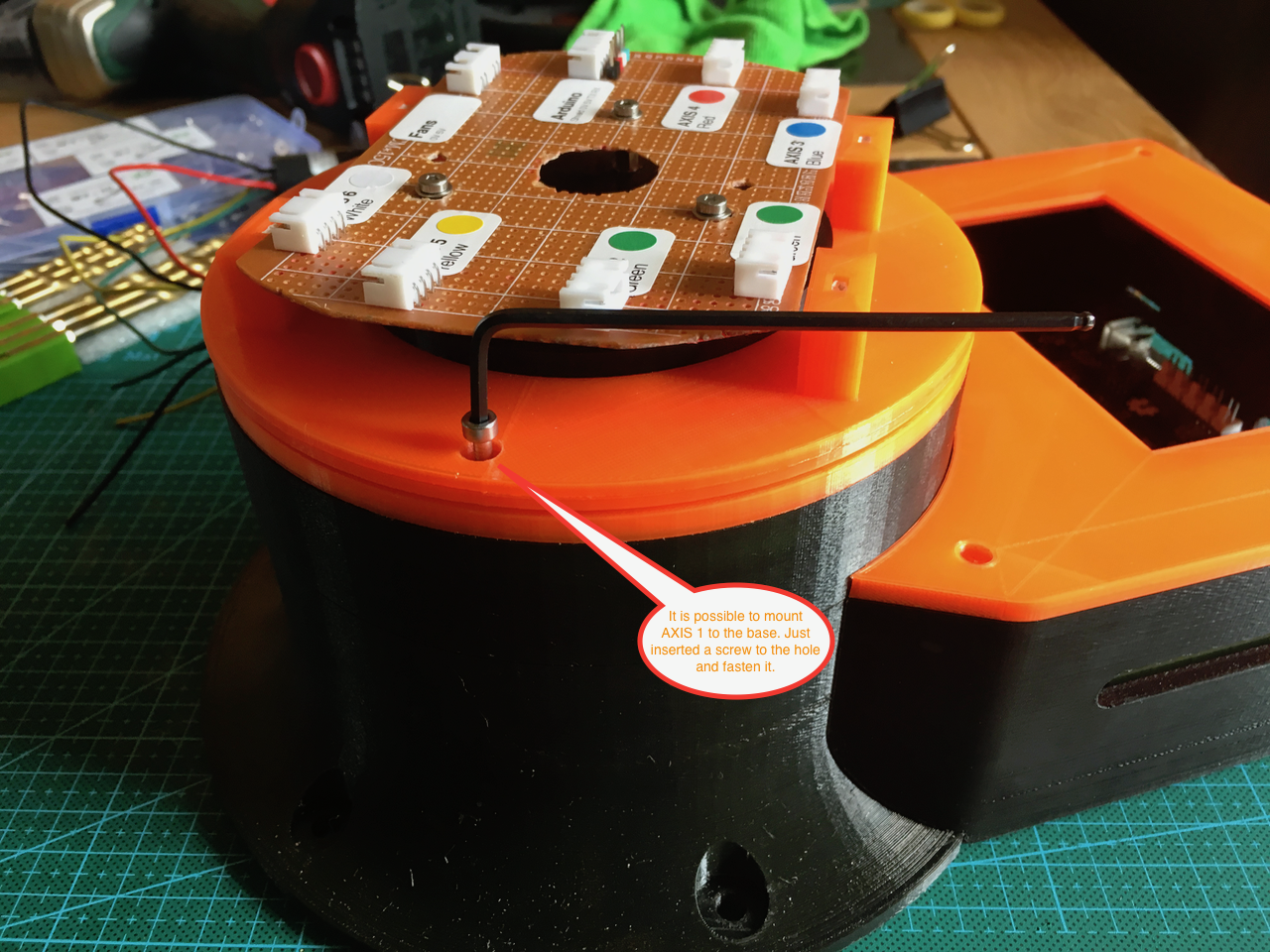
After mounting the PCB it was time to put AXIS 1 on the base. The little hole in the top ring can now be used to insert and fasten the screws.
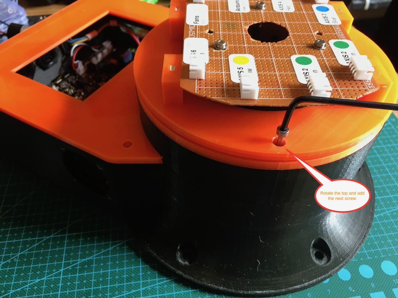
Just rotate the top ring 120 degrees and insert the next screw.
I didn't add the 10 turn potentiometer in the base yet. Because I still have to create the correct firmware It can now rotate continuously.If I add the potentiometer it is limited to one rotation. One rotation of AXIS 1 is about 8 turns of the potentiometer. Without support for this in the firmware it could (and would) break something.
Now it was time to turn the power on and it worked perfectly.
Discussions
Become a Hackaday.io Member
Create an account to leave a comment. Already have an account? Log In.