 Sepio
SepioLast week many parts arrived from China. One of them was the slip ring. Also Danny added the base with the fan holes for a 40x40X10 mm fan.
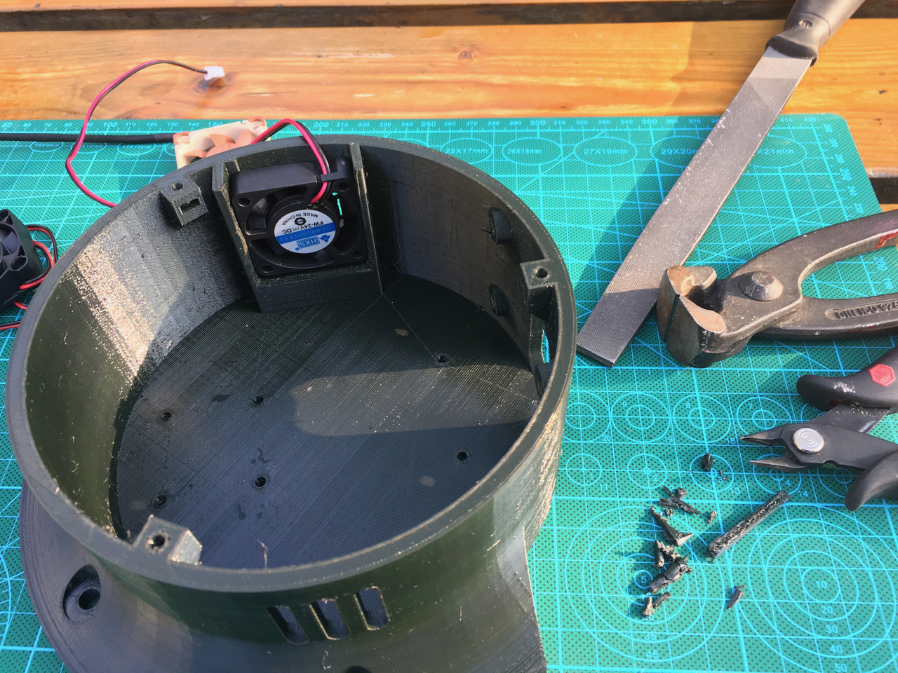
After printing the new base I tried to add the fan. But it didn't fit. All the 40x40x10 mm fans are 10.8 mm high. Why don't they call it a 40x40x11 mm fan.
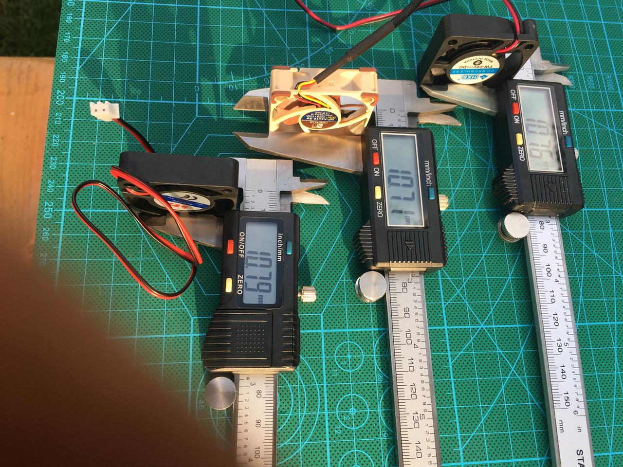
The base only accepts 9,8 mm fans.

So I had to use some pliers to break some plastic away. I used hot glue to mount the fan.
Now it was time to mount the slip ring. The slip ring has 24 wires. I created 5 groups of 4 wires (green, blue, orange, red and white for the stepper motors and a group of 2 wires for the power lines (black) and a group of 2 for the serial communication (orange). I wanted this wires to be shielded. The shield on the foto below is long enough to fit over the remaining wire. I used some copper tape to keep the shielding in place.
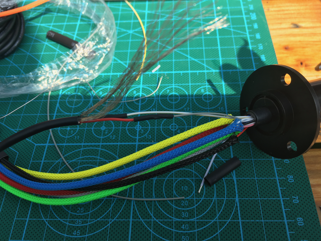
A piece of shrink wrap is used to fix the sleeves.
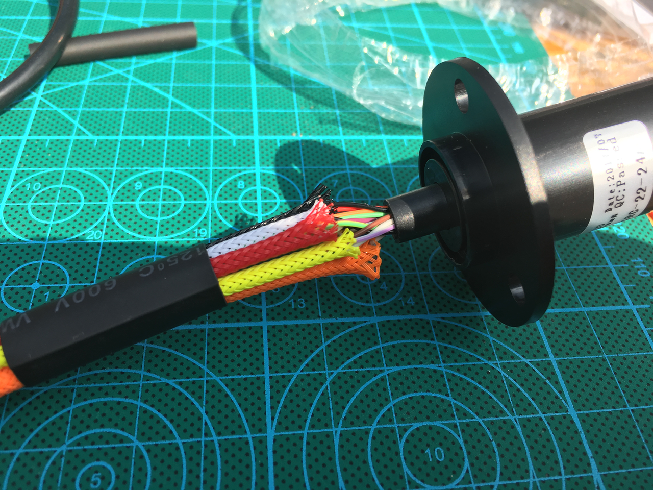
On the other end I used also some sleeving. The orange serial cable is longer because I want to be able to put the Nextion display on the table with all the wires attached.

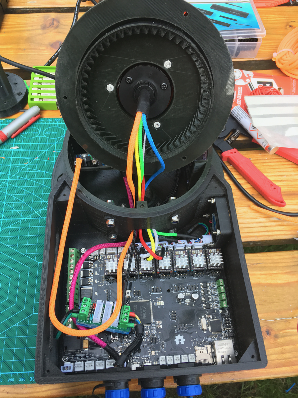
I used the old base (without the fan holes) so I could do the sleeving of the upper part. Also the bottom wires are fitted with connectors.

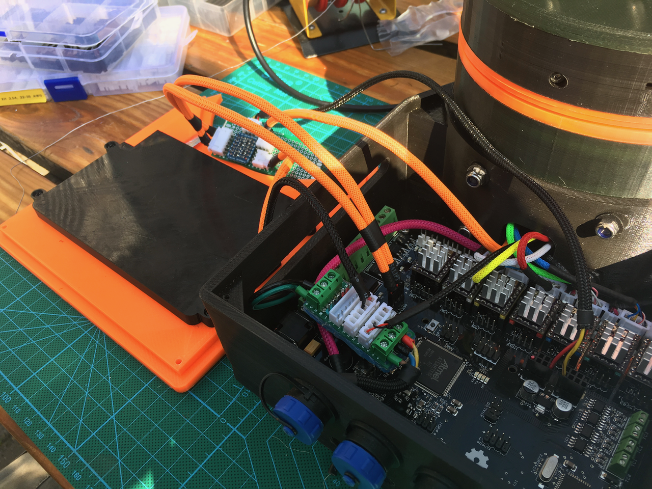
The top ones are fitted with connectors. I created a new PCB. All the stepper motor wires are on the left side. So there is room for step down convertor on the right side. I am going to use 24V power wires trough the slip ring. So I need a step down convertor above the slip ring to change it to 5V. This way I'am not restricted by the 2A max slip ring wires (24V x 2A = 48W, 5V * 2A = 10W). I think I need more then 10W for the arduino, sensors, led ring and servo.
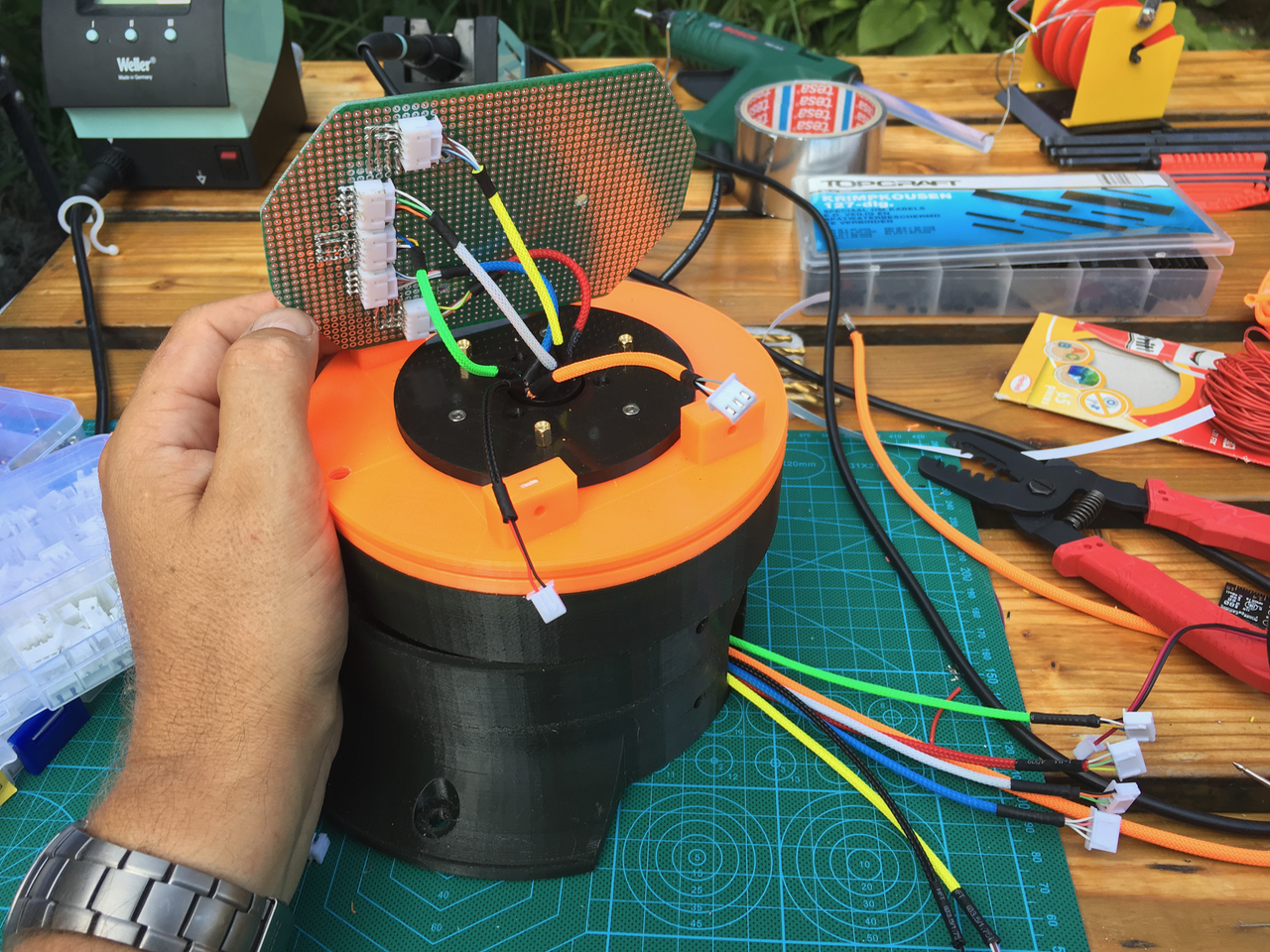
Now it was time to mount the art 2 part with al its wires on the base. The pink wire is used for the sensors. I made a small PCB (bottom left). (Green = 24V, Black = 0V, Red = 5V). This board is also used to power the Nextion and the 24V line though the slip ring.
The wires of the stepper motors are also sleeved and fitted with connectors. The connectors are arranged in such a way that the will fit in the gap.
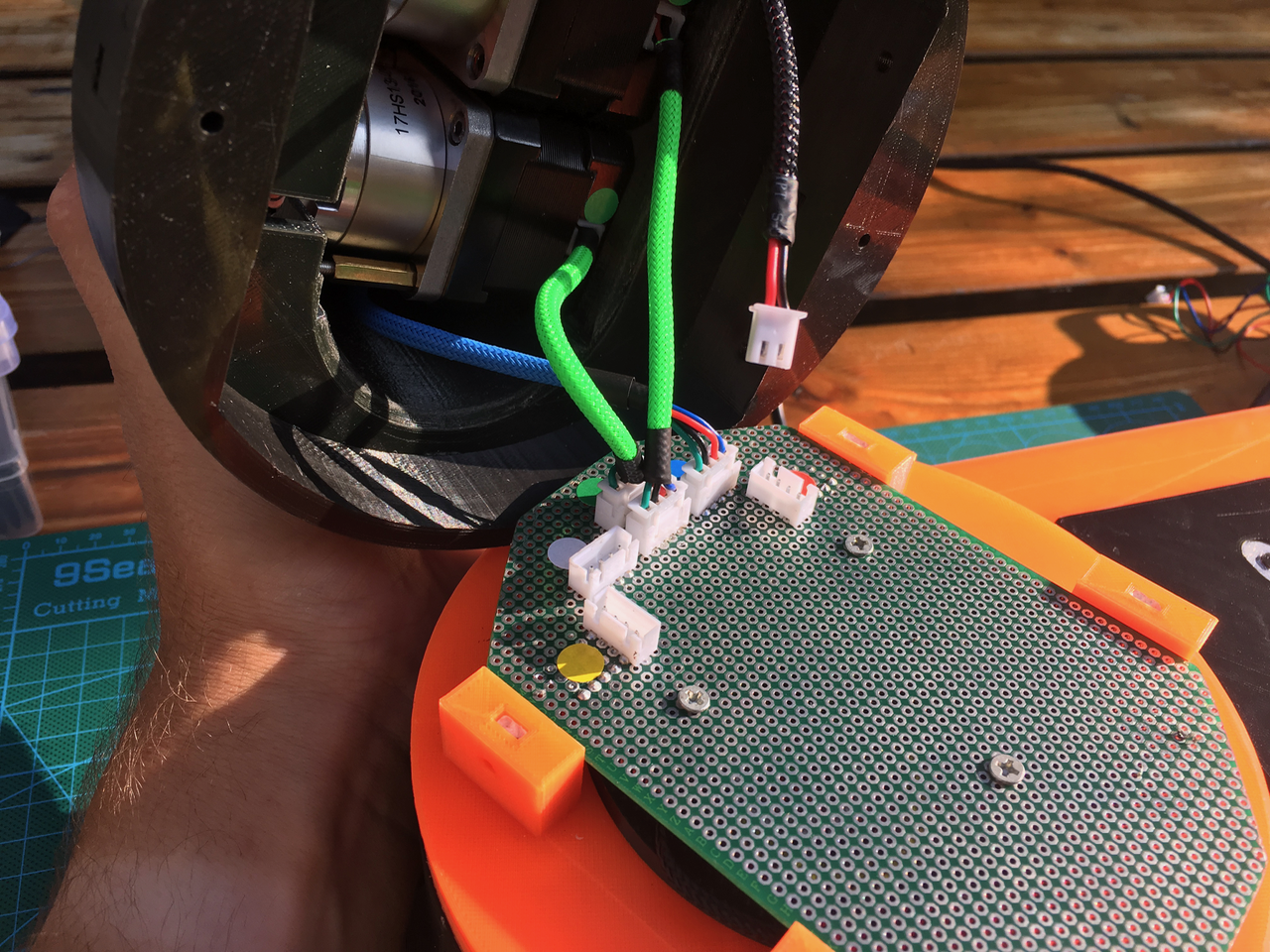
Everything fits.

I still had to connect the Nextion. I added some alu tape on the inside of the Nextion display cover as a shield. (Don't know if it will help).
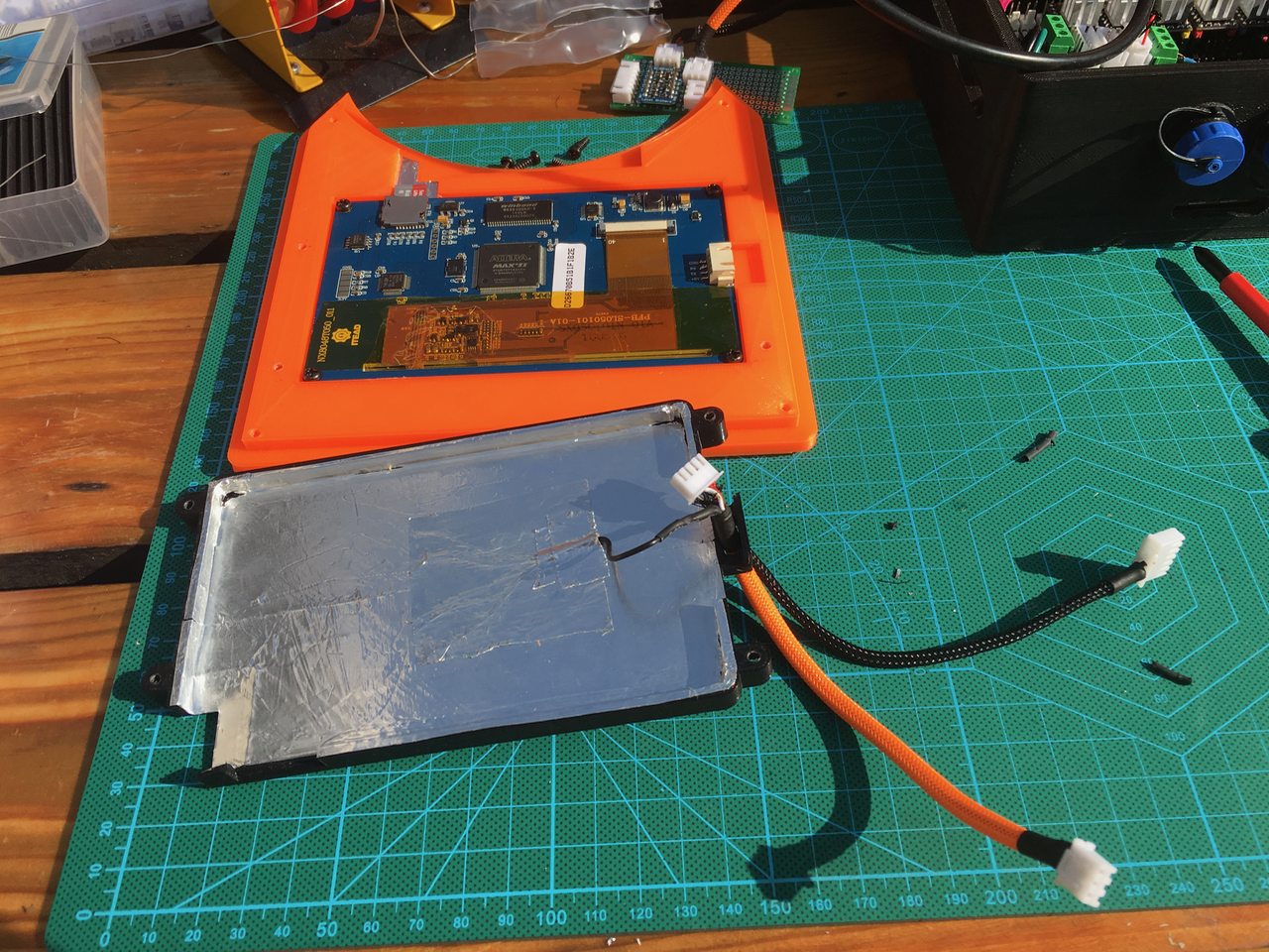
I created a small PCB (just above the Nextion display) with a power level convertor. The Ultratronics uses 3.3V and the Nextion and Arduino inside the arm are using 5V. The Nextion display is powered with the 5V from the power supply. The 24 line is used to power the top part of the arm. I want to add a Emergency button on the powersupply case which will cut the 24V line. This way the Nextion display can stay on.
Yes! It is still working :-)

Discussions
Become a Hackaday.io Member
Create an account to leave a comment. Already have an account? Log In.
If I see your work I wanted to start over with assembling my robotarm, I'm a little bit jealous 8-0
The result will be marvelous!
Are you sure? yes | no
Very astetic pleasing colors
Are you sure? yes | no
There are so many wires. This way it is easy to separate them. The sleeves don’t cost much. I used 2 mm and 4 mm sleeves. (2mm for the slip ring wires, 4 mm for the stepper motor, sensor and shielded cables). It also better for the airflow.
Are you sure? yes | no