 Sepio
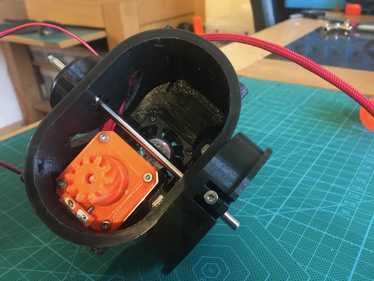
SepioI did a redesign of the Art 3 upper and lower body and the Art4 Axle. In Art 3 I added a fan and 2 bearings. I also changed the orientation of the mounting screws between the upper and lower body so It can be separated without removing the covers of Art 2.
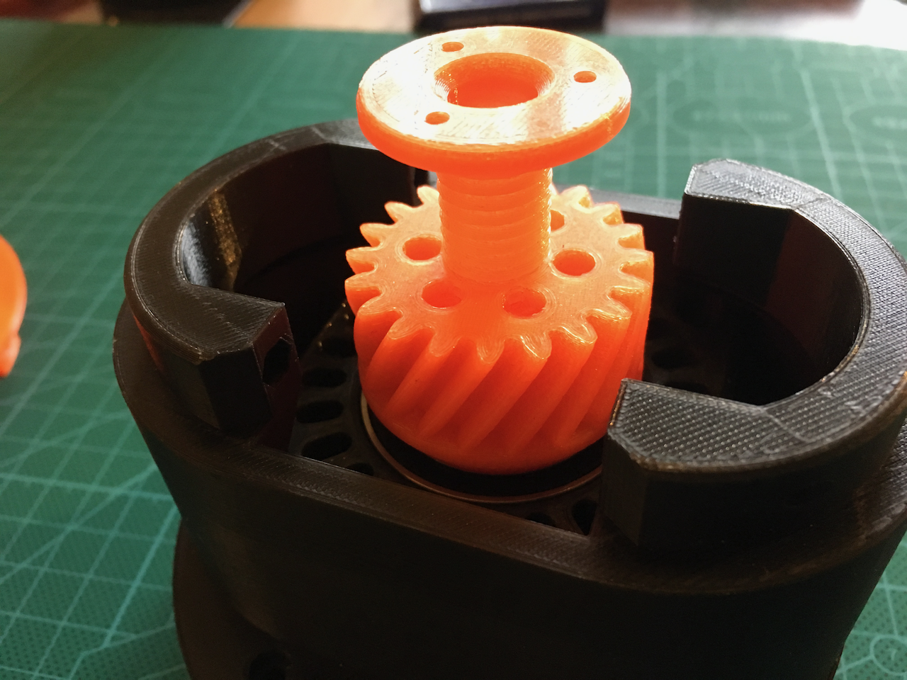
I changed the Art4 transmission Axle. The gearhead is a separate piece. The shaft itself is wide enough for another 24 wire slipring.
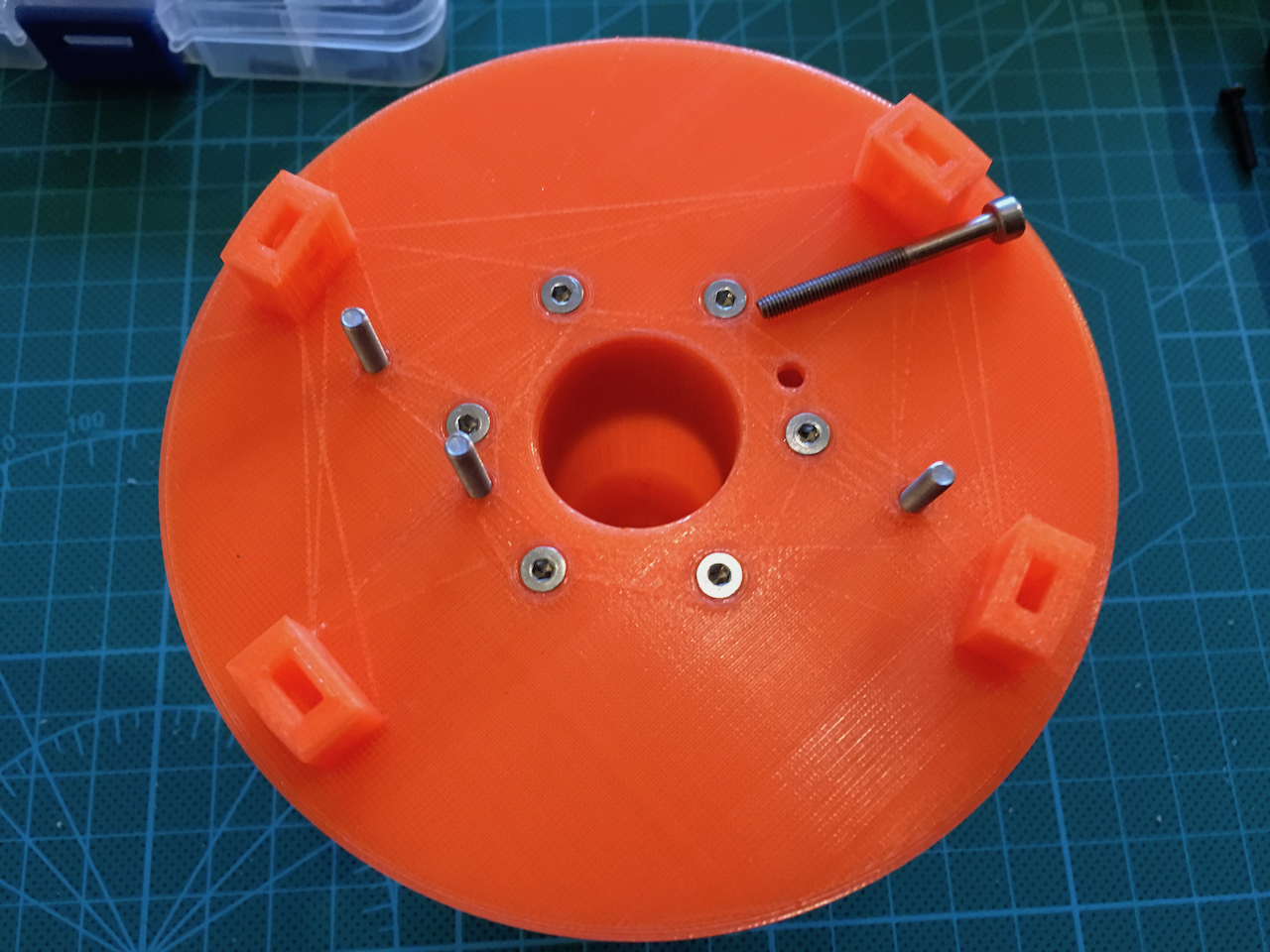
The Art 3 lower body. I moved the mounting points for the upper body to the upper body. Now it can be printed like below. I also moved the screw holes to the front and the back. It is now possible to leave this part connected to the lower base and add the upper body separately. There is also room for a 40x40 fan.
The fan intake. The fan is mounted on the inside.

The fan from the inside.
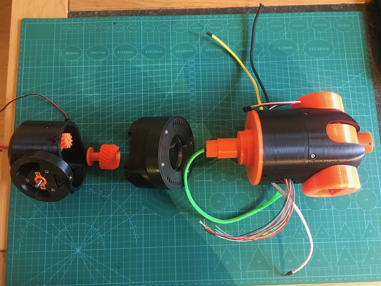
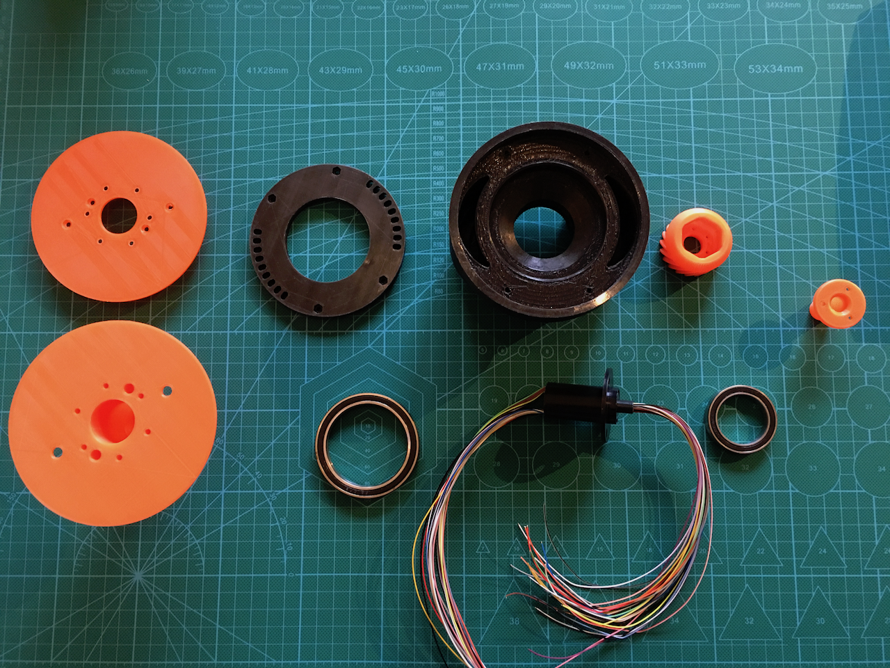
Below all the new/changed parts of the Art 3 upper body and the Art 4 shaft.
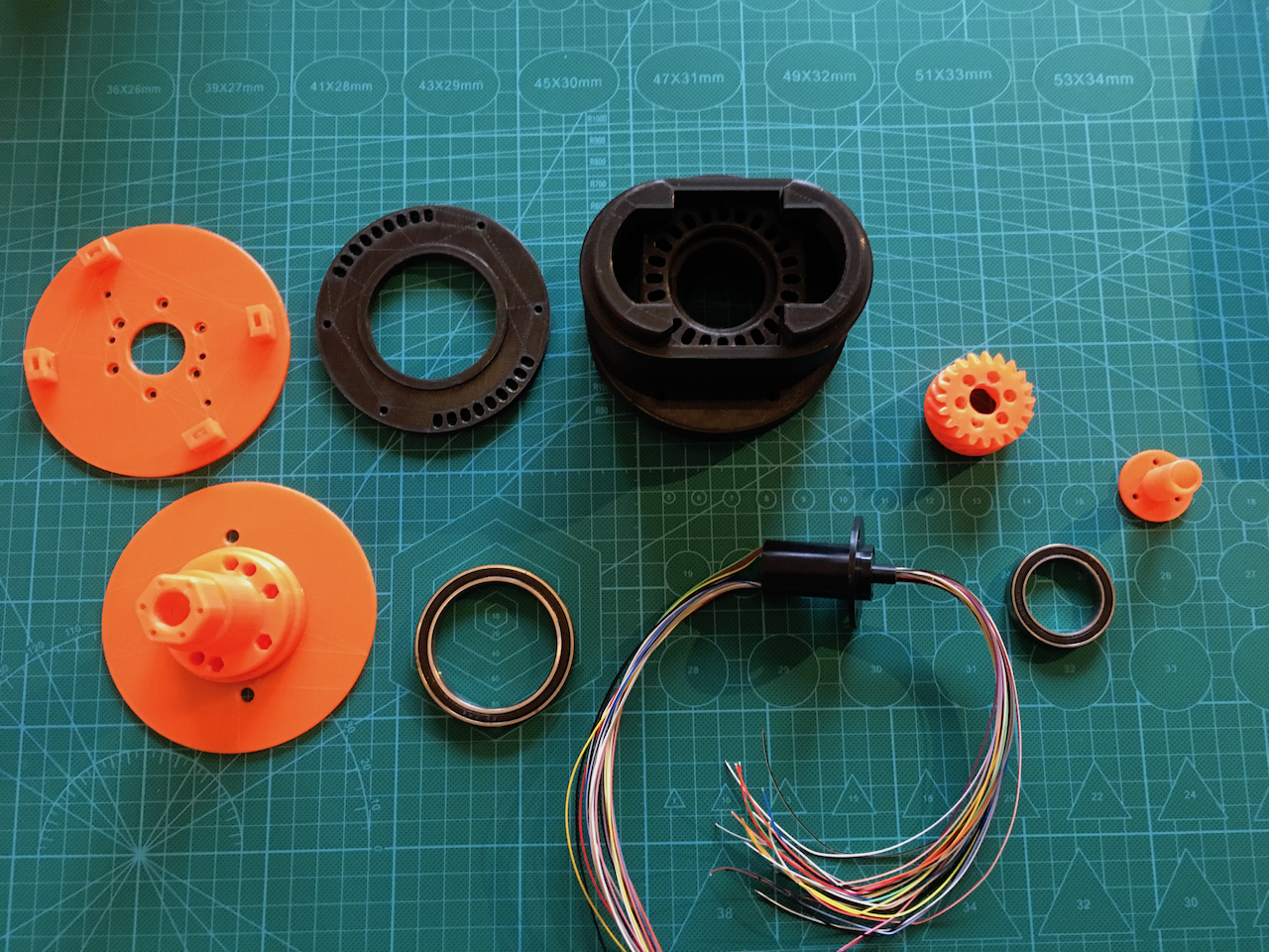
The left orange parts can be glued and screwed together. This makes printing easier.
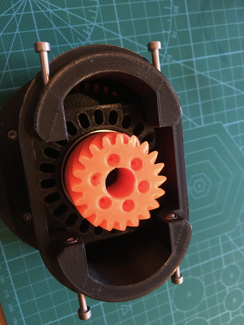
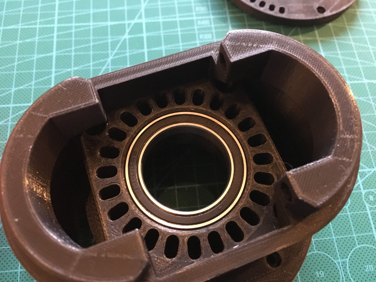
I used two bearings on the Art4 Axle.
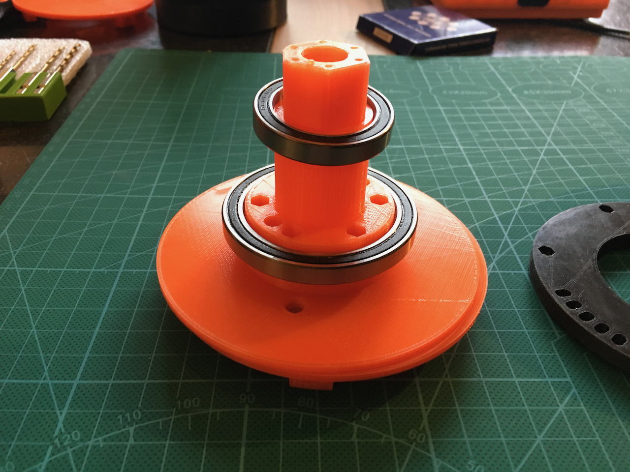
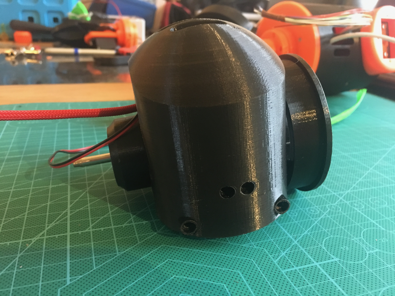
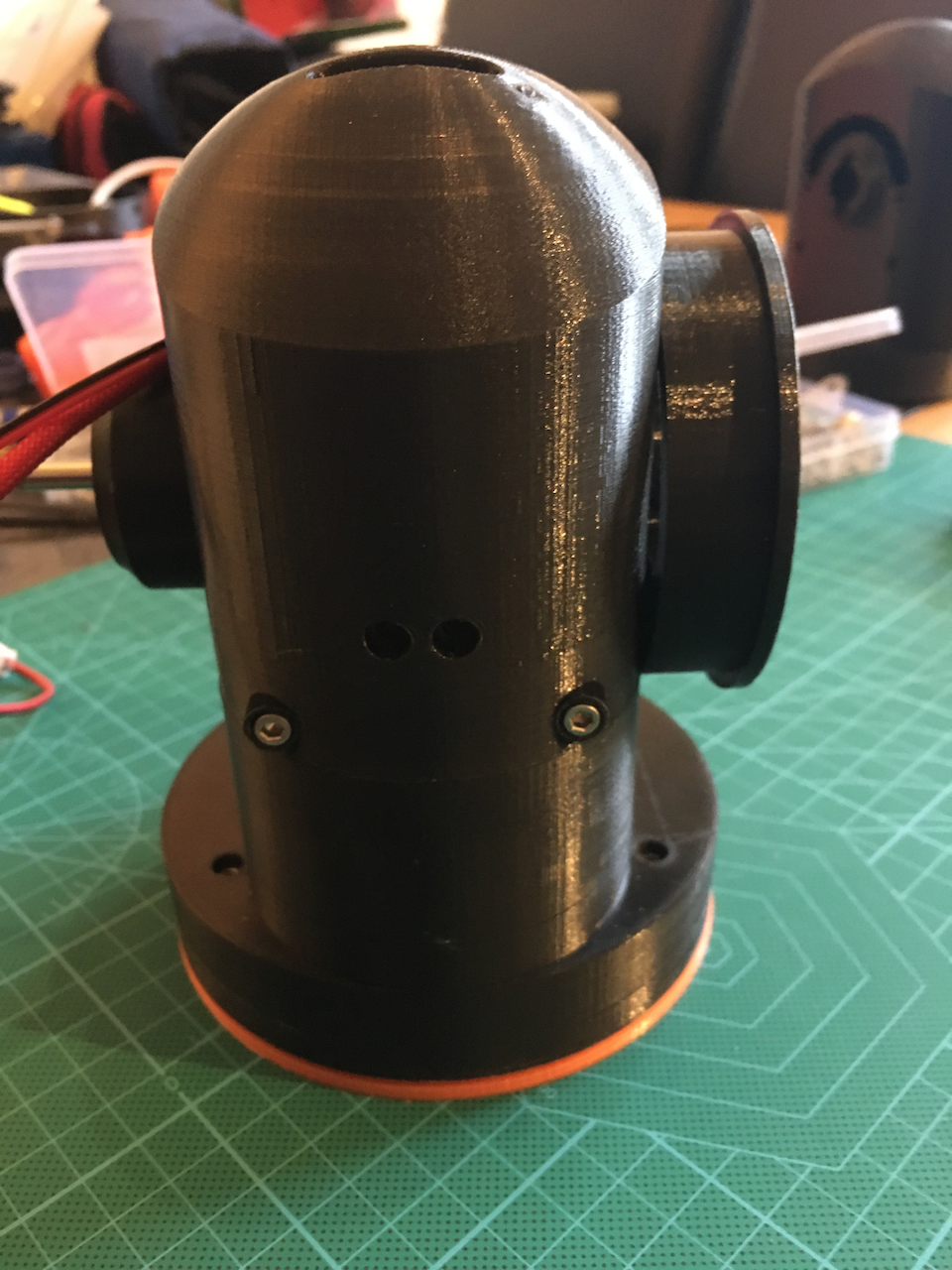
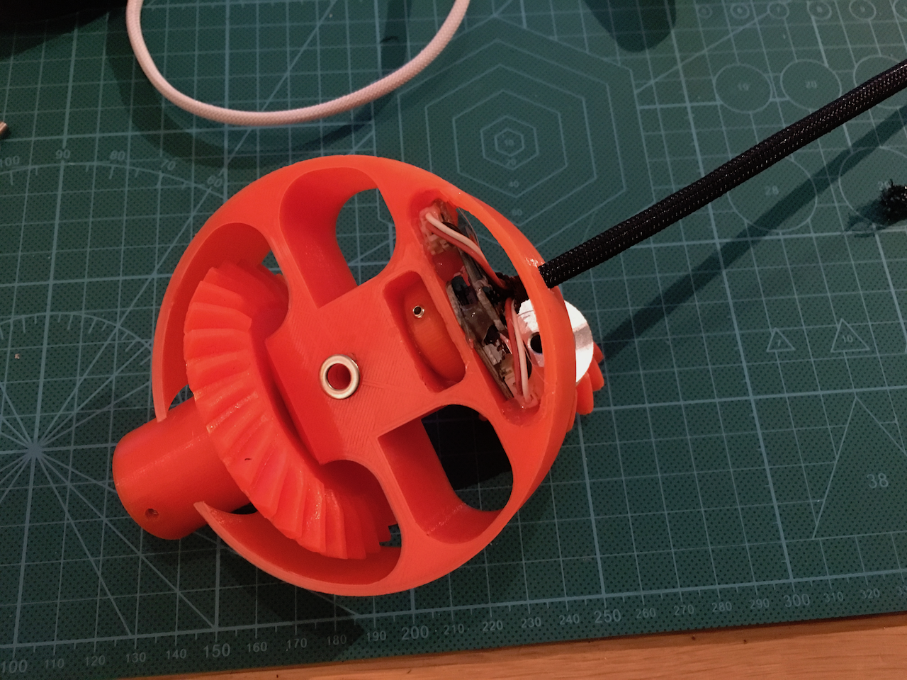
The upper bearing. (The extra holes around the bearing are just holes to save some plastic). The two holes on the side are for ventilation.
The lower bearing and the ventilation holes.
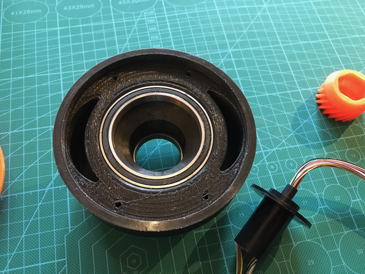
There is some room for the air to escape.

The bearing fix. The inner ring has to go on the inside and can be used to push the bearing on its place.
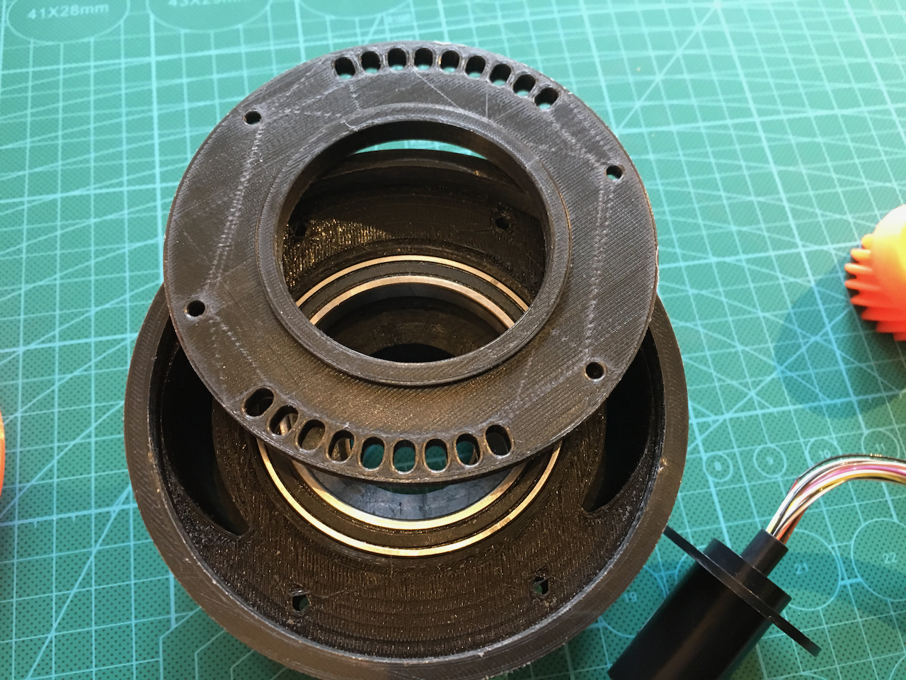
This way the bearing is fixed at its place,
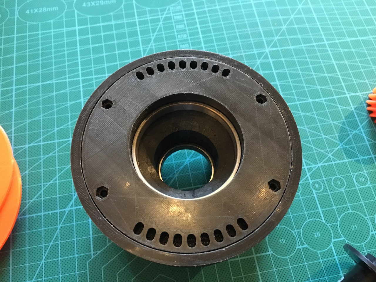
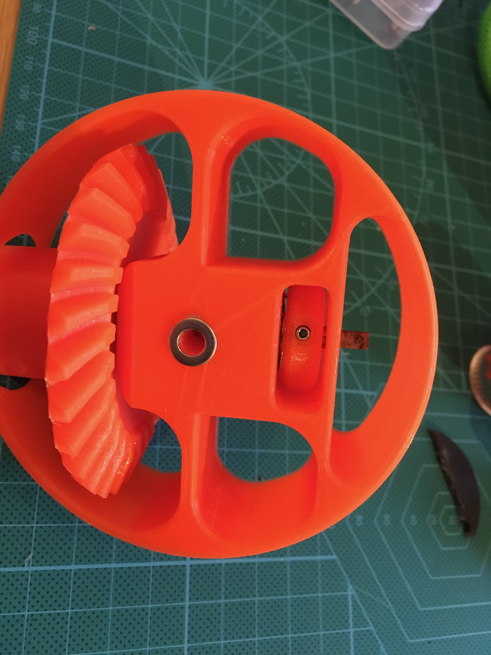
The extra holes are for setting the belt tension of the ART5 and 6 motors.
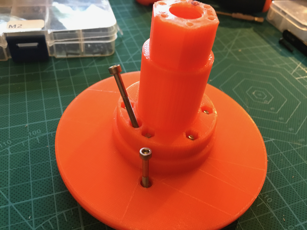
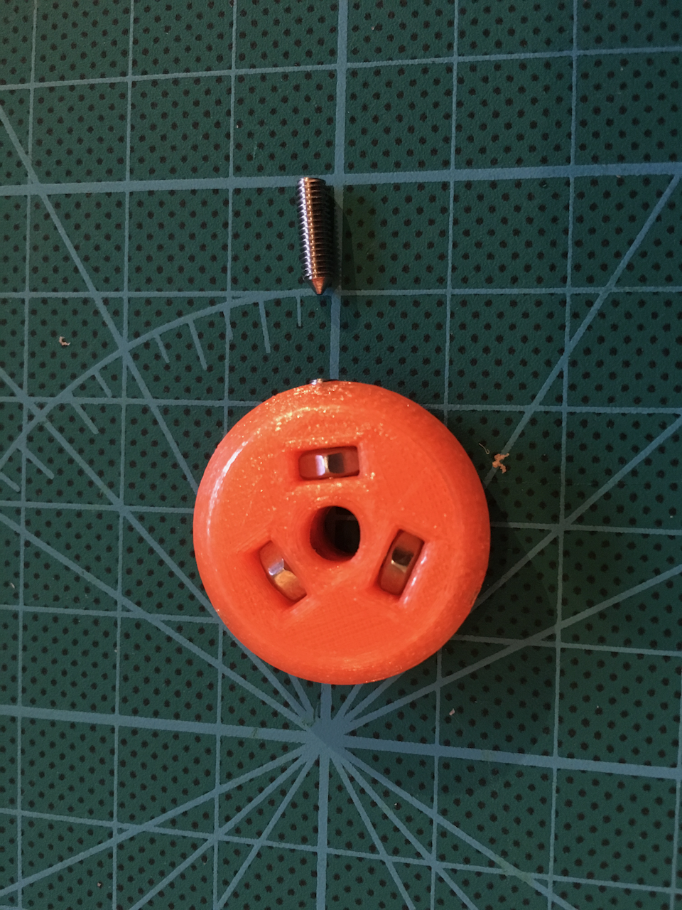
There is a small bump on the axle which can be aligned with the hole on the gear. This way the screw thread will work. (In a later stadium i used a knife to remove the bump. By rotating the gear 60 degrees it is possible to increase or decrease the length of the axle and the force on both bearings.

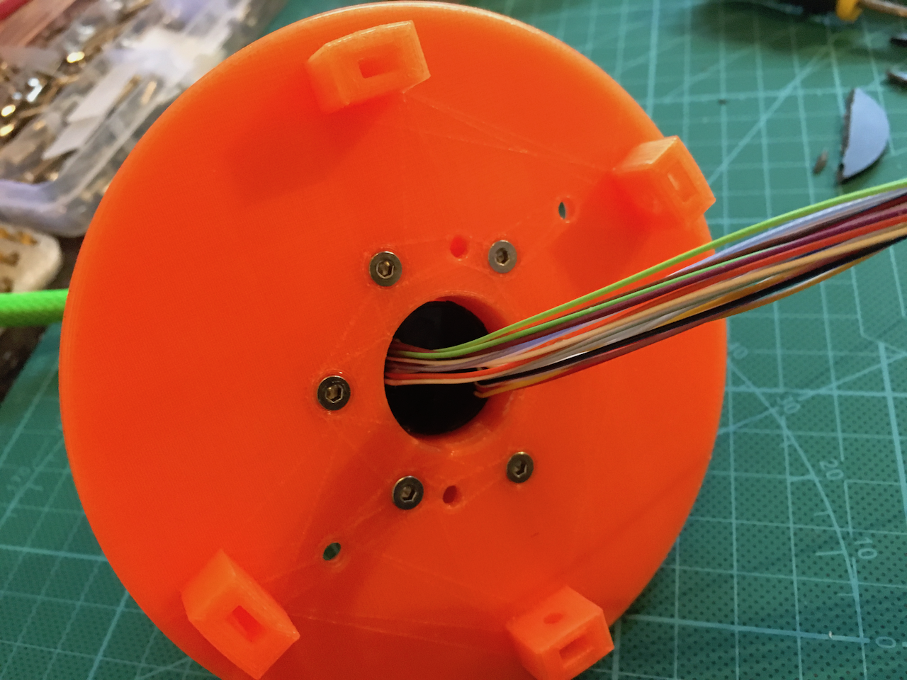
The gear-head can be screwed with 6 self taping screws on the shaft. A printed hollow screw adds some strength and can be used to hold everything at its place during the build.
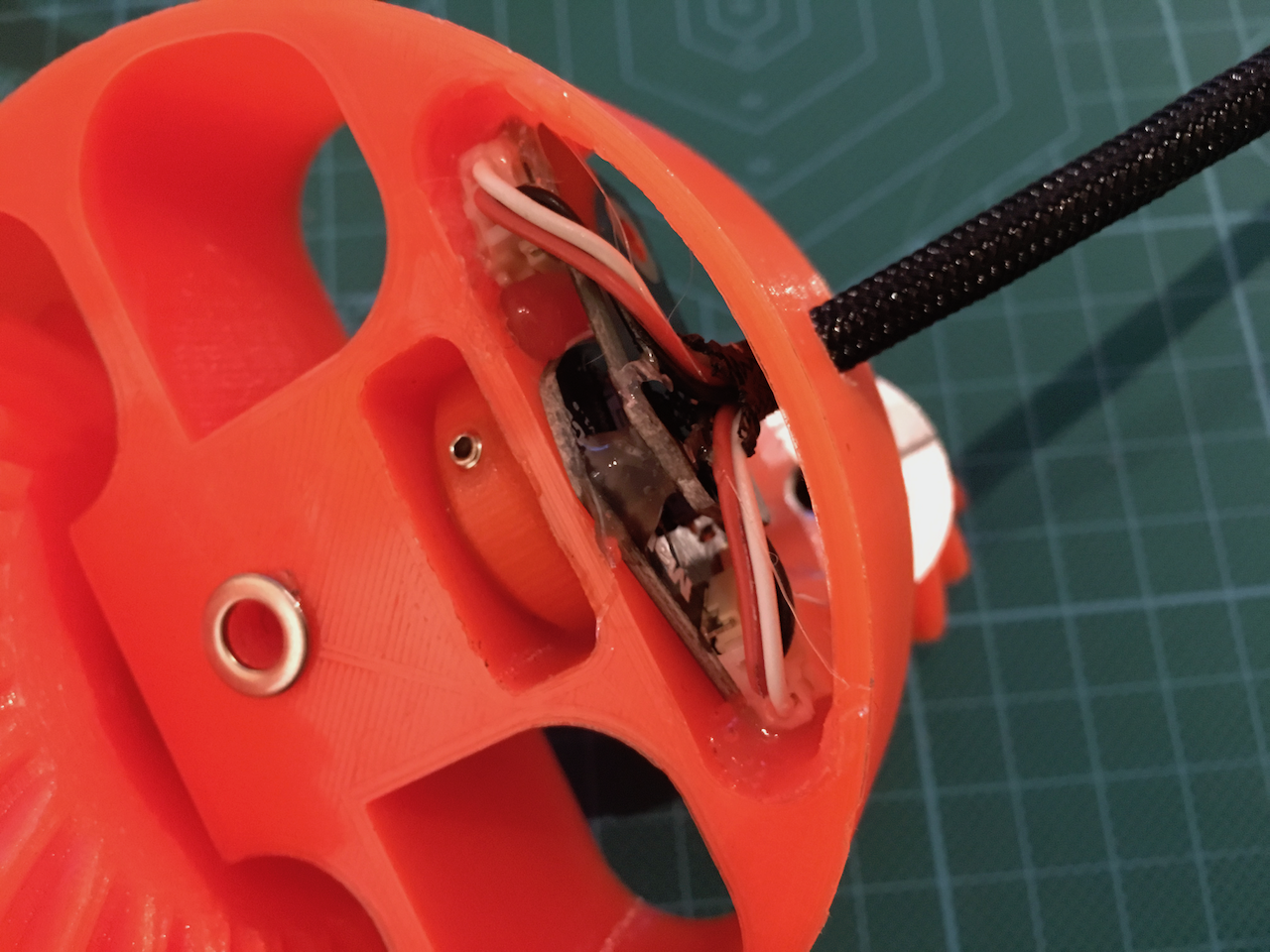
The outside ring of the slipring has to be removed.
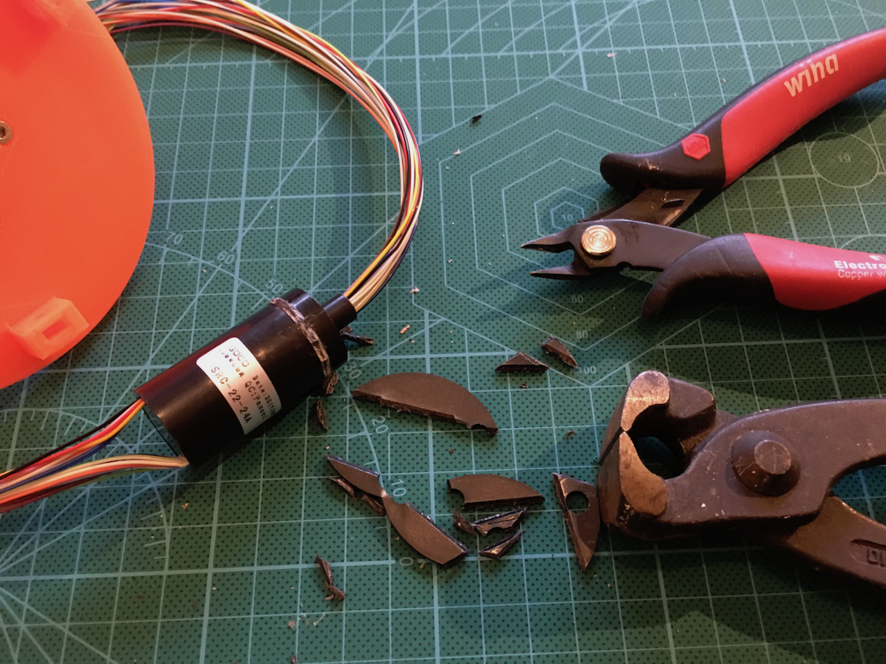
The outside is about 20mm. The hole inside the Axle is 22mm. Is used some foam tape and some electric tape to make the slipring a little bit thicker.
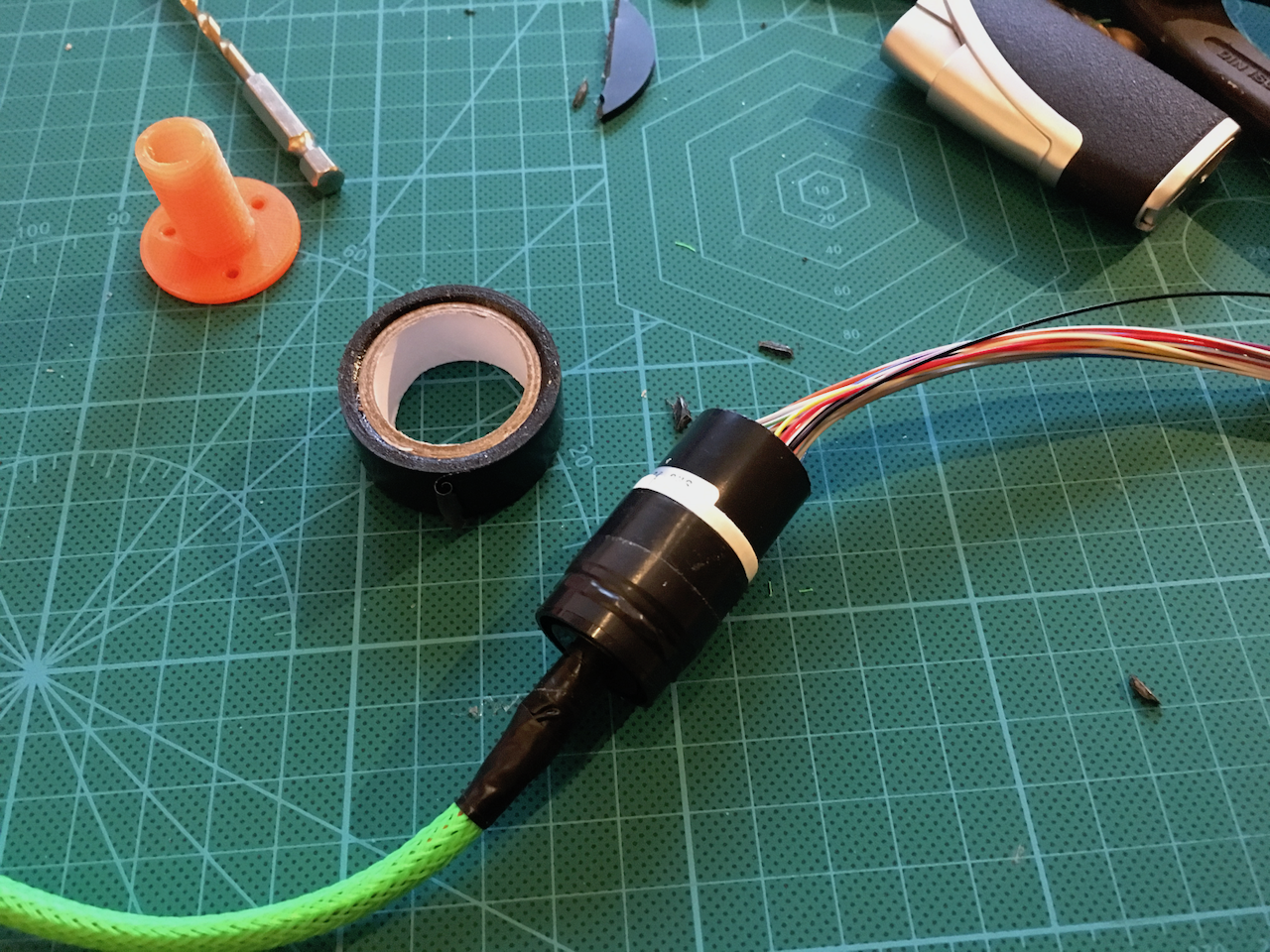
Now it can be pressed inside the base.
I also changed a few parts of Art 5 and 6. I added some holes for the nuts on the ring which fixes the Art 6 Axle. This way it can be tightened better.
The art 4 has changed slightly. There is a little bit extra room for the motors in the upper position. This makes adding the belts easier.
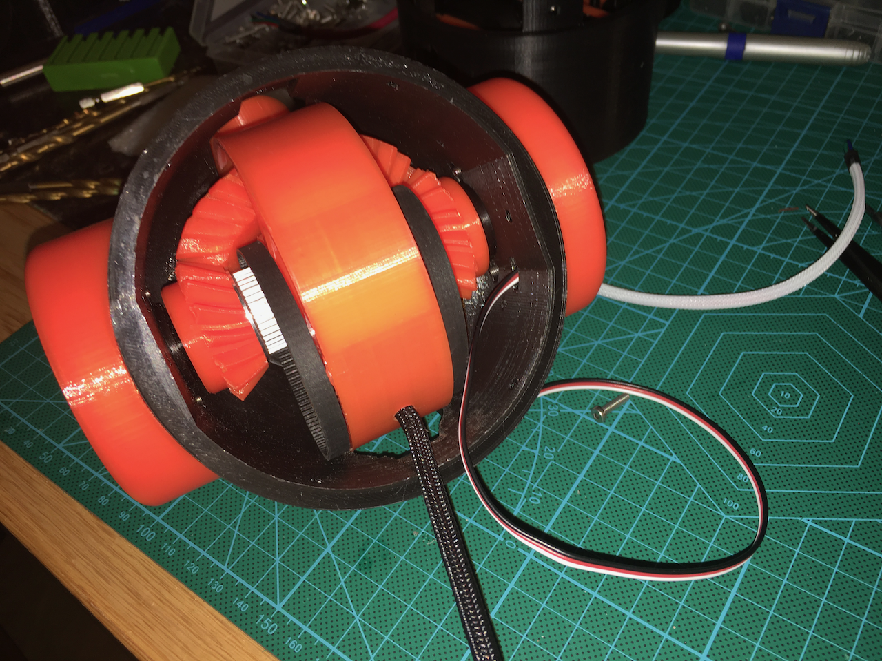
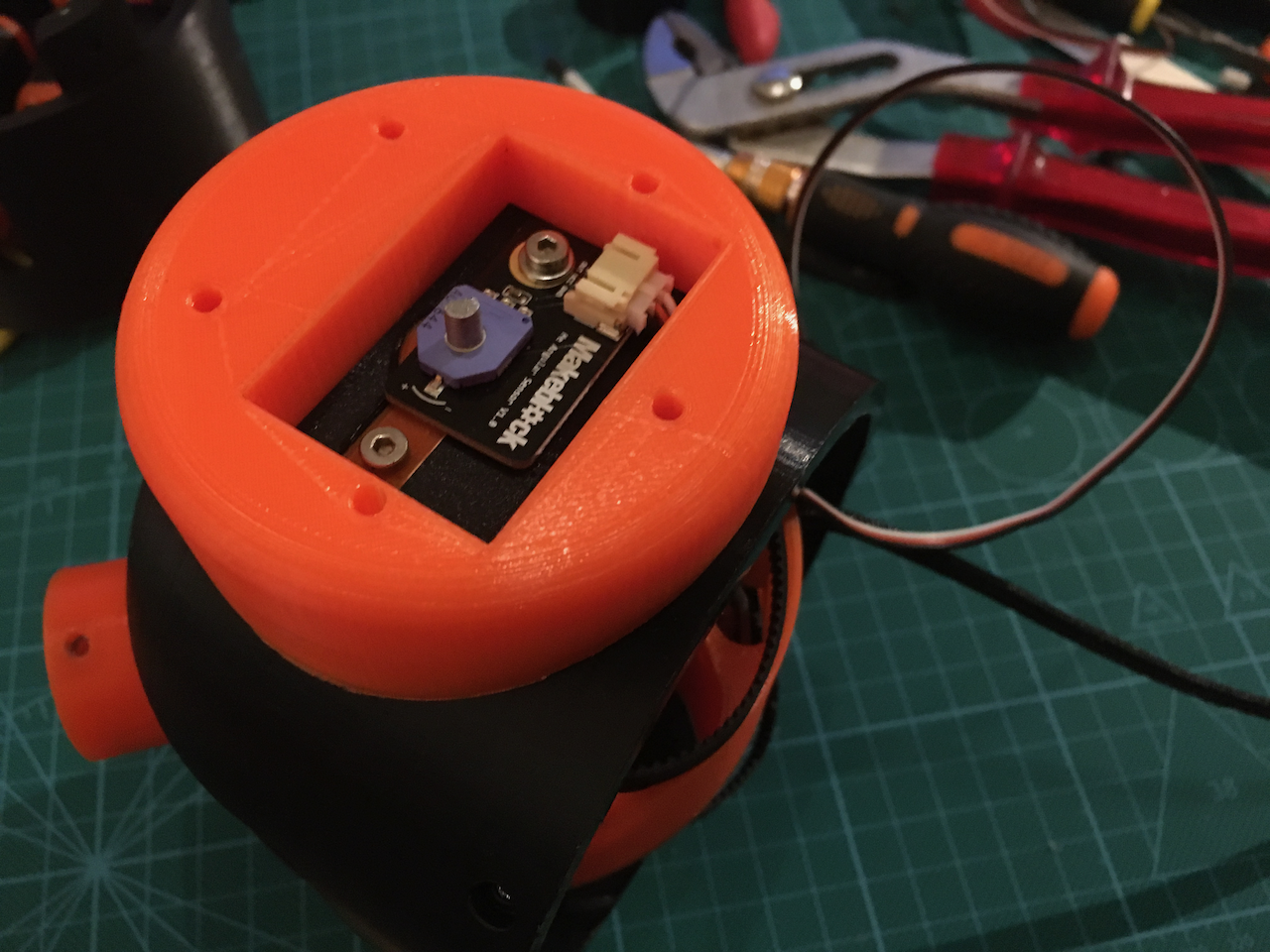
I used two rotation sensors on the Art56MotorCoverRing
Everything mounted. Look at the two new black spacers on the outside of the axle.
The STL's and design files
Below the latest step files and stl's of al the new and changed parts.
The bearings I used are 6806 2RS (30x42x7mm) and 6810 2RS (50x65x7). I ordered them for 21,50 euro including shipment from lagerkonning.nl.
Next: Another redesign to fix a problem.
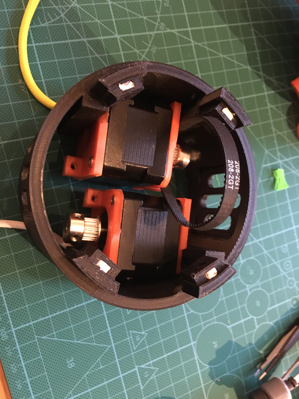
With the new setup I have created a small problem. There just isn't enough room for all the wires. I am going to change Art4LowerBody again. I am going to add some room on the bottom and top of the motors. The two 208-2GT belts are going to be replace by 232-2GT belts. This way I have 12mm of extra room for the Art56MotorCoverRing Sensor wires.
On the bottom of the motors I want to add another 12 mm for a small pcb with some connectors to connect everything.
By lengthening the Art4LowerBody by about 25 mm it will be easier to mount and wire everything. I might also add a inner wire guide to prevent the wire toughing the belts or pulleys.

Discussions
Become a Hackaday.io Member
Create an account to leave a comment. Already have an account? Log In.
I'm putting together Art56 and have a couple of questions. Are the small gear/pulley assemblies free to spin on the axles or are they fixed by the set screw? If they're fixed the the axles have to spin in the Motor Cover Ring. That doesn't seem like such a good idea since there's no bearing. If the assemblies are fixed to the motor cover ring then there's no need for two MakeBlock angular sensors since both axels are connected.
Are you sure? yes | no
The small gears are free to spin. They are not fixed to the axle.
Are you sure? yes | no
I am going to print your parts :-)
I do it in NGEN
Are you sure? yes | no
Nice!
Are you sure? yes | no
Fantastic work!
Are you sure? yes | no
Interesting to see how one idea can lead to many other variations of ideas.
Are you sure? yes | no
I wanted to add some stability to Axle 4. And now it is rock solid. After fixing the last problem as described I will start wiring and then it is time to start programming and testing.
Ps. I just upload a second version of the day 18 zip. I updated the design files.
Are you sure? yes | no
You are still using PETG for all of this?
Are you sure? yes | no