 Sepio
SepioCalibration tip
The external Nextion display is finally printed. I had some calibration problems with my printer. All rectangle where shaped as diamonds. I tried to calibrate the printer multiple times but every time i measured the corners with a geo-triangle they where not perpendicular.
After a while I really didn't understand why it wasn't working. Then I laid the test print on the green cutting mat and it was already perfect the first time. The only corner that wasn't perpendicular was that of the cheap chinese geo-triangle......
My free tip. Don't use a cheap chinese geo-triangle for calibration purposes. That doesn't work ;-)
External display
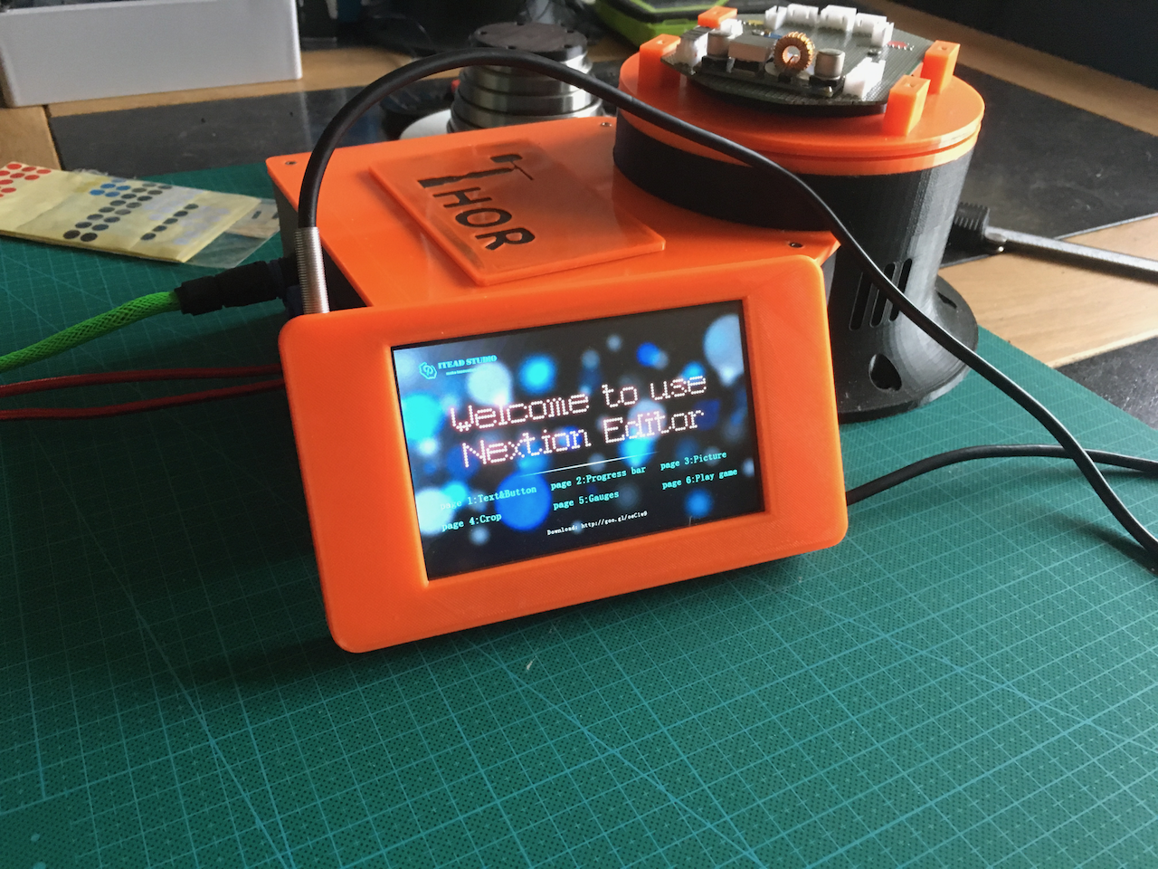
In my previous log I already told that I moved the display external. Now its finally printed and its available below.
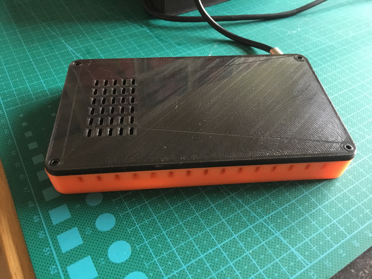
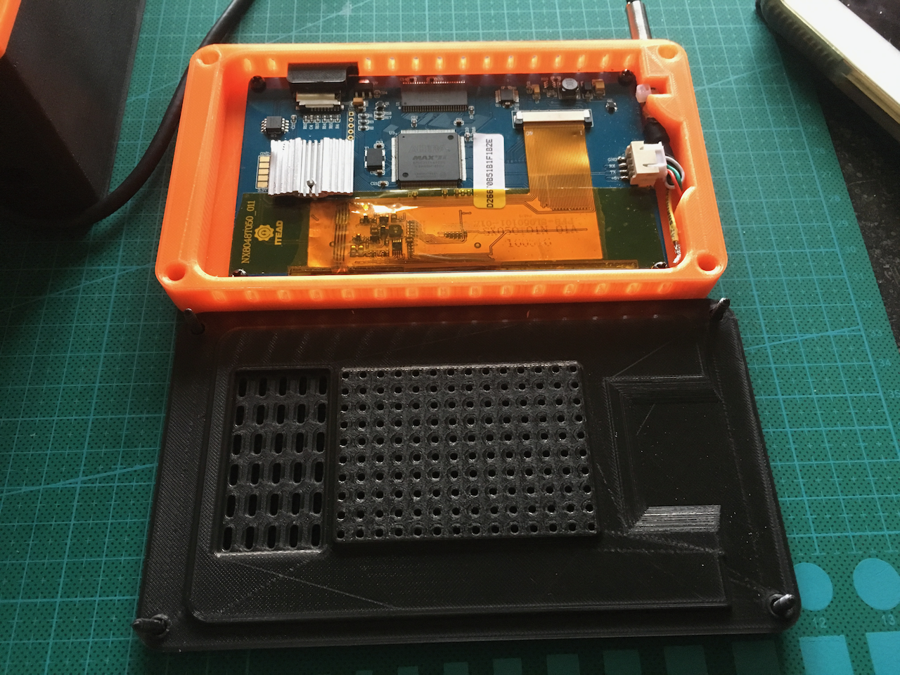
The display chips become extremely hot so I created some vent holes on the top, bottom and on the back. This makes it possible to lay it flat on the table or put it upright.
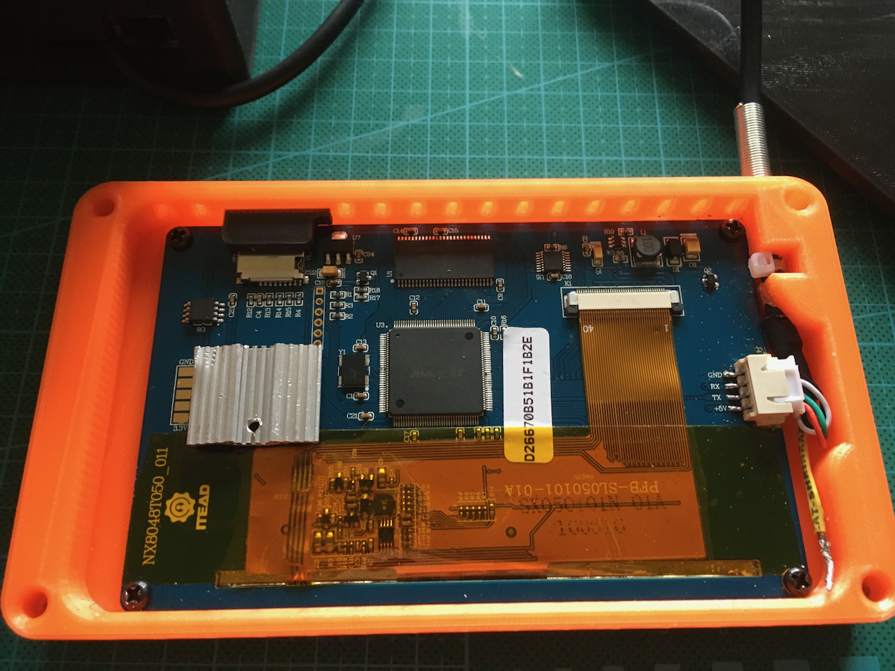
On the inside there is a small black cover on top of the SD card reader. The cable is fastened with a tiewrap. I also dit put a flattened transistor cooling fins on top of the CPU? Its becomes extremely hot.
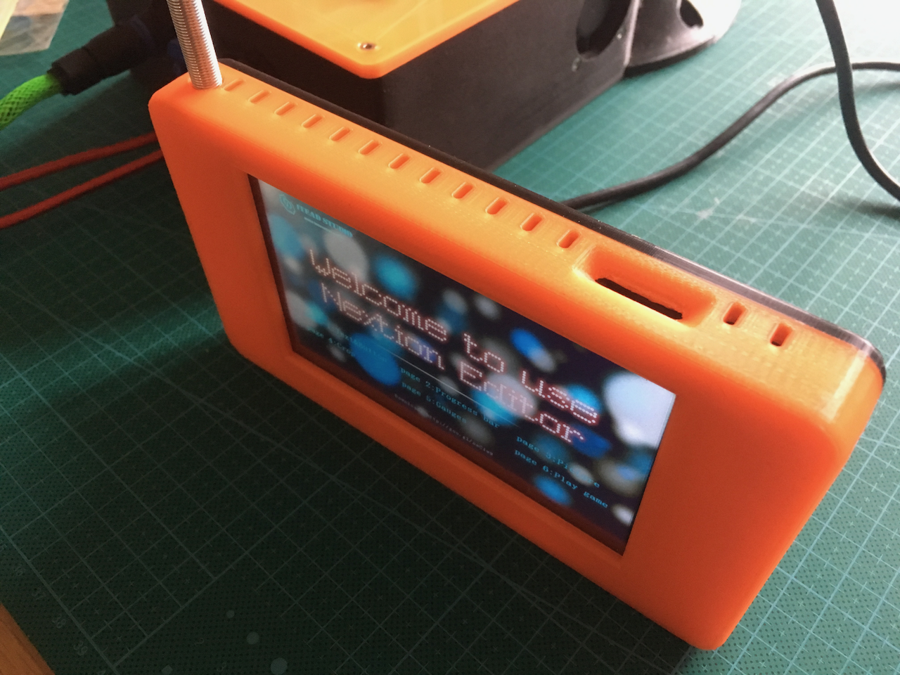
This is the top of the display. The big hole is for the SD card. I used a spring as a strain relief on the cable. Its also possible to use some heat shrink tube.
 On the back of the back panel there is a square (with all those small holes). This adds some structure and it can also be used to screw a custom mount on the back.
You can use self threaded screws or "5mm long m3 Threaded Brass Knurl Round Insert Nuts" to mount the back to the front (just put them on a long screw and user a lighter to warm the nut. Then press it into the hole. The m3 nut is 5.5 mm the hole is 5mm..
The new version can be download here. It also still includes the previous version with the display on top.
Discussions
Become a Hackaday.io Member
Create an account to leave a comment. Already have an account? Log In.
Nice, what size of display do you use?
I am also trying to build my own holder (I want to design this one myself). I was thinking about using a DB9 serial connector instead.
The heat issue is something I did not expect, so I am warned.
Are you sure? yes | no
I use the Nextion nx8048t050. I am thinking about using a DIN Connector. They are also round and they are cheap. I also bought some of those buccaneer connectors from Conrad. But they are expensive..... I don't want to buy more.
I wasn't expecting the heat also. The version in the rendered preview I posted a few weeks ago wasn't having ventilation holes. So this is the printed version 3. Also leave enough room to centre the display.
If you still have to buy the display then don't. It's expensive. I don't like the software, the documentation is mostly bad or missing and the display can only be operated correctly with a pen.
Are you sure? yes | no
I think that is the 5 inch. The pixel resolution is the same as the 7 inch. I have the 7 inch version. I did have my issue with their software that is clearly still in alpha state.
The pen or in my case my finger nail was the first thing I noticed.
I actually started to rewrite their software on the Arduino to make it more easy to program in the Arduino. I still did not get any chance to continue it.
Are you sure? yes | no