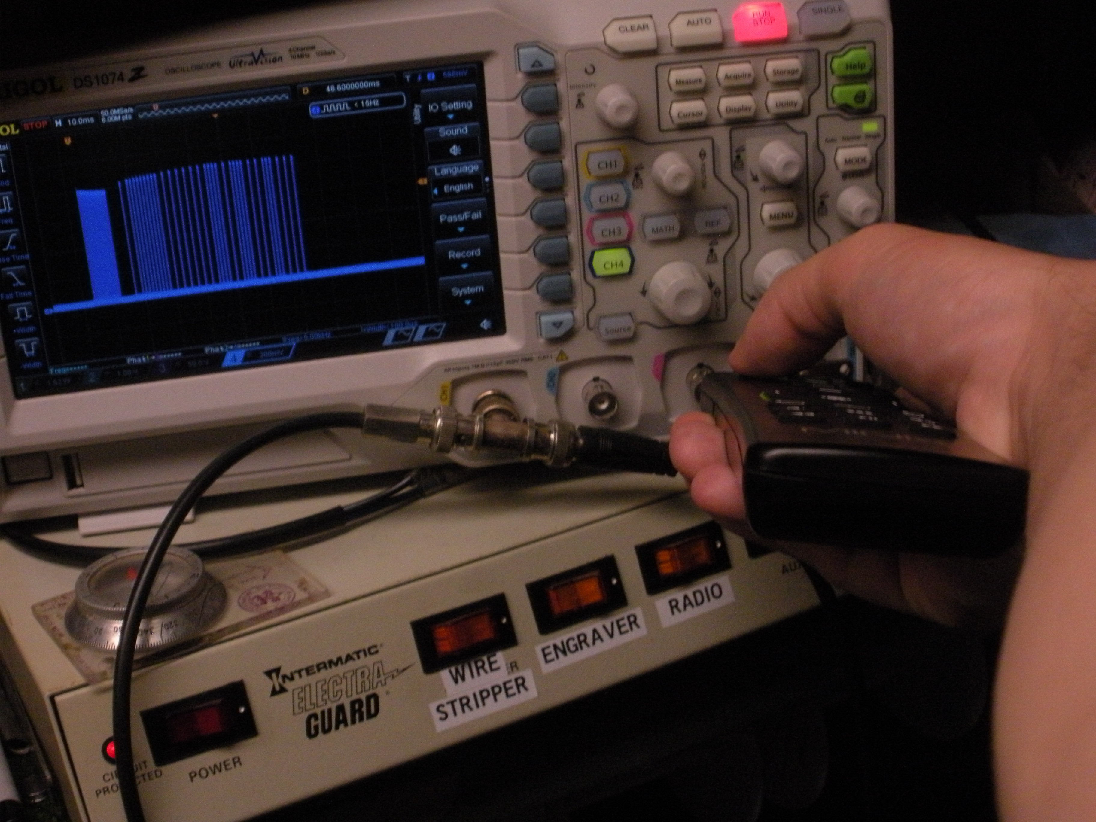
• Enclosure built, project complete

    Clara Hobbs08/29/2017 at 15:55 0 comments

    I modeled an enclosure yesterday evening, and much to my surprise, everything fit perfectly on the first try!

    The IR LED fits through a large hole allowing it to be aimed anywhere from horizontal to vertical.  There's a small window for the IR receiver, and a light pipe made from a piece of 1.75 mm T-Glase filament to show the green LED (simulated in the picture; the camera flash completely washed it out).  The USB cable is only used to provide power.  The two halves of the enclosure just friction-fit together, so it's easy to get the guts out for re-programming if I ever need to.

    I could go a bit further with this project, designing a circuit board and writing complete build instructions.  But I really don't know if anyone else wants a device like this, since usually a universal remote control is a perfectly good solution for consolidating several remotes into one.  So unless I see strong interest in polishing up this project further, I'll just call it complete.

  • Parts arrived, built on perfboard

    Clara Hobbs08/28/2017 at 20:52 0 comments

    I ordered parts to build this thing more permanently, and they arrived today.  The IR receiver is a TSOP38238, which works on 3.3 V (no more dropping diodes!), and the LED is a TSAL6400, which has known specs allowing me to calculate the right resistor to get about 20 mA (roughly 120 Ω).

    Now all that's left to do is make an enclosure for it.  I'll be sure to leave a nice big hole for the LED to fit through, so its leads can be bent to aim at the TV's IR receiver.

  • Small Reliability Improvement

    Clara Hobbs08/26/2017 at 18:52 0 comments

    Yesterday I found a minor bug in the firmware.  When the translator saw the NEC power signal, then saw some other signal before the receiver stopped seeing anything, an odd state was reached.  The translator would have its LED stuck on, and it would never transmit the RC5 power signal.  I looked into it today, and found the cause.  Every time a code was received, we checked that the signal was still correct.  If it wasn't, the LED wasn't turned off and nothing was transmitted.  Therefore, the last code in a burst had to be correct for translation to be completed.  That's not the best behavior though, since once we've seen a power code we know the button has been pressed, so we should transmit as soon as we can.  The fix was very simple, and has been pushed to the repository.

    In other news, the parts to build a more permanent unit should arrive on Monday.  I'll be able to get this thing off of a breadboard, onto some perfboard, and into an enclosure!

  • It works!

    Clara Hobbs08/18/2017 at 18:20 0 comments

    My STM32 "blue pill" boards arrived yesterday, and I started hacking away at some firmware.  I combined a couple different examples I found online and made the damned thing actually work.


    The IR receivers I had on hand all required 5 V, so I used two diodes to get a safe level for the microcontroller.  The electrical tape is just to make the power LED less obnoxious.  Soon I'll buy parts specifically for this project and build it in a more permanent way, and I won't need those diodes anymore.

    The last example linked above, the IR reading code, needed some work.  Mr. Guglielmi reverse-engineered the NEC protocol, apparently not bothering to find out exactly what protocol he was reverse-engineering.  As such, some of his timings were wrong, and his code needed a repeat signal to be sent before it sent an event telling the rest of the code that a button press had been seen.

    I fixed those problems last night, and the device works pretty well now.  You can check out the firmware from my Git repository, and the one C source code file says what pins are used.  I might release a more formal hardware design if anyone else is interested in making a device like this.

  • Remote Control Signal Reverse Engineering

    Clara Hobbs08/15/2017 at 16:43 0 comments

    The first step for this project was to figure out just what exactly the two remote control codes involved are.  To do this, I built an ugly version of the "silver bullet".


    With this new weapon at hand, I pointed a remote control at it and pressed the power button.  A pretty nice signal appeared, which I recorded on the scope and analyzed.

    After a bit of research, I determined that this is the NEC Infrared Transmission Protocol.  With this knowledge, I easily decoded the address 0x80 and data 0x18.  I'll have to listen for this signal, and transmit the other remote's power button code when it's received.

    Speaking of which, what exactly is the other remote's signal?  Using a similar technique, I found that it was using the RC5 Infrared Transmission Protocol.  The address is 0x00, and the data is 0x0C.  All the signals from this remote control seemed to be at about 106.6% of the normal speed for RC5, which interestingly made the carrier frequency 38 kHz instead of RC5's normal 36 kHz.  Whether this was intentional or not, I don't know.  Since this is the signal I'll be generating, I can try it both ways to see if the TV receives either one significantly more reliably.