Close
0%
0%

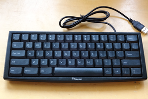
Using 4×4 Keypad With Arduino

Keypads are used in all types of devices, including cell phones, fax machines, microwaves, ovens, door locks, etc.

Similar projects worth following
Keypads are used in all types of devices, including cell phones, fax machines, microwaves, ovens, door locks, etc. They’re practically everywhere. Tons of electronic devices use them for user input.

So knowing how to connect a keypad to a microcontroller such as an Arduino is very valuable for building many different types of commercial products.

At the end, when all is connected properly and programmed, when a key is pressed, it shows up at the Serial Monitor on your computer. Whenever you press a key, it shows up on the Serial Monitor. But for now, for simplicity purposes, we start at simply showing the key pressed on the computer.

For this project, the type of keypad we will use is a matrix keypad. This is a keypad that follows an encoding scheme that allows it to have much less output pins than there are keys. For example, the matrix keypad we are using has 16 keys (0-9, A-D, *, #), yet only 8 output pins. With a linear keypad, there would have to be 17 output pins (one for each key and a ground pin) in order to work. The matrix encoding scheme allows for less output pins and thus much less connections that have to be made for the keypad to work. In this way, they are more efficient than linear keypads, being that they have less wiring.

code_for_using_keypad_on_serial_monitor.ino

Remember to install the library first!

ino - 1.04 kB - 08/13/2017 at 15:27

Download

  • 1
    Understand the Keypad

    One of the most mysterious things about these keypads is that they usually come with no documentation, so a user is left to figure out the pin configuration for him or herself. However, we at this site, have figured it out.

    With the keypad facing up so that the keys are up and facing you, from left to right, the 1st 4 pins are the row pins and the last 4 pins are the column pins.

  • 2
    Connections

    Connections of this project are straight and simple as shown above.

    • Connect pin 1 of keypad to pin 9 of Arduino.
    • Start connecting the pins leftwards now. 2 with 8, 3 with 7, 4 with 6, etc.
  • 3
    Uploading Code

    Now, upload the program and open the Serial Monitor. Then, open the Serial Monitor. Then, press any button and you will be able to see the corresponding character of the screen.

    For further help, you can go to this link which will run the simulator made by me on Tinkercad for more easy understanding.

View all 3 instructions

Enjoy this project?

Share

Discussions

Similar Projects

Does this project spark your interest?

Become a member to follow this project and never miss any updates