 Enrico
The issue
When I started to breadoard the lamp, I was using this PCB, carrying on the LEDs (from now on called LED engine). The one shown in the breadboard was this one:
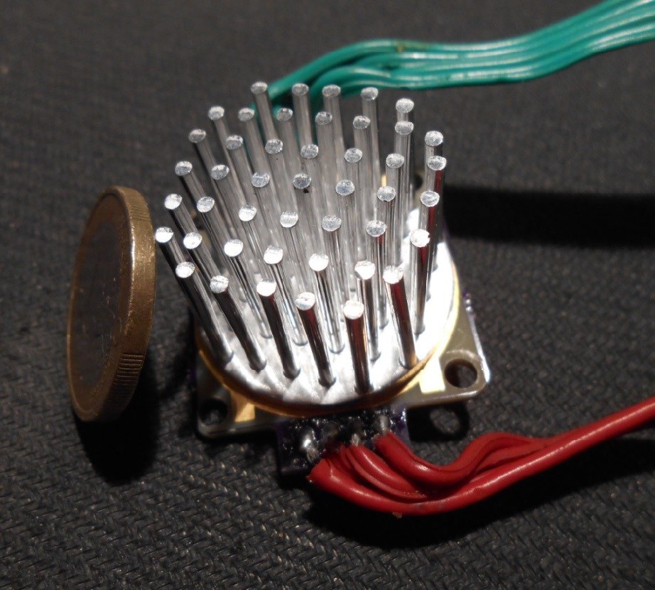
Chosen to reach, according to thermal analysis of the LEDs (from datasheet) and the given suggested thermal pad on the PCB, no more than somewhere 70°C at full power.
Making this in reality shows that my calculations were imperfect: the heatsink could reach almost 75°C and more, showing that this thermal pad
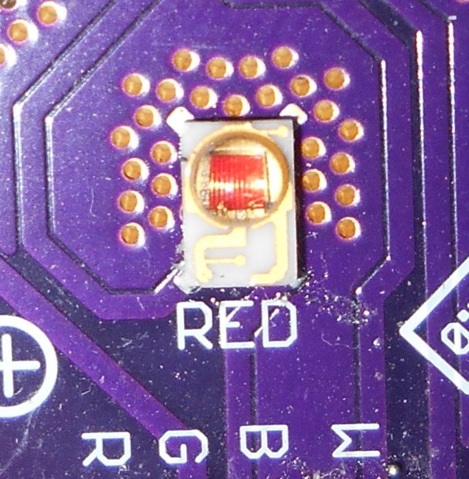
wasn't probably conceived to be thermally closed within traces as shown in the picture. I say this because was the only variation from the specified layout: even the right amount of copper was used, according to the application engineers. The calculations were simply done in this way:

Where the case-heatsink term is the thermal resistance given from the LED pad design provided from the application note. But what in the end make me realize that calculations were even more far, is that the LED power were overestimated, because I assumed that all the power is generated in heat, while in reality the LED have a given efficacy (around 30/40%), meaning that the 40% of power is generated in light and not in heat (well.. the heat is light per se, but not useful here). So in reality, it shall be even 40% cooler than it was.
In the end, I also realized that if such heatsink shall be touched (I want to use those LED at desk height ideally), even 70°C were too much, forcing me to use either a fan (but I am against them were their usefulness is not proven) or a bigger heatsink.
The monster
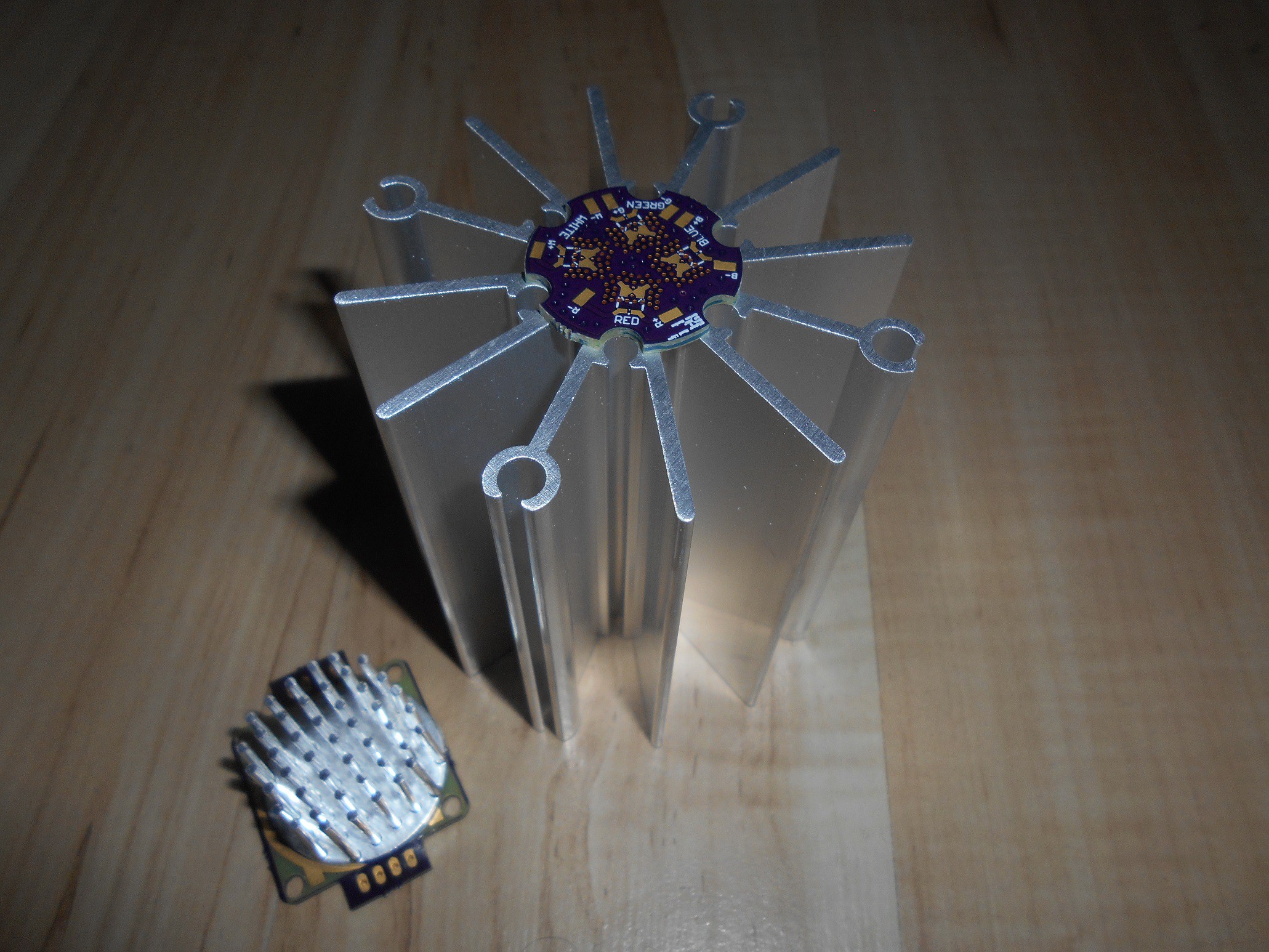
When you get betrayed by a small heatsink, you go big. So I decided to look for some nice heatsinks available, and made a board for them. I came out with the third revision of the LED engine, as big and round as a coin, overcompensated with an heatsink beneath it.
The big size has also the purpose of being helpful for supporting mechanically the lights somehow. As you can see from the picture below, designing the PCB was quite interesting too:
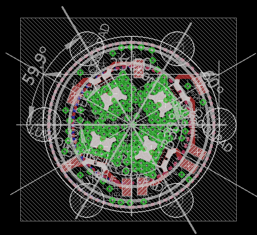
The little brothers
When I was taking a picture of the big one, I have also realized how many attempts I've made in the past. You can see them here one next to each other:
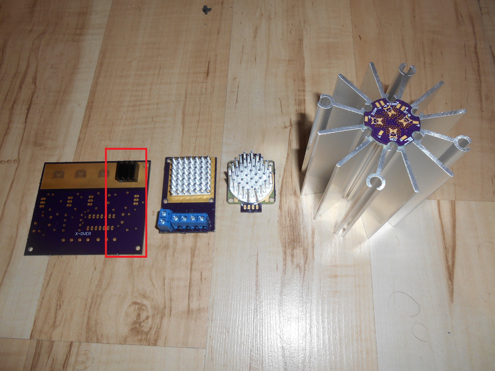
On the left, the first ever board made was described in detail here. It was a first design trial implementing a linear LED driver, with firsts experiments with OSHPark and SMD soldering. Despite errors and imperfections, each LED was surprisingly cooled.
Then the second attempt, still with a linear approach, with a different layout was described here and corresponds to the second from the left.
The third one is the one used up to now and the biggest one is the final revision. Actually, there was a middle version of a bigger heatsink in the second revision of the LED engine, just to get things done, from a previous project:

After this refreshing (with heatsinks.........) update, I can go forward with the assembly of my lamp, while improving the firmware. Stay tuned!
Discussions
Become a Hackaday.io Member
Create an account to leave a comment. Already have an account? Log In.