 Bradley Gawthrop
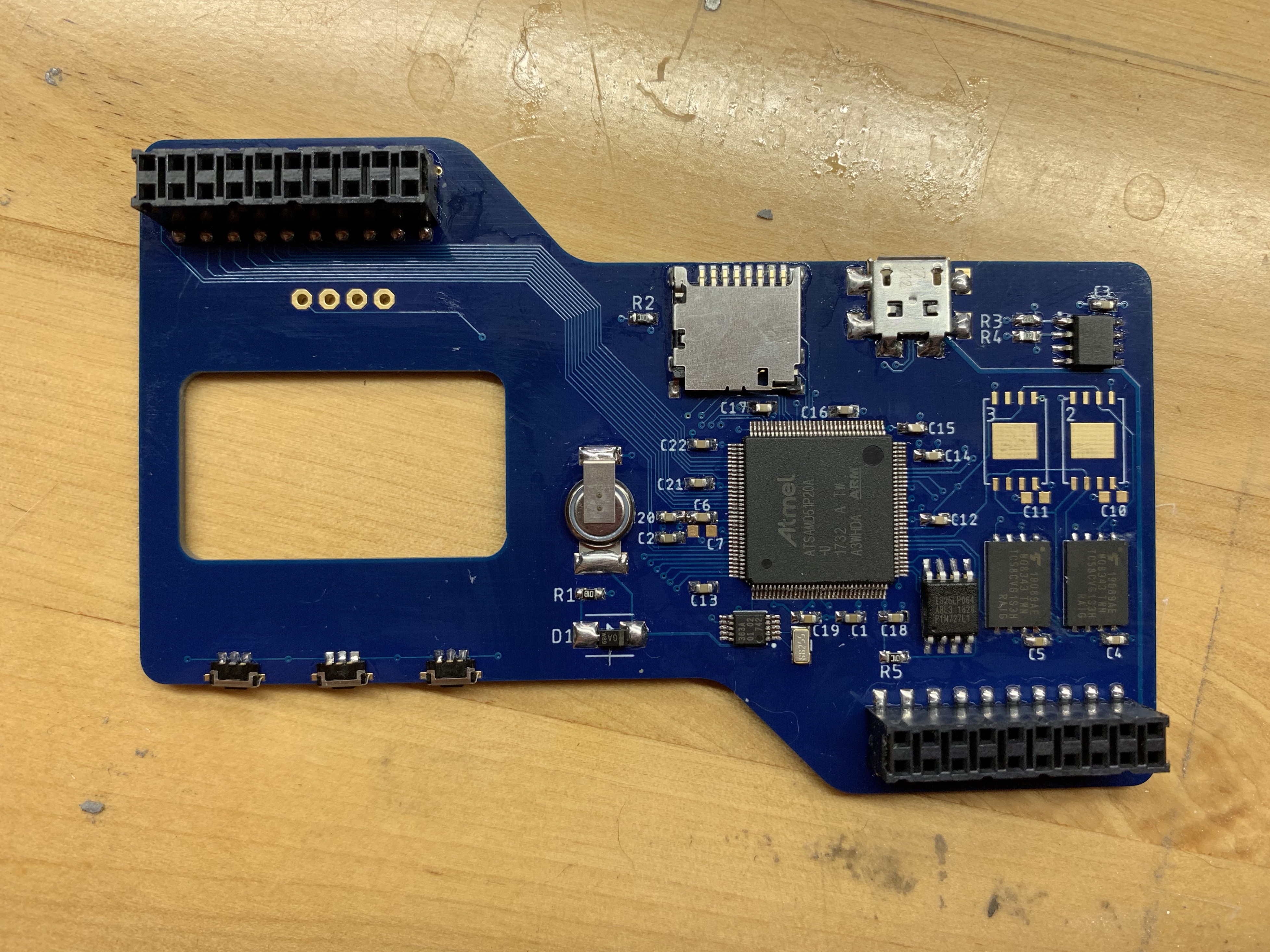
With a general architecture established, Upper seemed like the obvious choice for a first build. One of the first things to think about was Swamp Finger.

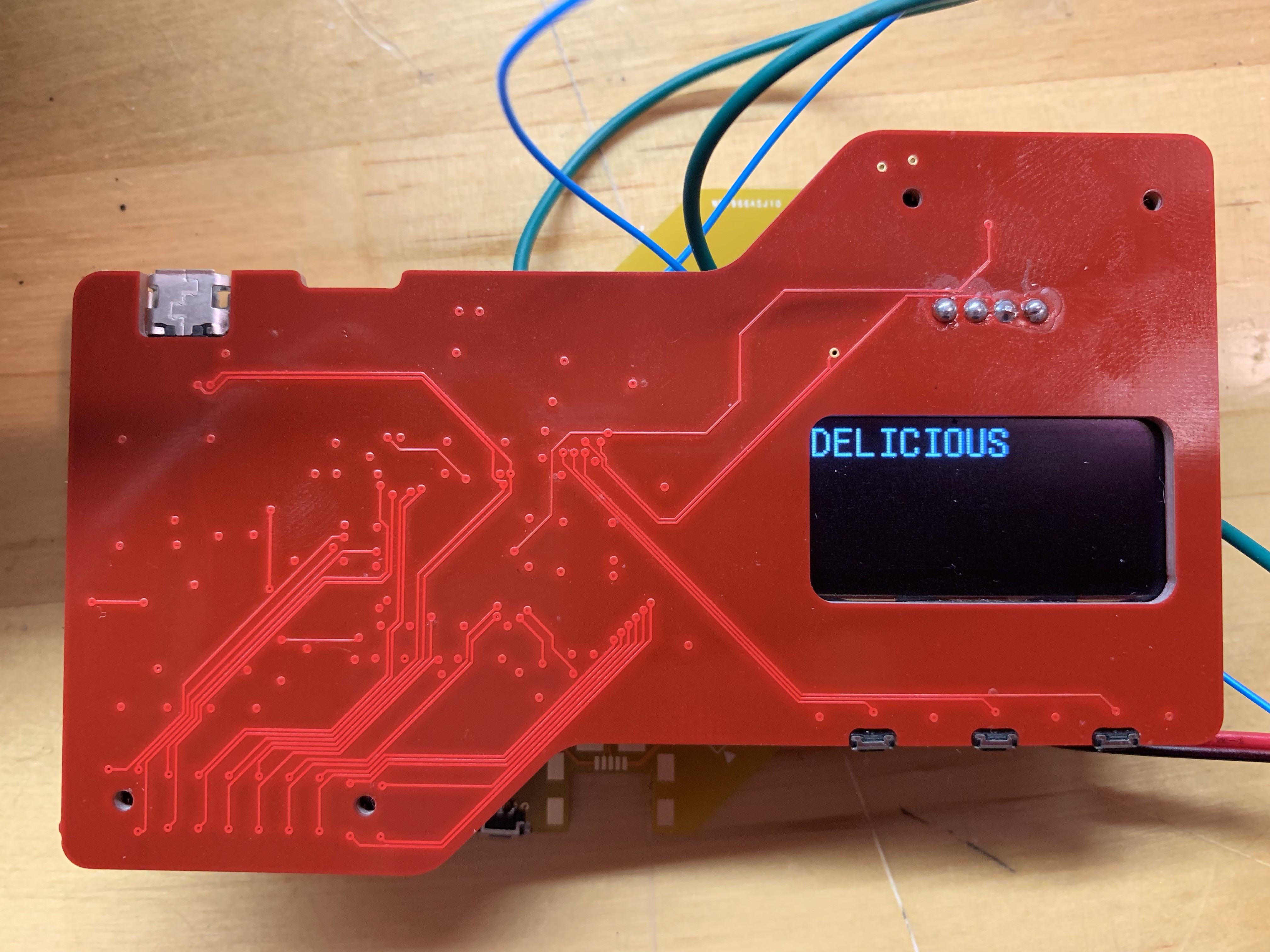
FieldKit stations go to unfriendly places. They typically live in water-resistant enclosures, but when those enclosures do get opened, the conditions may well be less than ideal. The hand reaching in, to probe at the delicate electronic guts may well be dirty, wet, or clumsy. Jacob coined the term "swamp finger" to describe the hazards of living in these environments. This immediately ruled out otherwise attractive options like capacitive sense 'buttons', but it also led to one of the more striking design decisions of the process, which was to place components only on the inside of the sandwich made by Upper and Lower, where no swamp finger is apt to roam.
This somewhat complicated our desire to add a screen. Previous FieldKit hardware attempted to indicate all needful data with LEDs. This is not ideal in the field, or for that matter, for battery consumption, so the plan was to go with one of the ubiquitous I2C OLED displays which have been in so many projects in the last few years. Since we were only populating the invisible side of the board, this meant reverse-mounting the OLED display and cutting a window in the PCB so that it could be seen from the other side.
Then it was just a question of choosing the right tools for the job :
Storage
Once upon a time, we relied entirely on the SD card for storing the data gathered by FieldKit stations when deployed. The price is right, but as anybody involved in #badgelife can tell you, SD cards are The Worst and probably not to be trusted for mission-critical jobs of that kind. Darwin needed on-board memory, so we put in four slots for high capacity SPI NAND flash. We typically use 2Gb chips, giving us a 2-8Gb installed range, depending upon need. The SD card is now for backup and contingency offload if the radios fail.
Microcontroller
The ubiquitous ATSAMD21 series had served us well, but we were entirely saturated for pins and memory. That said, we didn't want to leave the Atmega Cortex line entirely, as community support for and understanding of the chips is very good, so we ended up with the biggest of the line, the ATSAMD51 in a 128 pin TQFP package. Bring me all your pins and RAM!
In support of the ATSAMD51 we installed a fairly hefty QSPI flash chip for bootloader duties.
RTC
In theory, we could have used the internal RTC on the ATSAMD51 for RTC duties, but prior experience made me slightly gunshy on that point, so we used an external RTC, and supplied a supercapacitor to serve as its 'battery' backup. Previously, we've used CR2032 cels for this, but the irony of making a conservation-oriented product with primary lithium batteries struck us as a little hard to justify. Since this RTC also had clock out, we used it to pump a clock into the microcontroller and only needed the one crystal.
MISC
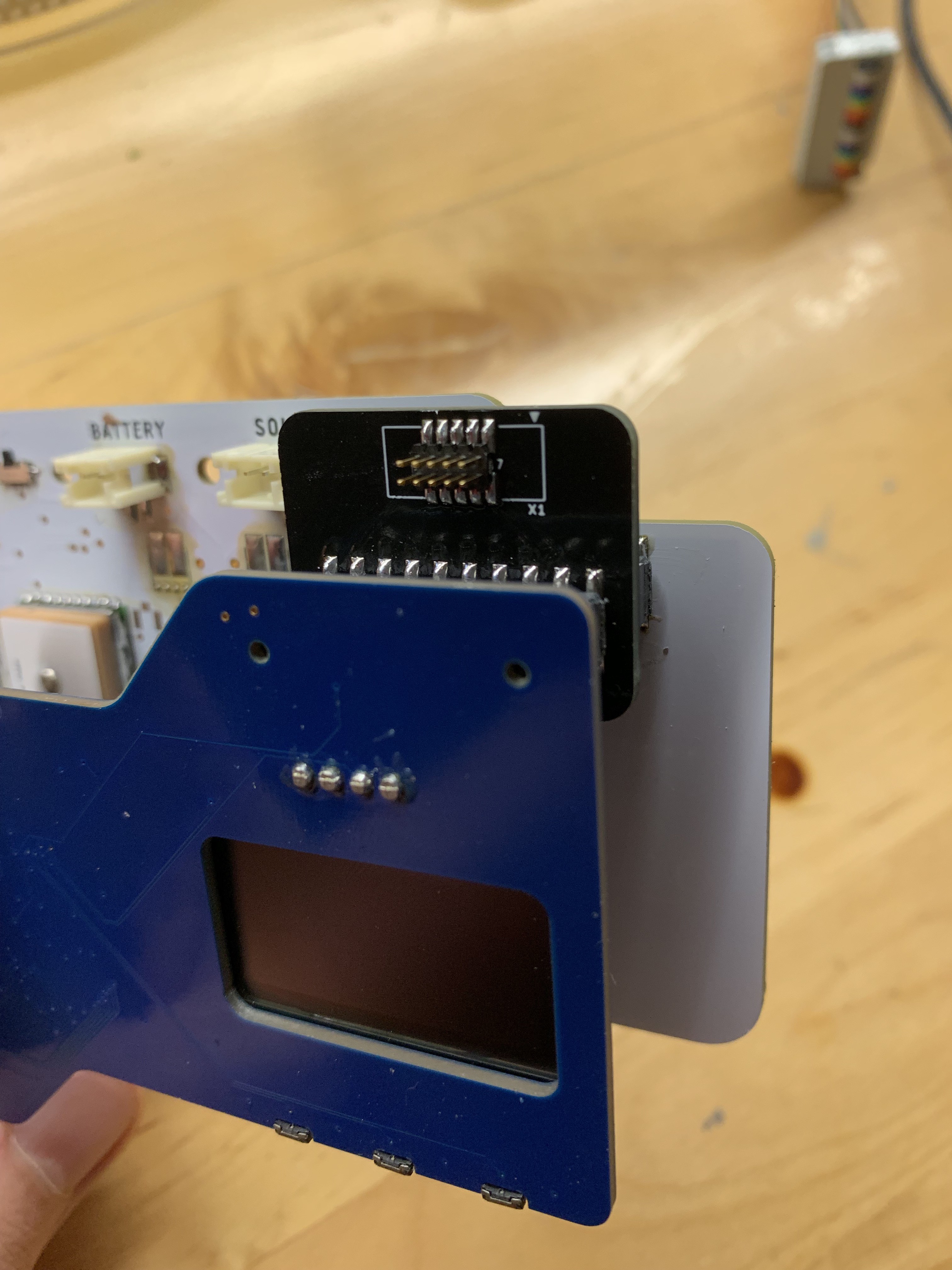
2.54mm pitch box headers seemed like a natural choice for mezzanine connections between Upper and Radio. They are ubiquitous, durable, and tall (the GPS module is a big boy).
What about a programming header? Well, we decided not to have one. All the pins required for programming are on the mezzanine connector. Batch-programming jigs were always in the roadmap anyway, and for in-circuit debugging, well, Jigs Ahoy!
In the interest of monitoring and predicting battery life in cold conditions, we added an inexpensive temperature sensor as well. Thought it looked cute, might delete later.
Next up : Radio!
Discussions
Become a Hackaday.io Member
Create an account to leave a comment. Already have an account? Log In.
Which OLED display did you use and exactly how did you go about reverse mounting it?
Are you sure? yes | no
Replied in DM.
Are you sure? yes | no