 Jacob Lewallen
In our previous post, Shah outlined our most recent project with the Tropical Rivers Lab at Florida International University and gave a high level overview of the work we've started with them. I wanted to take some time to talk about how valuable the real world work is in providing feedback on FieldKit ecosystem.
It's inevitable in field work that you'll find yourself working with conditions or constraints that you didn't anticipate, even more so when you're the one who has designed the hardware you're using. Ever since my first field experience I've tried my best to keep meticulous notes on the issues I encounter, their solutions, and ways they could be avoided and mitigated in the future. These notes are incredibly valuable compared to in-lab testing of hardware and physical enclosures by virtue of many important facts:
- They are often taken outside of the lab, without access to the tools and parts that are available during development.
- They include insight from volunteers or partners that aren't present during the day to day in lab testing.
- Not every field installation is identical and always brings some unique challenge to bear on the hardware.
- There tends to be a difference in scale that has an impact on my mindset. For example, assembling 10 stations is very different than assembling 1 for an in-lab test, making bottlenecks and physical improvements more obvious.
I'm going to quickly go over some of the changes we've made recently, directly due to the efforts of preparing these stations for the field.
Physical/Hardware Changes
Size
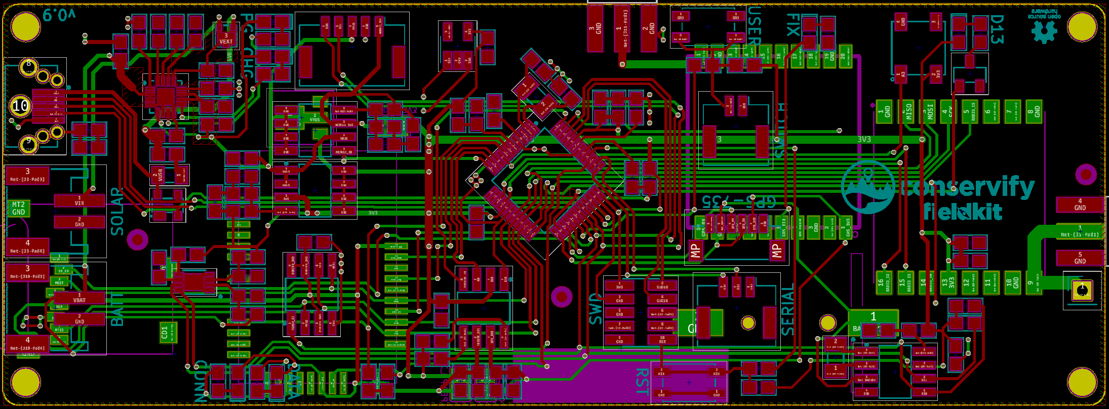
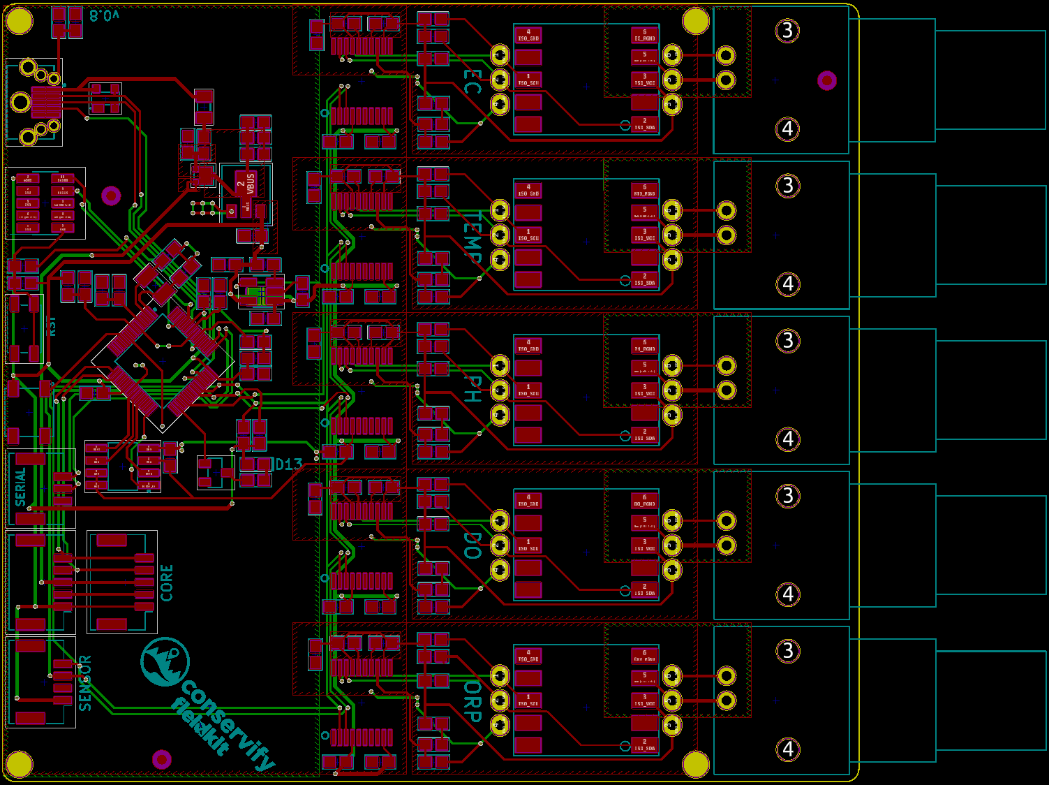
Board sizes evolved haphazardly until recently. I've begun rounding them to easy to remember dimensions.
Connectors
Oh connectors. Connectors have been one of the largest frustrations I've had. We've recently begun incorporating Molex connectors on our boards to link modules to the Core board. The connector is a 5 position one, carrying I2C, power, and Vbus (unused for now) This went so well that one change I wanted to make was use them for even more things, not just the Core/Module connection. We decided to increase our use of these connectors in these ways:
- These stations were the first to incorporate an external user switch, which was exposed via an awkward through-hole header. This became a 2 position Molex.
- Weather stations have two PCBs, one main weather module and a board we call the sensor board that's housed in a Stevenson screen. One end was already Molex and for some reason the other end was not. These things happen. The learning experience here though, was that the Molex on the sensor board should be on the bottom of the PCB for easier mounting.
- Our water quality module had a 4-position "sensor" connection already. We carried this pattern across all our module boards because it's become common to attach secondary sensors to various modules.
- We added second Core connectors to all modules so they could be daisy chained in the future.
Vertical Entry vs Side Entry

So far used we've been using side-entry USB and JST connectors exclusively. Somewhere around the third board I realized that vertical entry USB would be way more useful in situations where the enclosure is an off the shelf box. Side entry, especially on the ends of boards, requires internal space to be be able to use the connector. Otherwise, you've got to lift the board from inside the enclosure to insert a USB cable when flashing or charging, etc.. The same goes for the JST connectors we used for batteries, though to a lesser extent because they tend to be more maneuverable than USB cables. Right now we're testing hybrid USB and JST footprints that allow either part to be soldered on. We'll be reporting back on how successful this is, especially with regard to the frankenprint we're using for the USB.
We'll also be moving to vertical buttons, as well.
Connector Locations
Our solar panel JST was on the bottom of our Core board, simply because room for connectors tends to be pretty limited. This was annoying, and so future boards will have the connector on the top.
We are also striving to keep connectors and LEDs grouped to facilitate stacked mounting situations. For example, we mounted the Core board over the Atlas Water Quality module, leaving the latter's side exposed where nearly all of the connectors were. This was very nice, and could have been nicer if all the connectors were along that edge.
Mounting Holes
Our mounting holes are pretty small, a symptom of them appearing so large when laying out boards in Kicad. This made the hardware frustrating to use and in at least one case there wasn't enough clearance for the nut because of PCB parts. So all boards got 2.54mm diameter mounting holes with special attention paid to clearances. Another change we're hoping to make is standardizing the pattern across modules and Core to make mounting easier.
Solar Panel Hardware
We use Voltaic panels pretty much exclusively at this stage. We learned far too late that Voltaic has a number of accessories that can make their panels more pleasurable to work with:
- Extension cables with various connectors. Notably JST and exposed leads. This is nice because we often attach panels in the field during installation and being able to dangle the extension outside of the enclosure makes that process easier.
- Stainless steel post nuts. Anybody that's used these panels has probably been confused by the plastic nuts they ship with.
- Mounting brackets and corner mounts. They even provide designs so you can fabricate your own. Mounting these panels to enclosures is a task that's only just now finding some solid ground, until recently it's been one of the uglier tasks.
Status LEDs
Our boards have typically included three status LEDs arrayed the same way on all boards. This didn't pan out exactly the way I had intended and so we've decided to try out the Neopixel status LED like you're seeing on newer boards from Adafruit and the Particle boards.
Software Changes
By the assembly stage the software is mostly pinned down, but a few things came up in my notes.
One of the sites we'll be deploying to in the future will have Wifi, which is a first for us and means there's some things I'd like to have ready to go for that installation. Specifically, the ability to remotely upgrade firmware. This has been one of my focuses over the last week. This has meant a custom bootloader that can read firmware from our serial flash chip into the flash of our MCU. With that in place we've got other sever-side infrastructure for deploying firmware binaries from our Jenkins/CI server to the cloud where they're cataloged. It's now possible to set the firmware on a per-device basis, and devices will download that firmware on a pre-defined schedule. Next steps here are being able to flash modules, which is slightly more involved because the firmware has to travel from the Core module Serial Flash to the Module's Serial Flash.
I've been unhappy with our internal scheduler and so moving to something more flexible has been important. We've recently introduced a new "Cron-Like" scheduler for tasks.
Next Steps
Right now my focus is on the remote firmware flashing and testing the hardware changes outlined above. We're also doing some research into replacing our voltage regulation section due to supply chain issues and we'll have a future post on that frustrating experience. Until next time!
Discussions
Become a Hackaday.io Member
Create an account to leave a comment. Already have an account? Log In.