 PremJ20
In our system design the components used are:
- Flex sensor
- 3-axis accelerometer
- Particle photon
FLEX SENSOR:
This flex sensor is a variable resistor like no other. The resistance of the flex sensor increases as the body of the component bends so on one side of the sensor is printed with a polymer ink that has conductive particles embedded in it.
Left flat, these sensors will look like a 30kΩ resistor. As it bends, the resistance between the two terminals will increase to as much as 70kΩ at a 90° angle.
By combining the flex sensor with a static resistor to create a voltage divider, you can produce a variable voltage that can be read by a microcontroller’s analog-to-digital converter.
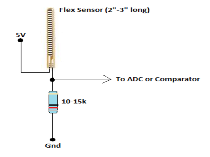 Flex sensor circuit
In our project the flex sensor is used to measure the flex angle between knee joint and lower leg.
3 AXIS ACCELEROMETER (ADXL335):
An accelerometer is an apparatus used for measuring acceleration or deceleration - that is, the rate of increase or decrease in the velocity of a moving object. Accelerometers are used to measure the efficiency of the braking systems on road and rail vehicles; those used in aircraft and spacecraft can determine accelerations in several directions simultaneously. The measurement of acceleration or one of its derivative properties such as vibration, shock, or tilt . In our project a 3 axis accelerometer is used i.e ADXL335.
The ADXL335 is a small, thin, low power, complete 3-axis accelerometer with signal conditioned voltage outputs. The product measures acceleration with a minimum full-scale range of ±3 g. It can measure the static acceleration of gravity in tiltsensing applications, as well as dynamic acceleration resulting from motion, shock, or vibration.
The user selects the bandwidth of the accelerometer using the CX, CY, and CZcapacitors at the XOUT, YOUT, and ZOUT pins. Bandwidths can be selected to suit the application, with a range of 0.5 Hz to 1600 Hz for X and Y axes, and a range of 0.5 Hz to 550 Hz for the Z axis.
The ADXL335 is available in a small, low profile, 4 mm × 4 mm × 1.45 mm, 16-lead, plastic lead frame chip scale package (LFCSP_LQ).
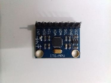
ADXL 335
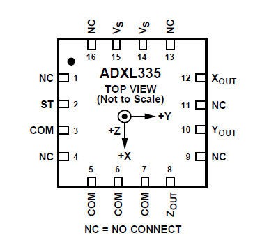 ADXL 335 circuit diagram
In our project the accelerometer is used to measure the acceleration or movements of the lower leg. Due to the limitations of technological boundaries and cost the 3 axis accelerometer is used. In the future a high precision accelerometer will be taken to consideration.
PARTICLE PHOTON:
The Photon is a microcontroller, which is a small, low-cost, low-power computer that can run a single application. The microcontroller runs the software and sends signals to the Photon .
Microcontrollers are particularly good at controlling things. They have a set of pins that are called GPIO (General Purpose Input and Output) pins, or I/O pins. They can be hooked to sensors or buttons to listen to the world, or they can be hooked to lights and motors to act upon the world. These microcontroller’s pins have been directly connected to the headers on the sides of the Photon so you can easily access them; specifically, the pins labeled D0 to D7 and A0 to A7 are hooked directly to the microcontroller’s GPIO pins.
The microcontroller can also communicate with other chips using common protocols like Serial (also called UART), SPI, or I2C (also called Wire). You can then make the Photon more powerful by connecting it to special-purpose chips like motor drivers or shift registers. Sometimes we’ll wrap up these chips on a Shield, an accessory to the Photon that makes it easy to extend the Photon.
The Photon also has a Wi-Fi module, which connects it to your local Wi-Fi network in the same way that your computer or smartphone might connect to a Wi-Fi network. The Photon is programmed to stay connected to the internet by default, so long as it can find and connect to a network.
When the Photon connects to the internet, it establishes a connection to the Particle Cloud. By connecting to the Cloud, the Photon becomes accessible from anywhere through a simple REST API. This API is designed to make it very easy to interface with the Photon through a web app or mobile app in a secure, private way, so that only you and those you trust can access the Photon.
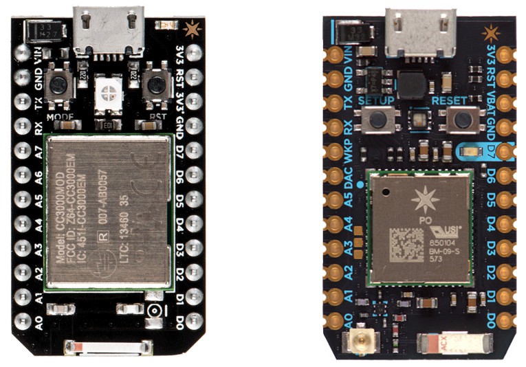
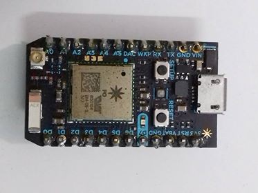
Particle Photon(both sides)
There are two buttons on the Photon: the RESET button (when holding the Photon with its USB-port to the top, it’s the button on the right) and the MODE button (on the left).
The RESET button will put the Photon in a hard reset, effectively depowering and repowering the microcontroller. This is a good way to restart the application that you’ve downloaded onto the Photon.
The MODE button serves three functions:
- Hold down the MODE button for 3 seconds to put the Photon into Smart Config mode to connect it to your local Wi-Fi network. The LED should start flashing blue.
- Hold down the MODE button for ten seconds to clear the Photon memory of Wi-Fi networks.
- Hold down the MODE button, tap once on the RESET button and wait for ten seconds** to do a Factory Reset, where the Photon is reprogrammed with the software that was installed on the Photon in the factory. The LED should turn white for three seconds and begin flashing quickly; when the LED switches to another color the Photon has been reset. This is useful if you encounter bugs with your firmware, or if you just want to get back to Tinker.
Particle Photon schematics
PINS:
The Photon has 24 pins that you can connect a circuit to. These pins are:
- VIN: To power the Photon off an unregulated power source with a voltage between 3.6V and 6V, or, if you’re powering the Photon over USB, this pin can be used as 5V V~OUT~ to power external components. In this case consider the current limitation imposed by your USB power source (e.g. max. 500mA for standard USB 2.0 ports). Avoid powering the Photon via USB and V~IN~ concurrently.
- 3V3: This pin will output a regulated 3.3V power rail that can be used to power any components outside the Photon. (Also, if you have your own 3.3V regulated power source, you can plug it in here to power the Photon).
- 3V3: This is a separate low-noise regulated 3.3V power rail designed for analog circuitry that may be susceptible to noise from the digital components. If you’re using any sensitive analog sensors, power them from 3V3 instead of from 3V3.
- !RST: You can reset the Photon (same as pressing the RESET button) by connecting this pin to GND.
- GND: These pins are your ground pins.
- D0 to D7: These are the bread and butter of the Particle Photon: 8 GPIO (General Purpose Input/Output) pins. They’re labeled “D” because they are “Digital” pins, meaning they can’t read the values of analog sensors. Some of these pins have additional peripherals (SPI, JTAG, etc.) available, keep reading to find out more.
- A0 to A7: These pins are 8 more GPIO pins, to bring the total count up to 16. These pins are just like D0 to D7, but they are “Analog” pins, which means they can read the values of analog sensors (technically speaking they have an ADC peripheral). As with the Digital pins, some of these pins have additional peripherals available.
- TX and RX: These pins are for communicating over Serial/UART. TX represents the transmitting pin, and RX represents the receiving pin.
- Then there are the PWM pins i.e Pulse Width Modulation pins
- These pins that have a timer peripheral. The Photon has 8 PWM pins: A0, A1, A4, A5, A6, A7, D0 and D1.
In our project the Particle Photon is used to obtain the sensor data and process them and send to the data to cloud/mobile app (ThinkSpeak Cloud) for easy visualization
Discussions
Become a Hackaday.io Member
Create an account to leave a comment. Already have an account? Log In.