 Nick Ames
The goal of the NoteOn project is to create a smart pen that is better than the ones currently on the market. It should be small, wireless, and self-contained.
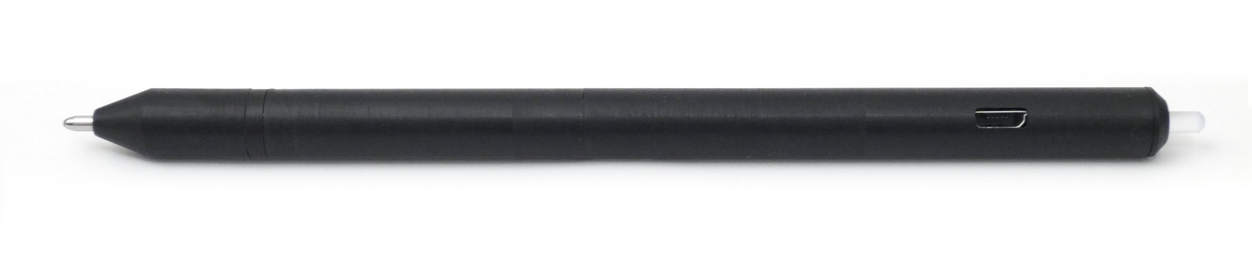
- Small: Most smart pens are 12mm or more in diameter. Normal writing implements generally range from 8-10mm. The NoteOn prototype is 10.0mm in diameter using an off-the-shelf battery and 2-layer board. The battery and PCB both limit the minimum size of the pen. With a custom battery and four layer PCB the diameter could probably be shrunk to 8mm.
- Wireless: NoteOn includes a Bluetooth 4.0 LE transceiver to transfer data wirelessly to mobile devices and computers. From there it can be uploaded to an Internet document service like Evernote or Google Drive.
- Self-Contained: This is the most important aspect of NoteOn. All currently available smartpens require either special paper or a base station that attaches to the page. NoteOn uses inertial measurement to track its motions without any external aids. It can be used with any notebook, sticky note, or napkin.
Electronics
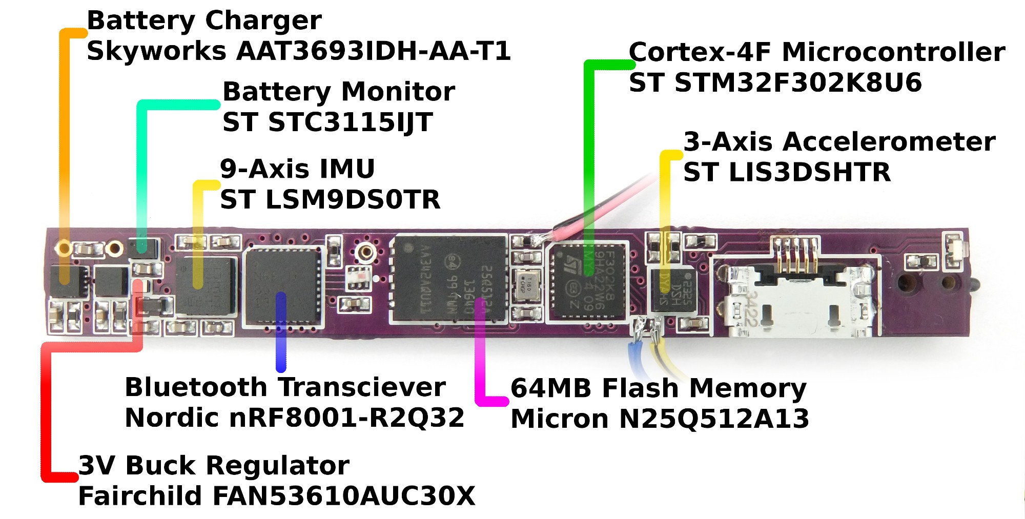
The heart of NoteOn is the ST LSM9DS0TR, a 9-axis MEMS inertial measurement unit. It contains a 3-axis accelerometer, gyroscope, and magnetometer. The data from the IMU is supplemented by the ST LIS3DSHTR, a 3-axis accelerometer. This auxiliary accelerometer is placed on the opposite end of the PCB from the IMU, and will be used to help locate the precise center of rotation movements (each accelerometer experiences a different rotation based on its distance from the pivot point).
The IMU and auxiliary accelerometer are connected to the microcontroller by the I2C bus. The microcontroller is an ST STM32F302K8U6. It contains an ARM Cortex-M4 core with a floating-point coprocessor, 64kB flash, and 16kB RAM. I chose this microcontroller because it included a USB interface in a small QFP-32 package. Most chips with USB interfaces are physically too wide for the NoteOn PCB.
For Bluetooth 4.0 connectivity, NoteOn uses the Nordic nRF8001. It connects to the microcontroller over SPI. Unlike many Bluetooth interfaces, it doesn't have an internal microcontroller that needs to be programmed, making it a good fit for a system that already has a powerful uC. The Bluetooth antenna bears mentioning: I don't have the skills or equipment to design an antenna matching network, so the output of the balun is fed directly into a piece of wire. The RF performance is undoubtedly horrible, but I think it will work well enough for the prototype.
Also on the SPI bus is the Micron N25Q512A13GF840E, a 512Mbit (64Mbyte) NOR flash memory. I would have liked to for NoteOn to have more memory, but most flash chips are too wide.
Power is provided by a GoldPeak GP0836L17 170mAh lithium battery. (This battery is not available from GoldPeak, but clones of it are marketed as replacements for the Sony MH-100 headset. See BatteryBob #201747 and various sellers on Ebay.) This was the smallest diameter lithium-ion battery I could find. Although NiMh batteries are more commonly available in these small sizes, their low voltage makes the power supply design difficult.
The battery is charged from USB power by a Skyworks AAT3693IDH-AA-T1. Power is provided to the system through a single 3.0V rail generated by a Fairchild FAN53610AUC30X, a 3Mhz buck regulator in an exceptionally small 6-CSP package. A dual diode powers the regulator from the USB when it is available. (My first iteration of the design used a fully integrated diode, charger, and regulator IC. Unexpectedly, discrete parts took up less space.)
The battery voltage is monitored by an ST STC3115IJT Li-ion gas gauge. It connects to the microcontroller over the I2C bus.
No provision is made to switch off the power rail when the pen is in sleep mode, so sleep mode is achieved by putting all the ICs into their low-power states. This is something I'd like to address in the next design revision.
A single momentary switch and blue LED are the pen's user interface. The switch turns the pen on and off, and the LED lights up when the pen is on. Another switch in the tip of the pen detects when the ball point is pressed to paper.
EagleCAD was used to route the 2-layer PCB. Space for components and traces was very limited, and it took several tries before I could route the whole board. OSHPark was used to manufacture the PCBs.
A few compromises were made during routing: I put traces underneath the IMU and aux. accelerometer, something their datasheets recommend against. I also omitted the central pads underneath the memory and microcontroller. These aren't electrically necessary, but they increase mechanical strength.
Both prototypes were assembled by toaster-oven reflow. I used a .003" Kapton stencil from OSHStencils to lay down solder paste, then placed the parts by hand. Although I used lead-free solder, I didn't have any joint quality issues.
Case
The NoteOn case is made of seven parts machined from black polycarbonate, clear acrylic, and delrin. All the parts were machined on my Taig lathe. A milling attachment and simple fixture were used to cut steps, slots, and wire holes.
The case has three compartments, which hold the ink cartridge, battery, and PCB.
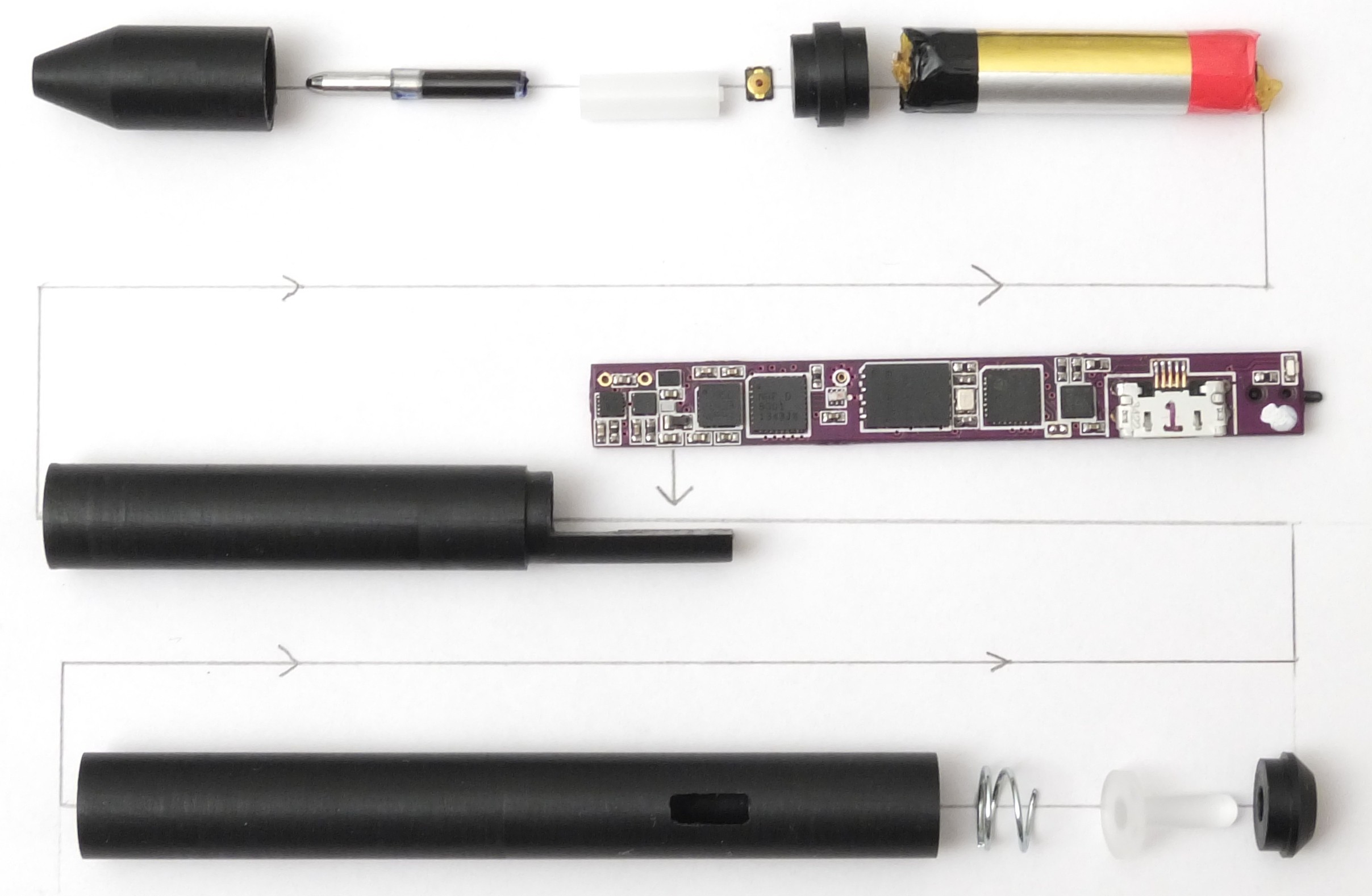
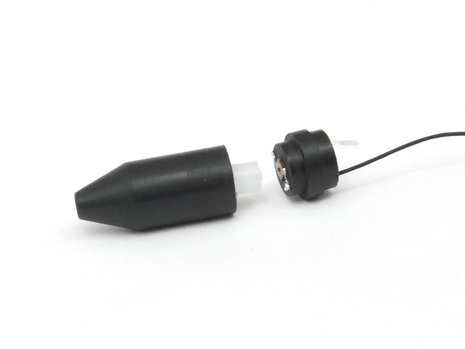
A ball-point ink cartridge from a disposable pen was cut to size and inserted into a delrin sleeve. (Delrin was chosen for its small coefficient of friction.) When the pen is pressed to a page, the sleeve slides a small distance and actuates a tactile switch.
One terminal of the switch connects directly to the battery (-) terminal; the other goes to the PCB.
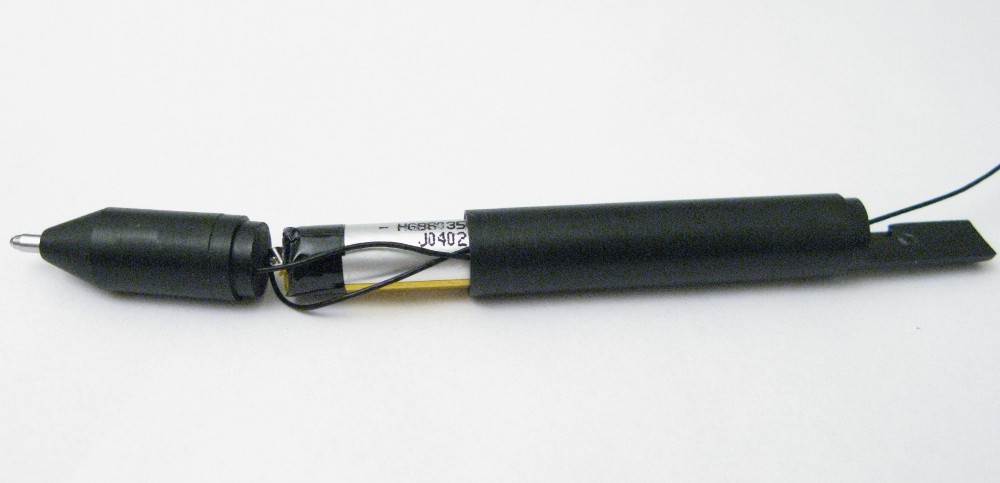
A shelf projects from the battery shell. Above it, a hole allows the battery (+), battery (-), and tip switch wires to come through. The PCB is adhered to the shelf with super glue.

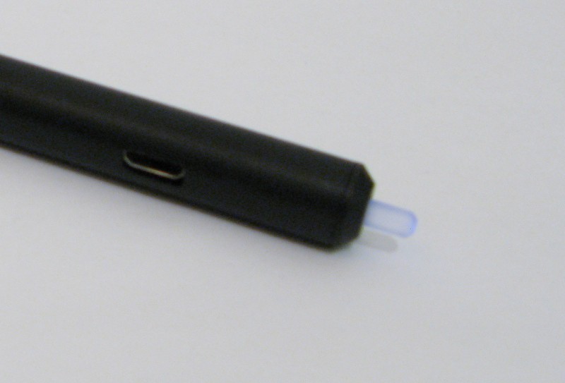
The PCB shell goes over the PCB. It includes a slot for the USB port. On the free end of the PCB a weak spring supports the clear acrylic button. (The status LED is supposed to make the button light up, but it isn't bright enough. This will be addressed in the next design revision.) Finally, the endcap prevents the button from falling out.
Firmware
Getting a working open-source toolchain set up was a bit challenging. After some trial and error, I settled on using gcc-arm-embedded for the compiler and utilities, with chip support provided by libopencm3. I was not able to the libraries provided by ST, the manufacturer, because they come with a very restrictive license that is not compatible with the openness goals of the Hackaday Prize.
Firmware is downloaded to the chip using a patched version of stm32flash with the chip's on-board serial bootloader. (Dfu-util may also work, but I haven't tried it.)
Note: The firmware is still under heavy development, so the following details may not be valid in the future.
The firmware is structured around a single main thread interrupted for short durations by device drivers. Some of these drivers are for on-chip peripherals (such as the SPI and I2C interfaces) and some are for external peripherals (like the IMU and battery gas gauge). To keep interruptions short, DMA is used wherever possible and drivers are structured to never wait or stall.
Data from the IMU and auxilliary accelerometer is fetched at a 100Hz rate. The accelerometers and gyroscope produce data at 1600Hz and 760Hz respectively, so data is stored in their internal FIFOs between fetches. (The magnetometer produces data at 100Hz and does not have a FIFO, so its value is simply queried at every fetch.) The IMU driver maintains two buffers to allow the main task to access the previously fetched data as new data is coming in.
Thanks for reading. Please let me know in the comments if there's anything I haven't properly explained.