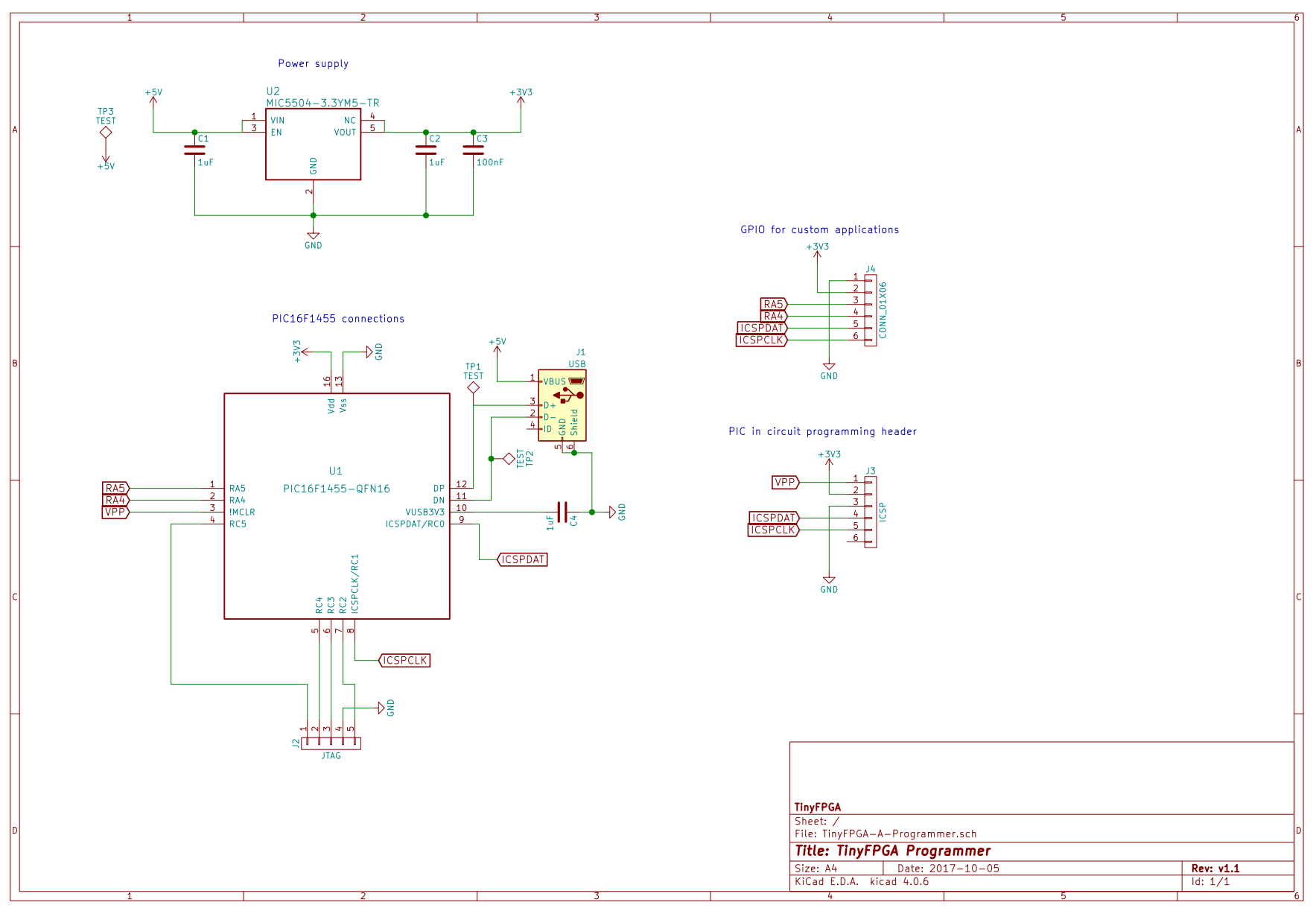
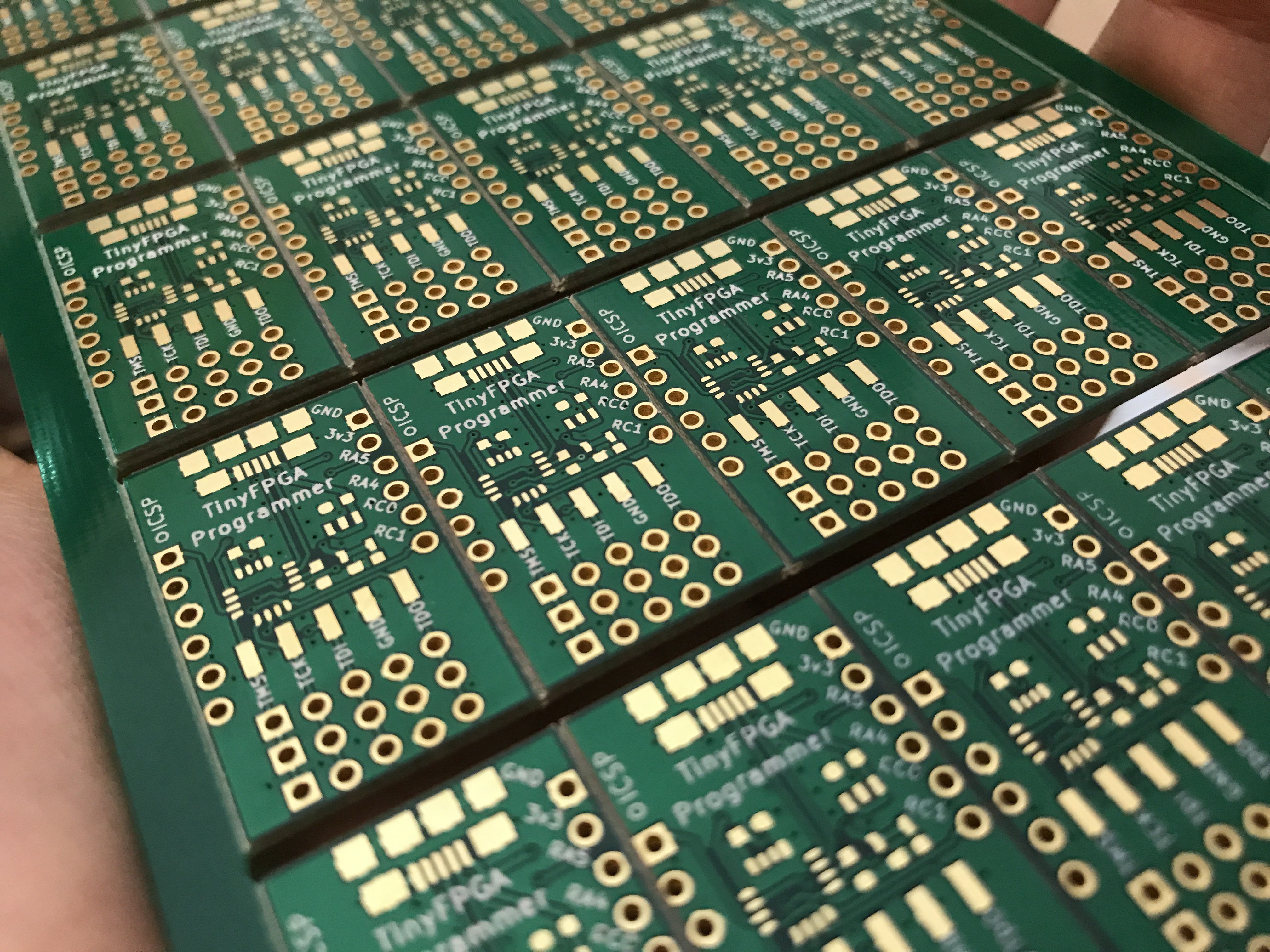
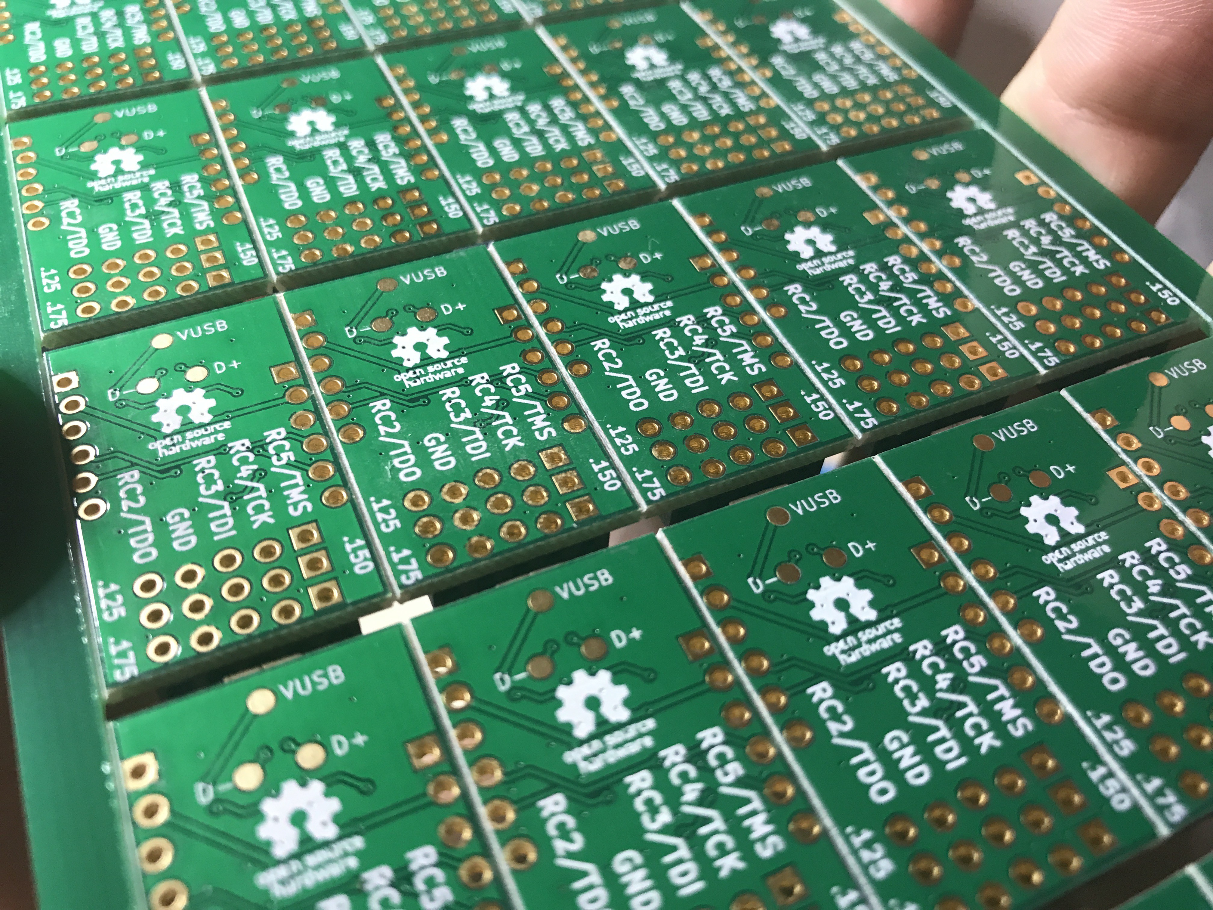
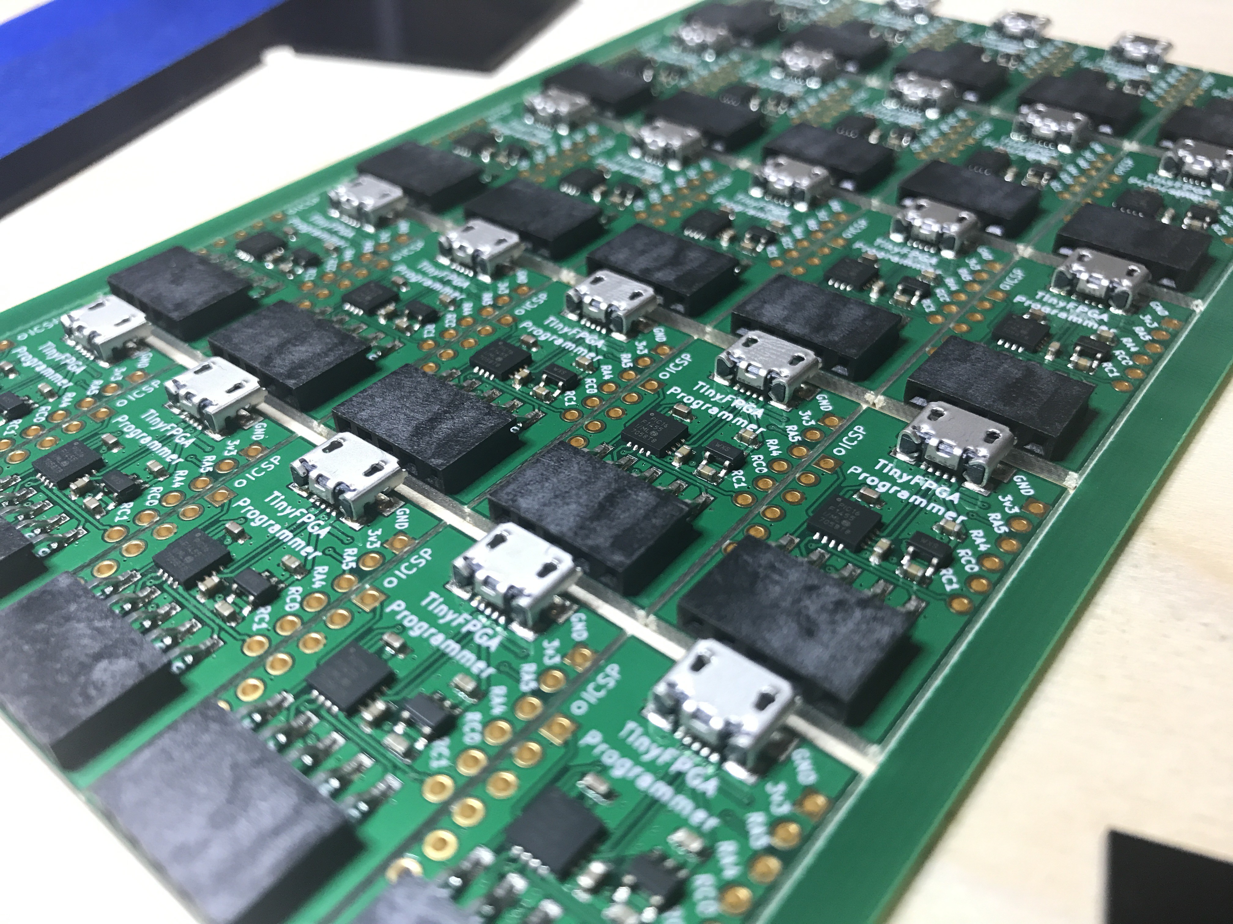
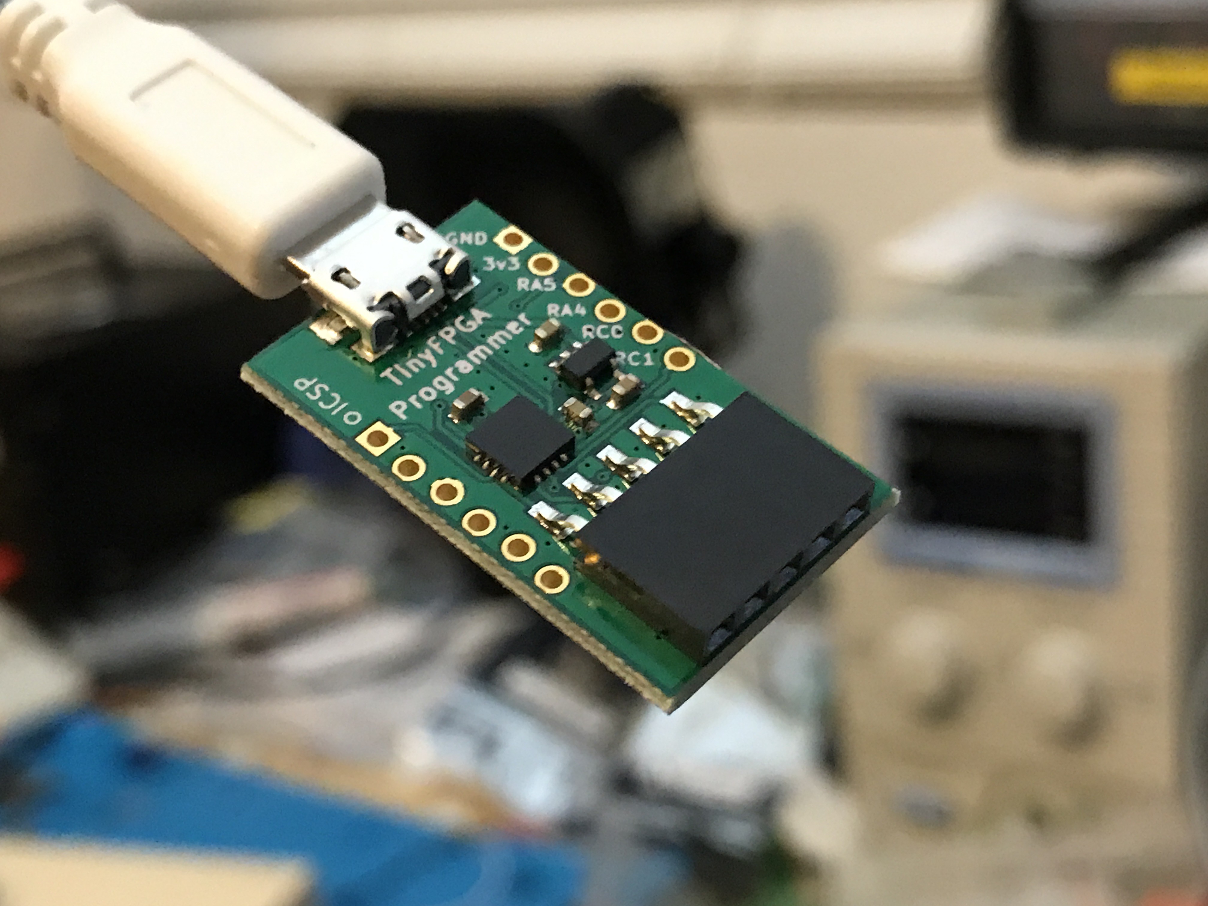
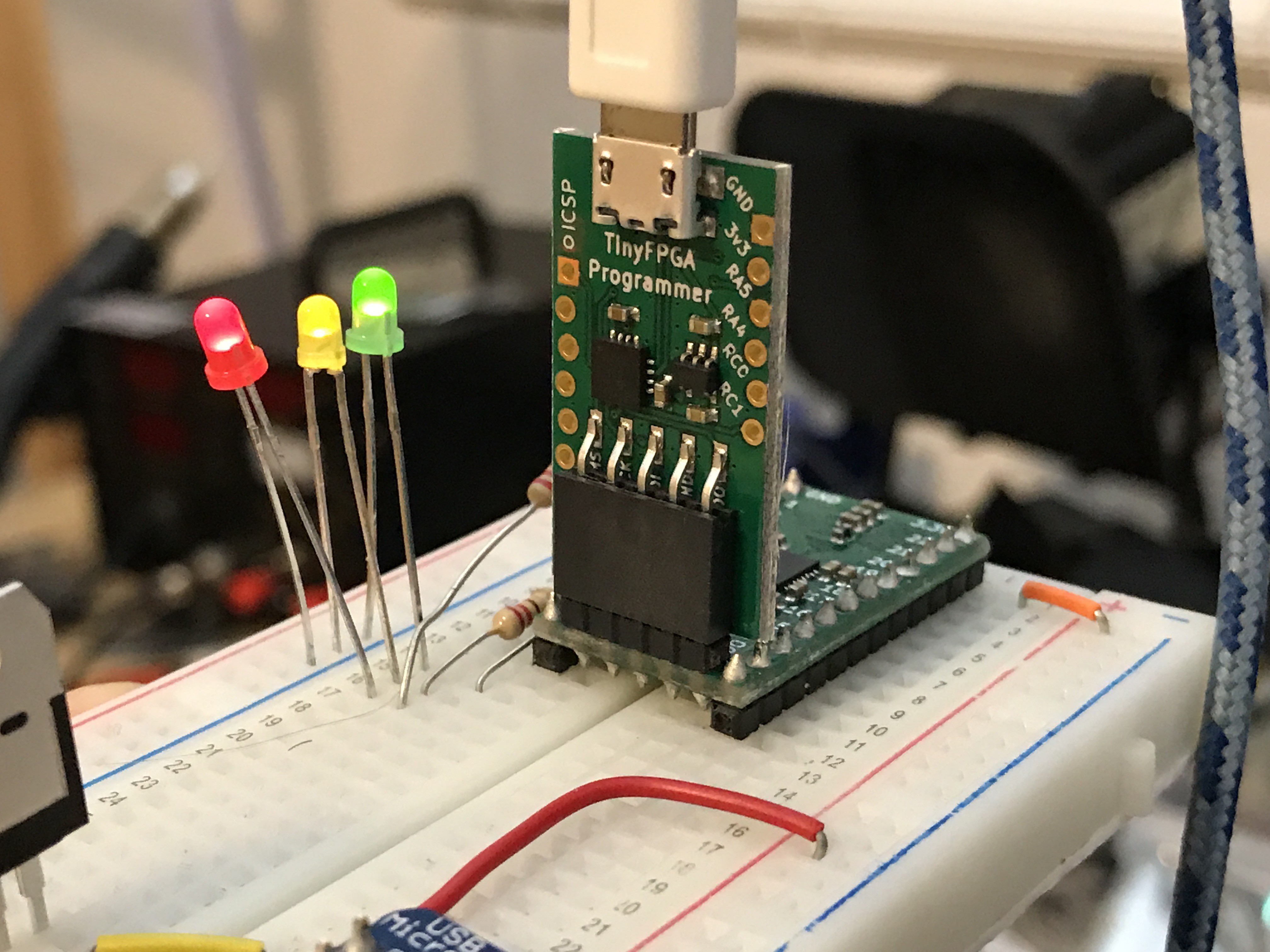
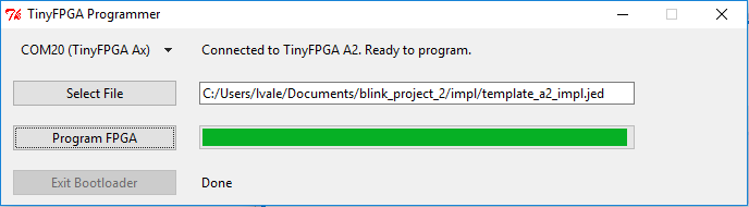
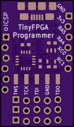
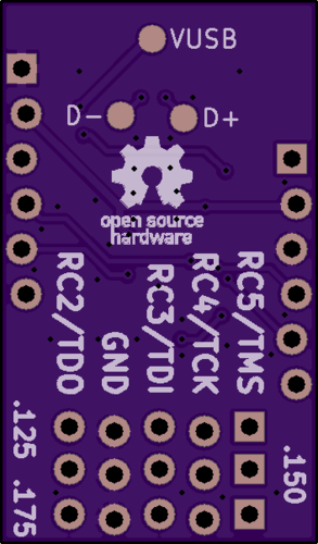
• Schematic PDF Available

    Luke Valenty10/07/2017 at 03:16 2 comments

    I've finally gone over the schematics of all my projects and organized them a little bit so they are nice and easy to follow.  For people that don't have KiCad installed, making the schematics available in PDF form is much more convenient and easy to share for quick reference.

    You can view the PDF directly on GitHub: https://github.com/tinyfpga/TinyFPGA-A-Programmer/blob/master/board/TinyFPGA-A-Programmer.pdf, or you can take a look at the image included below.

    I've also started a new Hackaday.io project, #The Hobbyist's Guide to FPGAs.  I'll be posting articles, tutorials, and hands on labs using the TinyFPGA boards as project logs.  If this sounds interesting to you then follow the project to be updated when new content is posted.

  • For Sale!

    Luke Valenty09/27/2017 at 03:08 0 comments

    The TinyFPGA Programmer boards are now for sale!

    You can purchase them for $9 at the TinyFPGA Store.   Unfortunately I'm unable to login to Tindie to update my Tindie store, but once that has been resolved they will be listed there as well.

    For instructions on programming #TinyFPGA A-Series boards with the new programmer have a look at the updated TinyFPGA A-Series Guide.

    Enjoy!

  • Production Update

    Luke Valenty09/20/2017 at 09:00 0 comments

    I just finished assembling and reflowing 75 more TinyFPGA Programmer boards.  I have about 100 boards ready to sell.  It took a bit longer to assemble than I had anticipated.  I'll probably go back to having them assembled by my PCB house if I need a larger batch.  

    I have a bug with the programmer application on MacOS.  I'm working on a fix.  Once it's verified I'll be making an official release of the programmer application and putting the TinyFPGA Programmer boards for sale on Tindie and my own store.

    Soon!

  • PCBs Delivered and Assembled

    Luke Valenty09/13/2017 at 07:00 0 comments

    The PCBs arrived from the fab today.  They look excellent.  I set them up for 25 boards per panel and got a stainless steel solder paste stencil along with them.  

    Over the weekend I ordered 25 PIC16F1455 microcontrollers so I could assemble some boards ahead of the main order of PICs from Microchip.  Programming 25 boards manually isn't too bad, especially after going through the work of assembling them.

    Assembly and reflow went well.  My reflow oven might be running a little hot.  I noticed the silkscreen is slightly darker than the bare PCBs still in the packaging.  Besides that the assembled boards look and work just as well as the boards I've gotten pre-assembled.   

    I broke apart the panel and tried programming one of the boards without soldering pins onto the ICSP header.  It didn't work.  So I figured it just wasn't making a good enough connection and I soldered on a set of pins.  It still didn't work.  I was pretty worried at this point, but the basic design of the PCB was the same, and all of the solder joints looked great.  To try and isolate the problem I attached the PICkit3 programmer to one of my prototype boards.  It didn't work.  Whew.  It wasn't the new boards.  Finally I followed the tried and true method of unplugging and then replugging the PICkit3 programmer and trying again.  Success!

    I programmed and tested about 8 boards so far.  All programmed successfully and the TinyFPGA programmer GUI has no problem recognizing the hardware and communicating with a #TinyFPGA A-Series board.

    The breadboard in the picture was my basic testbench for developing the firmware for the PIC.  I had connected my logic analyzer to the JTAG pins to view and debug the JTAG programming flow as well as performance issues.  

    All of my boards are open source and open hardware, but this is the first board to actually contain the logo.

    I should be placing the boards for sale on @Tindie by next week.  I only have 25 boards until the pre-programmed PICs come in.  Speaking of, I just received an email from @Microchip Technology that the 200 PIC16F1455 chips have been programmed and shipped.  At that point I'll assemble them one panel at a time.  I'm still working on exact pricing, but I can confirm they will be available with the right-angle header soldered on for less than $10.  I could also sell bare PCBs and boards without the right-angle header for a discount.

    I'm really excited to bring this programmer to market.  It's significantly cheaper than the alternatives and will make #TinyFPGA A-Series even more accessible.  Once this is for sale I have more open TinyFPGA projects and products in the works.

    Stay tuned.

  • GUI Support Complete

    Luke Valenty09/11/2017 at 06:19 0 comments

    Support for the #TinyFPGA A-Series is complete in the TinyFPGA Programmer Application.  

    Now when you launch the GUI the port selector will also tell you whether it is an A-series board or a B-series board.  As TinyFPGA boards are connected or disconnected, the list will automatically update.

    While a particular port is selected for either type of TinyFPGA board the programmer will continuously test the connection to the board.  If the programmer is disconnected from the board, the board lost power, or the USB cable was disconnected, it will let you know.

    Just as the #TinyFPGA B-Series boards will have a progress bar for programming, the #TinyFPGA A-Series do as well.  As the configuration flash is erased, written, and verified, you will know at every step of the way.

    Programming speed is just as fast as it has been during development of the tinyfpgaa.py Python driver.  This means small images take about 3 seconds and large images will take up to 12 seconds.  This is faster than the Diamond Programmer and Lattice Download Cable.

    Delivery of the production PCBs is estimated to be September 12th.  I have a few PIC16F1455 chips I may use to assemble some boards and give them a spin.

  • Production PCB Fabrication Complete

    Luke Valenty09/09/2017 at 21:43 0 comments

    Looks like the production PCBs have completed fabrication.  Should be on track to receive them early next week.  Delivery for the pre-programmed PIC15F1455 micros is set for one week from today.  This means I most likely won't be able to sell any TinyFPGA Programmer boards for about a week and a half.

    In the meantime I've been reorganizing the FPGA programming/configuration Python code around the git repos and consolidated the GUI in its own repo.  With this change the only programmer application you will need to use is the TinyFPGA Programmer Application.  It automatically recognizes TinyFPGA boards and programmers when they are connected and gives immediate feedback on connectivity and configuration status.

    If all goes to plan the TinyFPGA Programmer Application will have a new release tomorrow that can program both #TinyFPGA A-Series and #TinyFPGA B-Series boards.

  • Bug Squashed

    Luke Valenty09/08/2017 at 06:16 2 comments

    Yesterday I was able to root-cause the bug where only '0' data would be returned from the PIC16F1455 over USB to the Python module.  This turned out to be an interesting bug.

    The bug appeared after I made some seemingly unrelated changes to the code.  I could not figure out why the data returned was always null.  I traced the firmware's execution in the debugger and followed the return data through the various buffers and it was always correct.  

    Looking through the PIC16F1455 datasheet I was reminded of the special dual-port RAM for the USB controller.  Looking at the buffers in the USB stack source code from Microchip there was no annotations to keep them in this special dual-port RAM location.  Upon further reading of the spec I found that the USB controller can only read data from the dual-port RAM.

    Checking the map file with the compiled addresses of all the variables in the firmware I find that the transmit buffer is not within the dual-port RAM. Bingo.  It turns out the firmware worked before because I was lucky and the buffers happened to be allocated in the right location.  However, once some extra variables and data structures were added, the compilers allocation algorithm happened to place the USB buffers outside the dual-port RAM.

    The solution seemed simple; tell the compiler to assign the USB buffers within this dual-port RAM address range.  It turned out not to be so.  Even though I could tell the compiler where to put the buffers, I would still get corruption on the transfers.  As I dug further into the USB stack I started to replace sections with my own versions of the CDC device class transmit and receive path.  This led to a much better understanding of the USB hardware in the PIC as well as fully functional firmware.

    I'm not quite ready to order the pre-programmed PICs just yet.  Will need some more testing to gain confidence.  On a related note, the production PCBs are about half-way finished being fabricated.  They could be delivered to me as soon as early next week.

  • Production PCBs Being Fabricated

    Luke Valenty09/06/2017 at 14:53 0 comments

    Production PCBs are being fabricated.  Should take about  a week to finish and get delivered.  While that's going on I've ordered all the necessary parts for a first assembly batch except for the PIC microcontroller.  I believe it will take me too long to develop a robust programming sequence for the PIC on a pogo pin test bed so I've opted to have Microchip pre-program the PICs for me.  As for assembly, I've had the #TinyFPGA A-Series and #TinyFPGA B-Series boards assembled in a factory, but I am planning on assembling the #TinyFPGA Programmer boards myself.  They have very few parts and nothing tricky.  This will help keep the final price of the boards low.

    I have one more bug I'm aware of with transmitting USB data.  At some point along the way of my optimizations the USB IN data started getting corrupted...it's always '0'.  I'm going over the CDC code generated by MPLAB as well as the PIC16F1455 datasheet to understand what's going on.  Once that's fixed I'll be able to order the pre-programmed PICs.

  • Updated PCB Design

    Luke Valenty09/05/2017 at 04:45 1 comment

    I've made a few updates to the PCB design.

    1. I added extra staggered JTAG headers.  Each of the three rows have pin holes staggered by slightly different amounts.  This will allow you to find just the right fit if you chose not to solder a socket.
    2. I added SMD pads for a surface-mount right-angle socket for JTAG.  When I produce the boards this will make it easier for me to sell some with a right-angle socket soldered on.
    3. I broke-out all the pins from the PIC16F1455 microcontroller, as well as the 3.3 volts from the LDO regulator.  This has a couple benefits:
      1. Along with the ICSP header, you can use the board like a generic PIC breakout board
      2. You can use the 3.3v output to power your #TinyFPGA A-Series project

    The latest PCB design has been uploaded to GitHub as well as OSH Park.

    Sending these boards off to a small production run.  By the time I get them back I should have fixed that last few lingering firmware issues and should be ready to list them on my Tindie store.

  • New Command Set

    Luke Valenty09/04/2017 at 21:32 0 comments

    In the last log I wrote about how much faster the new firmware and Python library is.  Now I want to talk a little bit about the new commands that enable this performance improvement.

    TinyFPGA Programmer Firmware Command EncodingTinyFPGA Programmer Firmware Command Encoding

    There were three original commands for driving the programmer: CONFIG_IO, SET, SET_GET.  These commands allow you to configure individual GPIO pins for INPUT or OUTPUT, set pin values, and get pin values.  They are enough to bit-bang slow enough protocols, but not very fast.  

    To enable the faster speeds in the latest firmware, six new commands were added:

    SHIFT

    This shifts many bytes of data at a time serially through the GPIO pins.  The shift operation is highly configurable: it can output data, input data, check data with a mask, and even  consume or produce no data at all if configured to do so.  The firmware supports a total of 8 programmable SHIFT configurations that allow many aspects of the SHIFT command to be configured.

    CONFIG_SIE

    SIE stands for Serial Interface Engine.  CONFIG_SIE allows you to program each of the 8 serial interface engine configurations.  When a SHIFT command is sent, it specifies the index of the SIE configuration to use.

    LOOP and END_LOOP

    A total of 60 bytes worth of commands can be repeated up to (2^16 - 1) times or until a SHIFT check data operation within the loop matches.  This capability is used for JTAG programming to poll the FPGA's busy status bit while waiting for a flash erase or write operation to complete.  Loops must be terminated with an END_LOOP command.  If the loop terminates before a successful match, a failure status code will be sent to the host computer.

    GET_STATUS and CLEAR_STATUS

    Results of SHIFT with check data, and LOOPs are only returned if there is a failure, and only if a failure has not previously been reported.  Before a bitstream is programmed to a TinyFPGA board, the CLEAR_STATUS command is sent.  At the very end of the entire programming procedure, the GET_STATUS command is sent.  If there is an error, the error status will be sent at the time the error occurred as well as when the GET_STATUS command is executed.  If there is no error, then a successful status will be sent when the GET_STATUS command is executed.