 Luke Valenty
I've made a few updates to the PCB design.
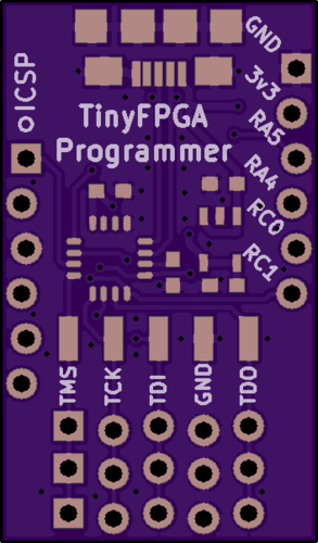
- I added extra staggered JTAG headers. Each of the three rows have pin holes staggered by slightly different amounts. This will allow you to find just the right fit if you chose not to solder a socket.
- I added SMD pads for a surface-mount right-angle socket for JTAG. When I produce the boards this will make it easier for me to sell some with a right-angle socket soldered on.
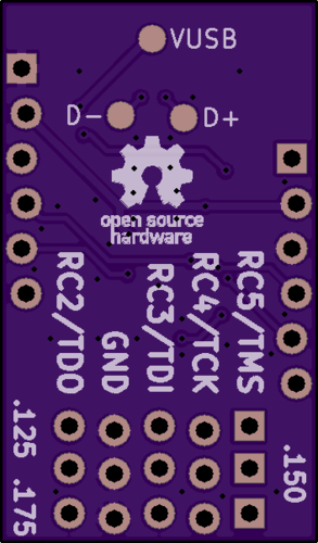
- I broke-out all the pins from the PIC16F1455 microcontroller, as well as the 3.3 volts from the LDO regulator. This has a couple benefits:
- Along with the ICSP header, you can use the board like a generic PIC breakout board
- You can use the 3.3v output to power your #TinyFPGA A-Series project
The latest PCB design has been uploaded to GitHub as well as OSH Park.
Sending these boards off to a small production run. By the time I get them back I should have fixed that last few lingering firmware issues and should be ready to list them on my Tindie store.
Discussions
Become a Hackaday.io Member
Create an account to leave a comment. Already have an account? Log In.
Exciting!
Are you sure? yes | no