 Luke Valenty
At last, after some long evenings working through various issues I've rewritten large portions of the TinyFPGA Programmer firmware and Python module to be much, much faster.
How fast? For a small design it can erase, program, and verify flash in 3 seconds. For a large design utilizing the entire FPGA it takes about 10 seconds. For comparison, the official Diamond Programmer and Lattice Download Cable takes about 15 seconds for the MachXO2 1200 FPGAs.
Fast bitstream program time matters because it means you can verify your changes on the real FPGA faster. Fast programming of flash means you don't have to worry about a power glitch or power loss to the board wiping out the SRAM configuration. The latest configuration bitstream will always be loaded.
How did I enable such a large improvement in speed? It comes down to recognizing the inefficiencies in the system and implementing optimizations that work around them:
Bitbanging the PIC's GPIOs over USB is slow
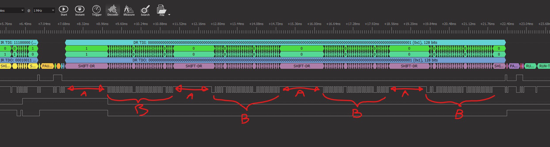
It increases the amount of USB traffic the PIC needs to process and doesn't allow for a fast inner loop. Below is a waveform of the JTAG pins while the TinyFPGA Programmer is writing the #TinyFPGA A-Series FPGA's flash. The sections marked A are times when the firmware was processing incoming and outgoing USB packets. The sections marked B are times when the firmware was actively driving the JTAG pins, but was only able to achieve about 15KHz. These two inefficiencies add up to a lot of wasted time.
The solution is to add commands to shift many bytes worth of data all at once. This reduces the overall amount of USB traffic the PIC needs to process and allows for a very tight inner loop.
Synchronous communication over USB is slow
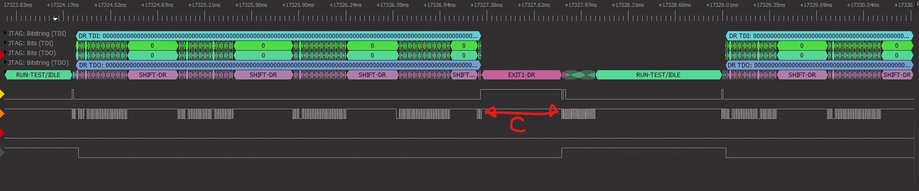
Writing a command to the PIC over USB, then waiting for a response takes at least a few milliseconds of time. This happened every time the programmer needed to wait for a status bit to clear or verify data from the FPGA. The section marked C in the waveform below shows where the Python application was waiting for a response from the PIC before it would send new commands.
There are multiple optimizations here:
- First optimization is to enable polling to occur completely within the PIC microcontroller. Now the next programmer command can be executed immediately after the polling successfully finishes.
- Second optimization is to allow the PIC microcontroller to verify the data itself without having to send it back to the Python application.
- Third optimization is to send information to the host only if absolutely required. If a POLL command or SHIFT command fails due to a mismatch, a status packet is sent back. Otherwise the status is not sent to the host Python application until it is requested at the end of the programming command stream.
Blocking writes are slow
Every time the Python programmer module writes to the serial port it appears to be a blocking operation and the process would get context-switched. This adds a few milliseconds while the programmer is idle waiting for commands to process.
To hide this latency I increased the buffer to 256 bytes to enable several packets to be queued up to transmit at once. This seems to be enough to keep the programmer hardware fed with commands while the Python application is blocked.
Default Lattice SVF files are inefficient
Lattice SVF files contain large delays within polling loops, and program unused rows unnecessarily.
Now that I understand the programming protocol very well, I wrote a custom JEDEC file parser that determines exactly what JTAG commands to issue. I was able to reduce the wait time between status polls to speed up polling. I was also able to program only the rows that have non-zero data.
Compiler optimizations
A final optimization performed I'm not too happy about. My firmware ran up against the program flash size of the PIC16F1455. I had to get a demo license of the XC8 PRO compiler from Microchip in order to optimize the program flash size. This also had the side-effect of speeding up the serial data shift loops.
The resulting waveform
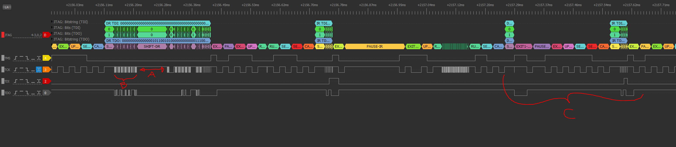
Time A: The firmware still pauses to process incoming packets, but these occur less often. Additionally the Python application sends more data per serial write operation so there are always commands for the programmer firmware to execute. These gaps tend to be 100-200 microseconds in length now compared to 1-5 milliseconds before.
Time B: Shifting serial data is now much faster. Brute-force bitbanging over USB would operate at about 15KHz, but now the optimized data shifting routines operate at about 1MHz.
Time C: Polling occurs completely within the firmware now, so the next command is executed immediately after the status bit is cleared.
All of these optimizations added up mean that a lowly PIC16F1455 with only Full-Speed 12MBit/second USB can erase, program, and verify the MachXO2 FPGAs at least as fast, or faster than the official hardware and tools from Lattice. I plan on selling these on my Tindie store for less than $10.
The latest code is committed to GitHub. There are a couple of bugs to fix and more testing to perform, and I need to integrate this into the TinyFPGA Programmer GUI, but I am very happy with current progress.
Discussions
Become a Hackaday.io Member
Create an account to leave a comment. Already have an account? Log In.