MakerVisioneer
-
Obstacle Avoidance with the prototype
10/21/2017 at 07:37 • 0 commentsThe video clip shows the sonar sensor detects an object within a distance of 6ft and the feedback signal comes from the vibration motor on both sides of the glasses. As the object gets closer, the vibration frequency gets higher.
-
Neural Net Journey
10/21/2017 at 05:18 • 0 commentsThe Pi Zero was a real challenge to use for neural net inference. Neural nets take special advantage of parallel processing, which the Zero's ARMv6 CPU just doesn't do (unlike its ARMv7 brother, Pi3). Early results were abysmally slow compared to the Pi 3 and early on I craved a multi-cored CPU or better yet access to the Pi's GPU (I found some claims of access, but nothing more than very low level operation code).
For network selection, after trying many choices, I landed on Tiny YOLO for Darknet https://pjreddie.com/darknet/yolo/, due to its small size, easy of use and SSD capability which locates the object in the frame. MobileNet SSD was my first choice https://github.com/chuanqi305/MobileNet-SSD, but I had trouble with the Caffe implementation and ran out of time to try Tensorflow. The Movidius USB stick on Caffe was available to me, but its proprietary nature made want to do my best on the Pi for this project and keep it more "Open". In recent days, Movidius has found support by Tensorflow and even an unsupported version of YOLO https://github.com/gudovskiy/yoloNCS. Look for Movidius X to by a key player for mobile nets soon!
After deciding on Tiny YOLO, I still needed more improvements to speed. I found an amazing CPU optimizer for Darknet https://github.com/digitalbrain79/darknet-nnpack, which vastly improved neural net speed.
The network was still too slow at this point, so I began tweaking the Tiny YOLO layers to customize an even smaller version at the cost of accuracy. I found this article helpful http://guanghan.info/blog/en/my-works/yolo-cpu-running-time-reduction-basic-knowledge-and-strategies/
Another challenge was competition from video processing from the camera. I found a nice script that led me to use picamera in a way that keeps the images in a GPU-based stream http://www.tech-g.com/2015/07/03/raspberry-pi-camera-quick-guide/. This was far faster than raspistill and kept its hands off the CPU, allowing it to play nice with the neural net computations (which obviously throttle). I had wanted to access the stream directly with OpenCV for real-time processing (very efficient!), but it didn't end up playing nice with the Pi's other friend either.
For video processing, I decided to drop small picamera images (320x240) out of the stream and into a storage queue, every 300 ms, whereby the neural net could pick it up at its leisure, since it was much slower than what the cam could throw at it. From there, the neural net would process the image for detection in about 1 FPS.
This first clip isn't a live feed from the picamera, since displaying video output AND computation at the same time would wreck the FPS. The frame rate of the clip reflects the slower framerate that the Pi itself can process the images for detection.
This next clip is at night. You can tell the picamera image is grainier, darker (I lightened it for viewing) and there are shots further away. This was much more challenging to detect accurately. Notice where it occasionally mis-identifies the arrow on the sign as a button. This is due to the fact that most of the training images had arrows on the buttons themselves.
Lastly, I needed to use the bounding box coordinates in a way that lets the user know if the button is to the left or right. I ended up compiling the calculation into the original image.c file of Darknet https://github.com/pjreddie/darknet/blob/master/src/image.c. The calculation determines whether the box is left\right\center of the frame, then returns a text character "L", "R" or "C" along with the detection class (button) itself, allowing the Python script outside to take that output and activate the vibration motors (left, right or both).
Please note: Although the neural net works for pedestrian buttons (by far the most varied and tiny object on the list), I ran out of time to train the walk signal and crosswalk detection. Those objects (walk signal and truncated domes http://etc.usf.edu/clippix/picture/truncated-domes.html) are larger and more consistent than the buttons. They will be much simpler to detect and its really just a matter of throwing the bounded images into the model and allowing them to train. Customizing a neural net to run on a Pi Zero CPU, at any decent speed, is a major achievement for this team and we're very proud to come as far as we did, since July, when we first formed and began this work from scratch.
-
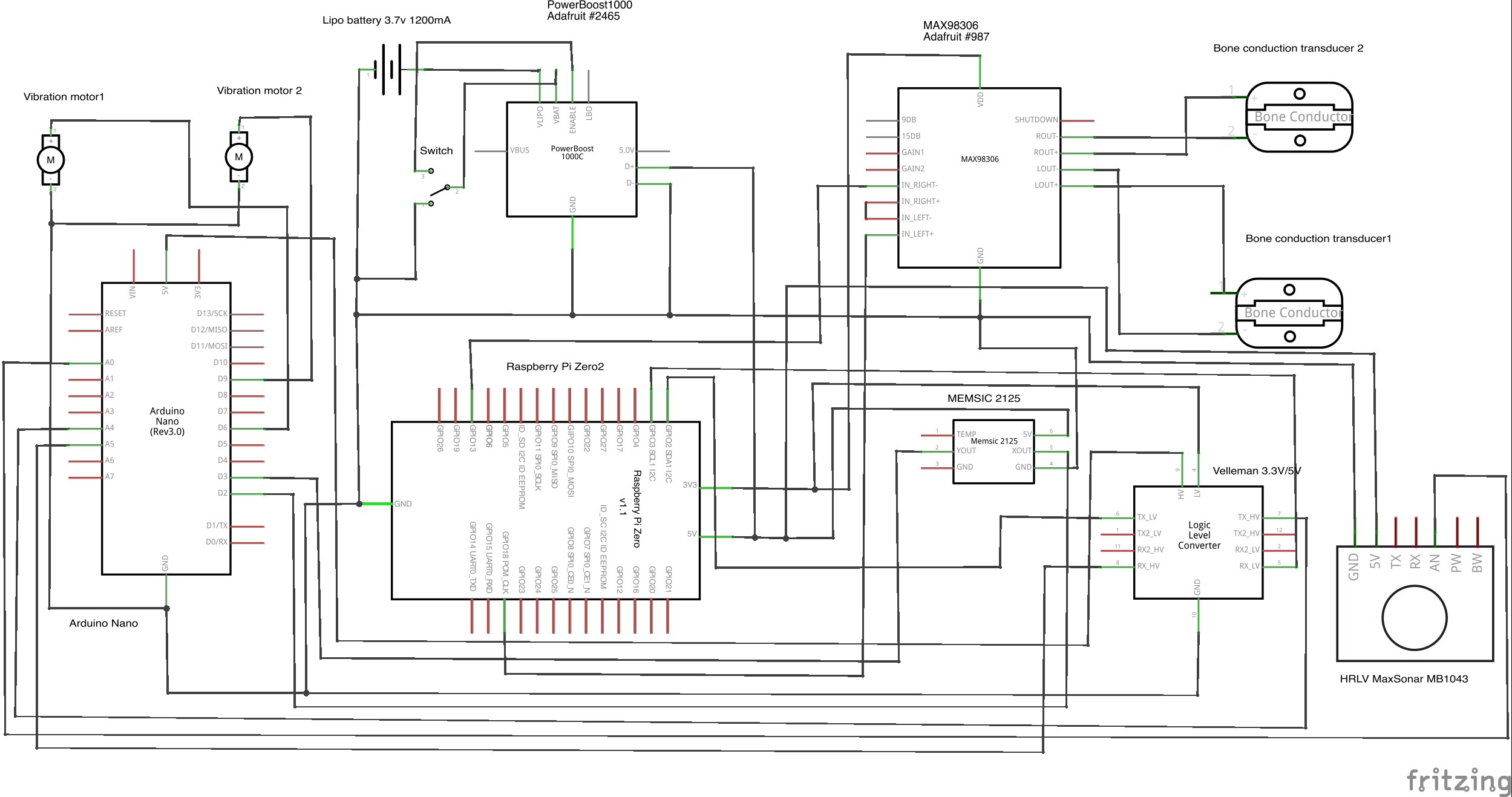
Schematic for Visioneer V2.0
10/15/2017 at 17:35 • 0 commentsIn Visioneer V2.0, we've added vibration motors to better alert deaf blind users in both obstacle avoidance and traffic detection. Arduino Nano is also included to offload Raspberry Pi Zero for the signals from the two sensors and the 3.3V/5V logic level converter is also added to step down 5V on Arduino and step up 3.3V on Pi Zero at the same time and both Arduino and Raspberry have a connection.
![]()
-
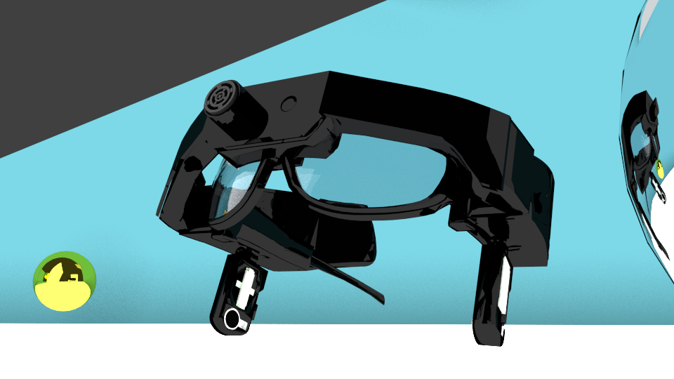
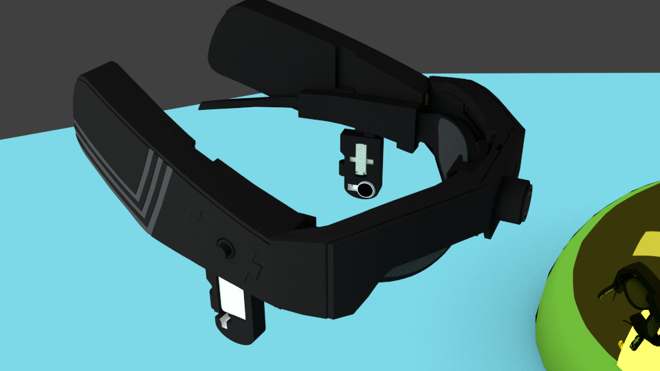
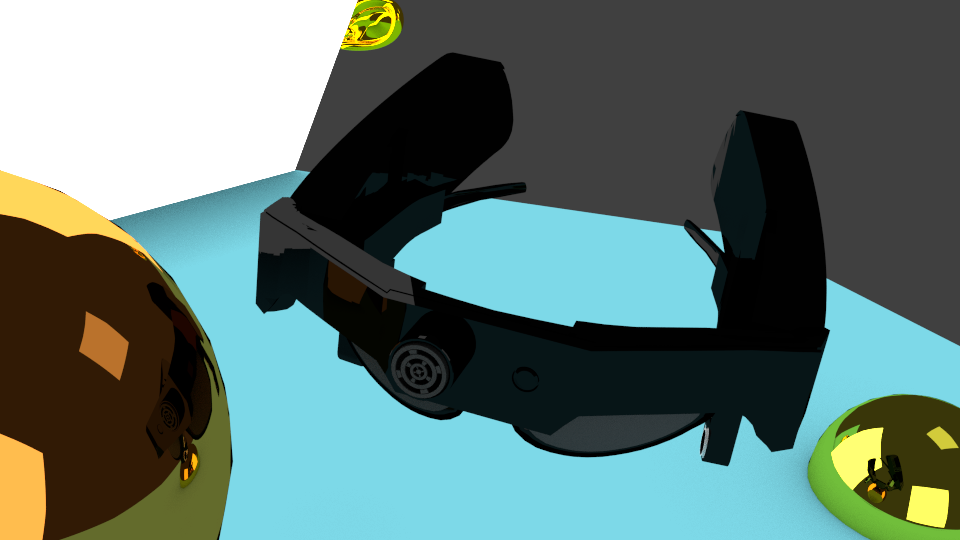
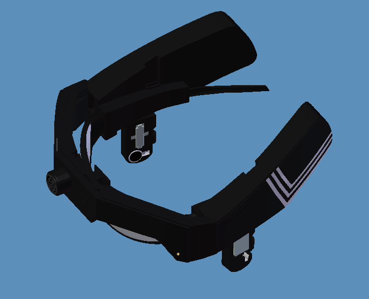
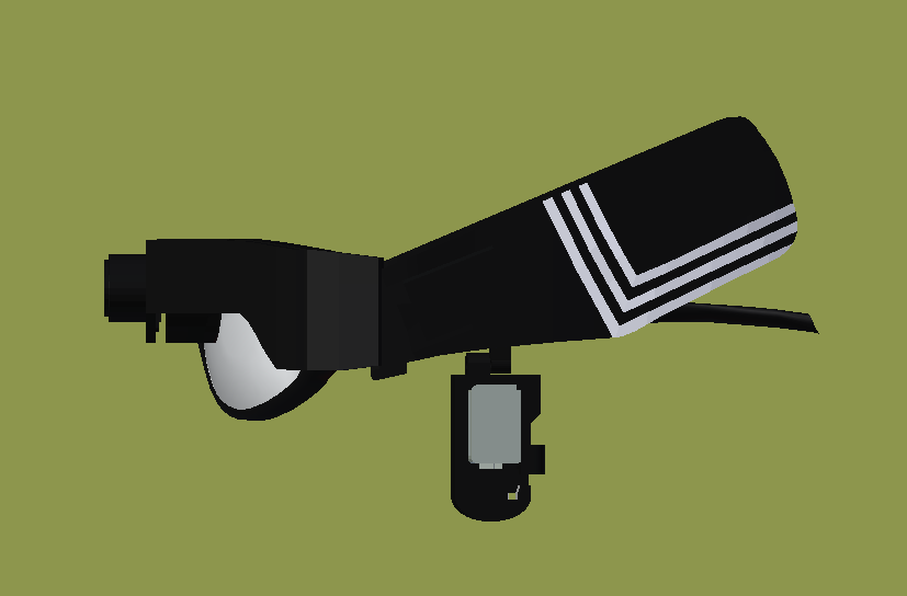
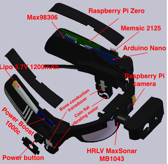
3D design of Visioneer V2.0
10/14/2017 at 06:44 • 0 commentsHere are 3D images of Visioneer V2.0 at different angles and an image showing labeled components in Visioneer's housings.
![]()
![]()
![]()
![]()
![]()
![]()
![]()
-
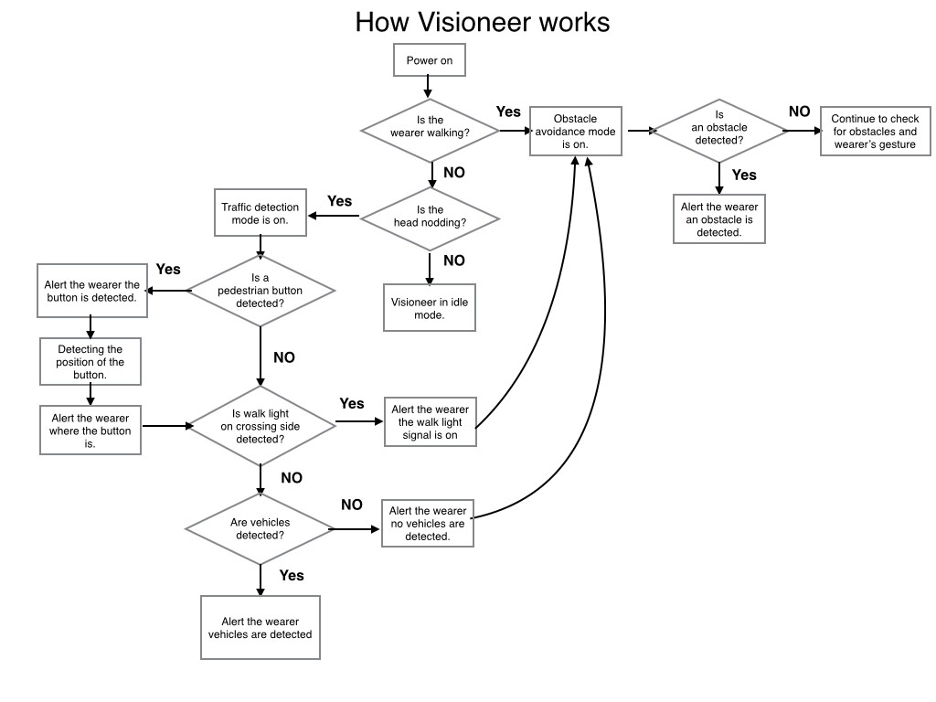
Updated functionality flowchart
10/12/2017 at 18:07 • 0 commentsIn this updated flowchart, Visioneer's functionality focuses on obstacle avoidance and traffic detection. We've added object recognition for pedestrian button and walk lights to improve traffic detection, helping the user determine when to cross the street.
![]()
-
Pedestrian hand button recognition
10/08/2017 at 01:14 • 0 commentsToday, Visioneer took its first baby steps toward classifying crosswalk objects! (pedestrian hand button)
As image gets closer (zoom to USB web cam), neural net eventually decides its not just random traffic and more likely to be a a pedestrian button. Zooming back out, you can see it decides picture is more like traffic overall. This represents how a user will need to be near enough to the button (be in crosswalk area) or else the neural net will only detect random traffic.
It is far from perfect (only 275 images of one button style and 275 of random traffic). I will try to get a total of 3000 images of the most common button styles in the U.S, along with 3000 of random traffic areas.
My next steps are:
1) Add real-time bounding box to "locate" where the button is in frame, for guidance.
2) Add walk signal (images of person walk symbol, not the word WALK) dataset, also with real-time box locator.
3) Deploy both Button and Walk detection to Pi Zero and test FPS in live scenario.4) Improve overall accuracy, while keep Pi Zero FPS high.
-
Gesture detection data
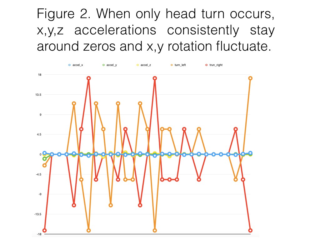
09/27/2017 at 04:26 • 0 commentsThe purpose of wearer's gesture detection by MPU6050 accelerometer/gyroscope on a testing prototype is used to activate obstacle avoidance mode or traffic detection mode. The test data below was collected as the wearer started stationary and then began to walk ( figure 1 ) and when the wearer turned their head ( figure 2). Notice there are zeros in the x, y, z accelerations in the pattern of walking. Values need to be averaged in the algorithm for next step.
![]()
![]()
-
Experiment on OpenCV, sensors, and bone conduction transducer
09/18/2017 at 13:09 • 0 commentsOpenCV experiment on color and circle detection with a traffic light picture. These techniques will be used to detect traffic lights for the traffic detection in Visioneer. Other OpenCV techniques will also be used for traffic detection.
The image of a traffic light arrow is detected with recognizing the shape of pentagon and rectangle using contour approximation from OpenCV.
Sensor experiment
Here are two videos of the experiment on LIDAR and MPU6050. The first video is testing two TOF LIDARs VL53L0. The conclusion is stable readings and narrow detection range. So we've decided to experiment with Maxbotix Sonar sensor for obstacle avoidance.
The second video is using MPU 6050 to detect movement of a user. Turning on red LED light means a user is stationary and turning on blue LED light means the user is walking or moving. It is a way to switch between two modes in Visioneer.
Testing audio output on bone conduction transducer
-
Deep Learning Experiment 1
09/16/2017 at 16:10 • 0 commentsThe first video shows my first experiment of live recognition using a Pi3, USB webcam, Movidius\Caffe and OpenCV on a pre-trained neural net called SqueezeNet.
The second video shows the same Pi3 setup classifying a single cat pic at 307ms. Hopefully you can see in the video the number 307523 which is = 307ms.Now that we have a successful benchmark for Movidius, we will turn our efforts to benchmarking without it, and using YOLO\Darknet instead of Caffe\Squeezenet.
After that, we will train\compile a custom neural net on traffic-related images which should achieve a faster recognition speed on either platforms. The goal is < 40 ms on a small custom set of objects.
-
Research: Accessible Pedestrian Signals
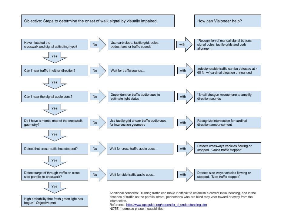
09/04/2017 at 04:53 • 0 commentsThe National Cooperative Highway Research Program Project 3-62, Guidelines for Accessible Pedestrian Signals highlights the procedure used by the visually impaired to cross an intersection.
http://www.apsguide.org/appendix_d_understanding.cfm
We've outlined the procedure and how Visioneer could help. Visioneer's phase two design will be implemented based on the outputs of the flowchart below.
![]()
Visioneer
AI glasses that provide traffic information and obstacle avoidance for the visually impaired.