 Joshua Elsdon
I enjoy making things that are a little silly sometimes. You will all be glad to know that this is one of those times! If you like small robots you should see the other project on which this work was most shamelessly ripped. Those robots are pretty small whilst maintaining almost all of what a roboticist would expect from a simple robot, odometry, line sensing, collision avoidance, uplink and downlink, robust and safe power electronics etc. The question arises: Could you make it smaller if removed most of the utility of the robot? The answer I believe is 'HELL YEAH', though time will tell.
Making a robot smaller than the existing design is a challange, as that robot was already designed with size in mind, and I can only find one or two robots that are in the same ballpark of size from other makers. The design presented here is roughly half the size of the smallest robot I can find.
First we must define what I mean by robot however. As some people would claim this is a robot, or this is robot. (for the record both of those things are beyond amazing). But for me I feel a robot must be controllable, have onboard sensors and processing and power. This is an arbitrary definition, though I think this would meet most peoples perception of 'robot'.
Below is my design so far:
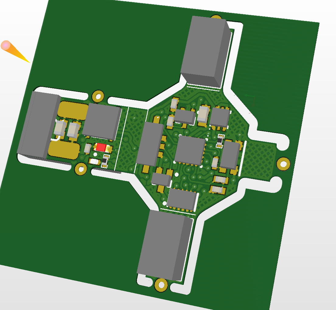
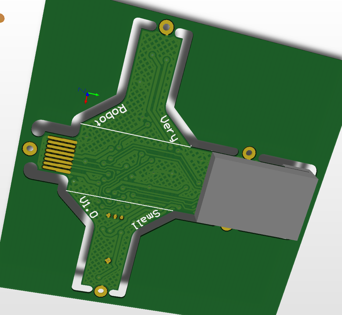
It is a little difficult to get a sense of scale, though the grey block in the second image is the battery which measures 8x12x2mm. You might say, 'hey, that isn't that small. that is nearly 30mm long'. But we have a trick up our sleeves. The robot will be manufactured on flex PCB, and fold up to radically reduce it's footprint. In the second image the battery will fold up and over by 180 degrees, such that it then lies between 'Very Small Robot V1.0", coming to an end just before the built in 8pin flat flex connector used for charging and programming.
This also means the electronics on the reverse side of the battery is now facing up. This is convenient as these are the IR reciever and transmitter and user LED. So we will be able to see and use those things, Hurrah!
Now the things that look like 'wings' are where the motors are mounted. In the first image the shafts of the motors would be facing into the middle of the PCB. We now can fold the 'wings' up to meet the battery, and the motors will now be at a 45 degree angle with the shafts pointing 'down' in the second image. The robot now has a footprint of just he centre hexagon shape, with the programming connector protruding. The robot will then use the motor shafts directly as wheels, perhaps with very thin silicone tubing slipped over them for grip. The total diameter of the robot will be 15mm (if you fold the programming header also) with a maximum height of about 10mm.
On the bottom is the M0 processor, a IR reflectance sensor, a 2.8v regulator and a dual motor driver. So we have not thrown away all the features. The robot can still be controlled over IR, and communicate back. It can still follow a line.
We no longer have any odometry, reverse polarity protection, battery charging, collision detection, multi-colour user LED and reliable programming connector. A small price to pay I am sure you all agree! Nothing like having the raw battery nodes exposed on a high density connector eh?
To charge the robot, you will have to use a special programming board that has the charging sub circuit. Luckily I designed one of them too :) (It also doubles as a pogo pin programmer for the Thermal Watch project.
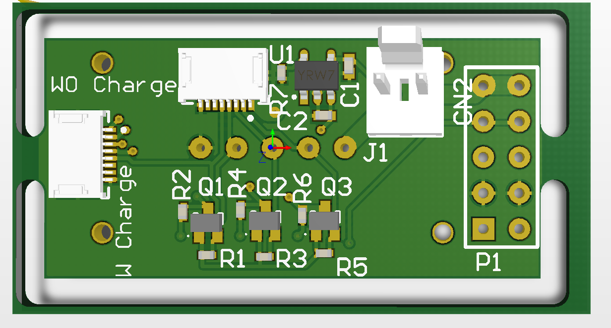
I will be prototyping this on rigid PCB first to save development costs. Wish me luck.
Discussions
Become a Hackaday.io Member
Create an account to leave a comment. Already have an account? Log In.