Close
0%
0%

longboardLight1

LED longboard light setup

Similar projects worth following
Lighting system for a longboard. Using sensors to control brake lights, indicator lights and ground tracking effects.
https://github.com/mattThurstan/longboardLight1

This project to light up my longboard with LEDs was mainly inspired by two things:

Firstly, i put one of my boards under a taxi (actually it was was friends board, which made it worse). Luckily it was only the board and not myself. On reflection of this incident, all i could say for certain was, if there had been lights on the board the driver of the car would have definitely seen me. ( On a side note, my Shark Wheels survived the encounter.. kudos. )


I really liked that board.

Secondly, I saw two projects whilst browsing the internet, both were attempts to track the wheel position on a skateboard and match it to the LEDs running down the board. That was such a cool visual trick, i really wanted to try it.

http://www.instructables.com/id/Ground-Tracking-LED-Longboard-Mod/

https://softsolder.com/2012/08/29/longboard-speed-sensing-ground-effect-lighting/

Both of these things happened in the same week and as i had some spare LED strip i though i would have a go.

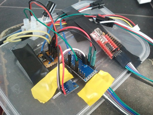
The rough concept which was then worked out involved battery power, a microcontroller, buttons, LED strips, sensors on wheels and a sensor to tell the orientation of the board. Based on this i then roughed out a set of modes which could be mixed and matched, mabye with animations as go-betweens.

  • Front/Rear lights. For safety so we can be seen when riding at night. Fade on when the board is placed horizontal.
  • Turning indicator lights. Utilising sensors we can detect when the board turns a corner and blink the direction. Avaliable when the board is horiontal.
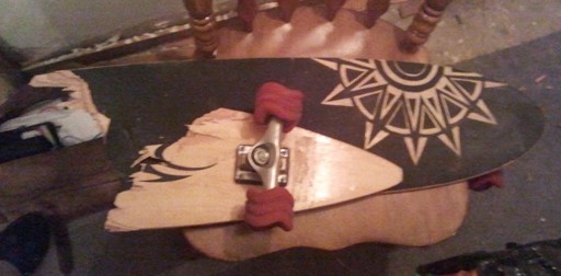
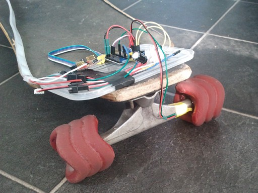
  • Stood vertical. Utilising sensors we can tell when the board is stood up. We then fade the LEDs to the bottom with an animation, then, if not turned off by the switch, the board will 'breathe'. (My main board has a unique feature, the rear of the board is in line with the wheels, meaning it can stand up by itself, very handy.)
  • Stood vertical (upside down). This will be dependent on whether the board in case has mirrored ends or a definite front and back. Most probably this will just be the inverse of 'stood vertical'. The only difference being the direction of the interceding animation.
  • Stood on it's side (either). This could be used for portable lighting, or as an emergency feature should you lose control of your board.
  • Breathing. The bottom few LEDs on the board will gently pulse a glow at 12 times a minute (average breathing time when sleeping?).
  • Horizontal underlights. Eventually many modes will be available when riding your board, from full colour flood, through blinks, to ground tracking patterns. For my purposes i only require a few, plus effects, as i will be just cruising around.
    • Full colour. Variable brightness and full RGB colour range.
    • Full colour with fade towards direction of inertia. eg. Skate forward and the light bunches up to the front and fades slight towards the rear. When you stop your board the light moves to the back of the board and the red tail lights get brighter. It will do this all at roughly the same speed as you do.
    • Ground tracking. Using our sensors we can tell exactly how the board is moving. this enables us to pull a visual trick.The simple version is to light up one LED on either side of the board, in the middle. Then, when the board moves, we move the light in the opposite direction at the same speed. This has the effect of making the light stay in the same position. This effect works better the more LEDs there are per meter. This one LED effect can then be expanded into patterns scrolling down the side of the board, except it looks like the patterns stay still, as the board moves. One mode could have repeating stripes the same length as the strips on the road. Another could track the road markings themselves if you skated down the middle of the road and turn the lights on to match.

  • 1 × Longboard Drop-down longboard
  • 4 × Shark Wheel Shark Wheels, based on a sine wave
  • 1 × Arduino Pro Mini ATmega328, 16MHz, 1K EEPROM, 5V
  • 1 × WS2812B addressable LED strip 30 LED/metre, pixel order = GRB
  • 1 × ADXL335 3-Axis Accelerometer Semiconductors and Integrated Circuits / Misc. Semiconductors and Integrated Circuits

View all 10 components

  • control

    matt thurstan08/07/2021 at 22:29 0 comments

    Hardware: 

    • Power switch (may convert to touch or waterproof button if charging system is implemented)
    • Reset button
    • WIFI button ??? - turn on/off

    Software:

    • WIFI access point (with menu for setting-up connection to home network)
    • Local hosted webpage for access to board lighting settings
    • Automatic switching from mobile device to home network when you get back to the house
    • Connection to the home network allows the lights on the board to be synced to lights in the room
    • When at home the board lights are added to the home automation menu (and the board is added as a device, with access to sensors and history data)

    Currently:

    1. If the WIFI is on the microcontroller runs a local Access Point. 
    2. A mobile device connects to the AP. 
    3. Using a browser to go to a webpage for controls and settings. 

    TODO:

    1. First startup (or full reset) - run WIFI AP with such options as save current device and connect to home network.
    2. Second startup - scan for saved devices/networks. 
      1. if home network found 
        1. then connect. 
      2. if mobile device found and no home network found 
        1. then run WIFI AP.
        2. [ user connects mobile device to AP. ]

  • first testing

    matt thurstan08/22/2017 at 13:01 0 comments

    ..

    ..


  • housing design

    matt thurstan08/22/2017 at 13:00 0 comments

    [ Spolier - It basically comes down to money (or lack of..) ]

    In order to do this justice it really requires a sleek waterproof housing moulded to the underside of the board, silicon lengths to put the LED strips inside and some pieces fitted to the trucks to hold the wheel sensor(s) and LEDs.

    One thing to note here is that the board i am fitting these lights to is a drop-down board (the middle of the board is lower than the ends). As there is a curve just where i would like to place the main housing, i can't just use an off-the-shelf box, it needs to be custom made. This also has ramifications for replication. Longboards come in many different shapes and sizes. I have 2 boards available which are of very different lengths. So when i come to putting lights on the second board, firstly it is a flat board and secondly i will nearly double the amount of LEDs used. This will then require a different shape housing and a re-calculation of the power requirements.


    As previously discussed, the main case is to be mounted under the board, just in front of the rear truck, the wheel sensors on the rear wheels, and power for the headlights is fed up through one of the side strips. The keeps the added weight central.

    So i opened up some 3D modelling software, made mock-ups of my board and the main components, and started to try out some sleek case designs i had in my head. The lowest profile possible, inset waterproof access ports, the works. Then i froze what i had and went for a quick look online to see what it would roughly cost to print one. ..well, that was a mistake, my bank balance laughed at me. [Edit: A friend of mine now has a CNC router which he has told me can mill a block of plastic the size i need, so i am going to attempt that sometime.]

    In order to waterproof the LED strips properly i would need to mold some silicon (or similar) low-profile pieces. This is starting to get quite expensive for a quick one-off idea. I like to skate in all weather so for me waterproofing is a must.

    For the time being then, i will be going with the electronics in a box, LED strips in the silicon casing it came with, and a hot glue gun. If i don't get proper waterproof housing by the time testing is completed i will most likely take it all off the board and shelve the project for a future time. Pity, but i would much rather use the board than have it sat on a shelf for fear the electronics would get ruined by rain or crushed on the edge of a pavement.

  • bonus feature

    matt thurstan08/22/2017 at 12:47 0 comments

    • The battery is bigger than needed.
    • The system is running at 5 volts.

    ..this means i can use the USB port i took off the power adapter, mount it on the side, and charge my phone while i am sat by the river!

    This could also be put to other uses, eg. when mounting a GoPro camera on the board it could be powered by USB, making sure it keeps on filming.

    Edit: Mounting GoPro's on a longboard doesn't work very well, far too much vibration.

  • put it all together

    matt thurstan08/22/2017 at 12:38 0 comments

    I taped the Arduino, accelerometer and wiring to the lid of a plastic box, then to the top of my board. Power is still coming via USB from my PC.
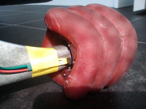
Close-up of magnets glued onto a crazy Shark Wheel.

  • wheel tracking

    matt thurstan08/22/2017 at 12:37 0 comments

    Software uses a custom library for ease of access.

    https://github.com/mattThurstan/MT_BoardWheels

    • BoardWheel - (single version) attempt to move all board wheel related items to a single library

  • orientation

    matt thurstan08/22/2017 at 12:37 0 comments

    Mounted next to the controller, in line with the centre of the board is an MPU6050 6-axis sensor on a GY-521 breakout board. It is connected to the microcontroller via I2C, powered with 5v and can data connect to board with either 3.3v or 5v

    Pro Mini:

    • A4 I2C - SDA
    • A5 I2C - SCL

    D1 Mini:

    • D2  4  I2C - SDA
    • D1   5  I2C - SCL

    Wemos D1 Mini (ESP-8266):

    • D1   5  GPIO5  IO  I2C - SCL
    • D2  4  GPIO4  IO  I2C - SDA
    • MPU6050:             X=Right/Left, Y=Forward/Backward, Z=Up/Down
    • orientation (byte):  0=flat, 1=upside-down, 2=up, 3=down, 4=left-side, 5=right-side
    • direction (byte):     -1=stationary, 0=forward, 1=back, 2=up, 3=down, 4=left, 5=right

    The software has several calibration routines to help work out where it is in space and time. 

    • A full calibration is run when the board can be placed on a level, solid surface for quite some time, preferably leaving the room please, haha funny, your jumping is not helping.
    • Short calibrations are run at startup when the board is placed on the ground. Current and saved data is compared to make slight adjustments to centre the orientation. 
    • Short calibrations can also be run by request, at intervals, or whenever needed by the program to self-correct.

    Orientation sensor data is used to switch light modes, change the speed of the animation, activate an emergency beacon, indicate when the board leans round a corner and mix with the wheel sensors to produce LED effects.

    TODO: Fix upside-down register. Seems to have a blind spot/gimbal lockout point?

    TODO: Proper calibration system with menu.

    Software uses a custom library for ease of access. 

    https://github.com/mattThurstan/MT_BoardOrientation

    • BoardOrientation - attempt to move all board mpu6050 sensor related items to a single library
      • 20 milliseconds read interval
      • 100 milliseconds main orientation read interval

  • lighting

    matt thurstan08/22/2017 at 12:36 0 comments

    ..

  • power

    matt thurstan08/22/2017 at 12:34 0 comments

    So far we have to accomodate the following components:

    • Arduino Pro Mini @ 5V
    • WS2812B LED strips. @ 5V
    • ADXL355 or MPU6050 @ 5V
    • Hall Effect sensor @ 5V

    The bulk of the power consumption will be taken up by the WS2812B addressable 5V LED strips. The power used by the Arduino and sensors is negligible in comparison.

    Here are my initial workings for the LEDs:

    • total LEDs = 40
    • power/mA per LED = 60
    • total power/mA = 2400 (full white) ( 75% duty cycle/mA = 1800 )
    • total power per colour/mA = 800  ( 75% duty cycle/mA = 600 )

    As well as the power of a battery we also need to consider the weight.

    I decided to go with a Lipo battery with a high discharge rate. These batteries can be small(ish), thin, and i don't need to worry about any heat build-up due to airflow under the board. You do have to be carefull with charging though. In looking for a battery the main issue i then had to consider was, what voltage? Within the voltage range i will be working it basically came down to a 3.6V or a 7.4V Lipo battery. As i really needed everything at 5V (so i didn't have to spend any money on more parts) i decided to go for 7.4V and convert it down to 5V. I also made the decision to totally over-power it. (It really *ing annoys me when batteries run out on devices. In this modern day and age of mobile devices it is amazing how many of them are not really, erm, portable.)

    With all that in mind i found on ebay a 7.4V Lipo battery for a quad-copter (2700mAh and a 10C discharge rate - that's high.. like take the power surge from a 100 LEDs suddenly turned on full high.. about 2.9A at max discharge).

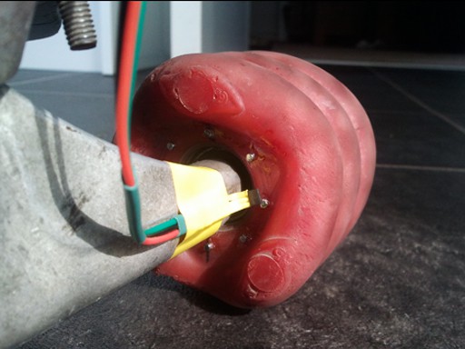
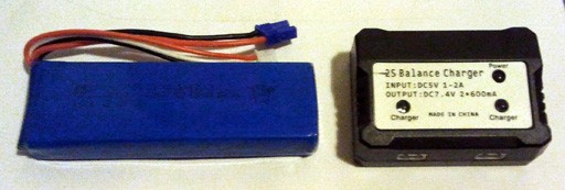
    With 40 LEDs this will give us about 2 hours use if all the LEDs are turned on at full-brightness. As the LEDs won't be on all the time, this lengthens the usage, add in some other tricks like duty-cycle reduction in the programming and we should end up with a 4-5 hours continuous maximum usage scenario. But, given the likelihood of NOT skating around with all lights constantly flashing at full brightness in convoluted patterns that give bystanders epilipsy, i am optimistic in hoping for at least 10 hours use between charges.

    Now we have to convert from 7.4V to 5V. I am going for a pre-built solution for this as my skills are not quite up to building a stable power convertor, small enough to fit under a longboard, and be of good enough quality that it won't do things like backfire and blow up the Lipo battery (oh, i've heard stories, but i'm no Tony Stark). So, on ebay (again) i found a small 'DC 6~35V to 5V 3A Double USB Converter Voltage Step Down Regulator Module'. I can feed the Lipo in one end and get regulated 5V power out the the other. I will probably removed the USB sockets from the board and attach the power lines directly.

  • initial design

    matt thurstan08/22/2017 at 12:33 0 comments

    Based upon the initial concept workings i know that we need to start with 4 strips of LEDs on the underside of the board, 2 long ones for left and right and 2 short ones for front and back, everything else gets designed around this.

    The initial offerings are going to be based around an Arduino Pro Mini (ATmega328, 16MHz, 1K EEPROM @ 5V) controlling strips of individually addressable WS2812B LEDs. This is simply because i have several Pro Minis and several meters of LED strip left over from making my desk and bookshelf lights. If things do not work out as planned then i will look into replacement components (eg. 3.3V based controllers), but, as always, these things require money.

    • The Pro Mini will be programmed using the Arduino IDE (not because i like it, just cos it's easier for the moment).
    • The WS2818B LED strips will be controlled using the FastLED software library.
    • For testing i will be using VVVV (on a PC) to receive and visualise any data produced (VVVV ..nodal-based live programming!!!). Eventually this will be superceded by a mobile app.

    The LED strips that i will be using have 30 LEDs per meter. On the drop-down board that i usually ride i can fit 18 LEDs for the long strips, and 2 (or 3) for the ends.

    After looking at some of the options for accurately tracking the rotation of an object, it became clear that ..i couldn't afford it. Custom made bearings with sensors inside, optical tracking printed onto the wheel, fast microcontrollers to keep up with the speed of rotation.., or i could just stick some magnets on the wheels and make do. So, 1 Hall Effect sensor, 8 magnets, and i get to keep the Pro Mini.

    For working out the orientation of the board it was clear that a motion sensor was required. I already had an ADXL355 chip but it might not do the trick, so i ordered an MPU6050 chip on a GY-521 breakout board (this is of the type used in the average mobile device).

    In the future i would like to add wireles communication and a mobile app to control the board. I will most likely add a seperate ESP8266 board, or upgrade (if i can find one) to a 5V microcontroller with embedded WIFI/Bluetooth.

    For mounting the parts on the board they need to be cased, underneath the board, attached firmly, waterproof and be mounted centrally.

    That's quite a tall order.

    For firm attachment to the board the best option seems to be via the screws that hold the trucks. Board setups already use rubber spacers to affect the ride, so it seems reasonably to sandwhich the housing attach points between 2 half-size spacers. This would then mean either a long case reaching from end to end, or a small case, but shifted towards the back of the board.

View all 12 project logs

Enjoy this project?

Share

Discussions

Similar Projects

Does this project spark your interest?

Become a member to follow this project and never miss any updates