 Daren Schwenke
Did a couple virtual experiments with how I could hinge the corners to enable 'spin folding'. Rotate the top 60 degrees and it lowers to sit on the matching bottom.
Right now, you have to actually remove the 6 vertical members to fold it down. This would allow you to just unhook and fold up 3 of the arms, and then turn/lower the top to meet the bottom with the remaining 3 arms still attached at both ends.
Using ball joints this would be super easy, but that would also sacrifice a ton of rigidity. Making the joints as pivots will work much better, but then the pivot axis vector and arm length/position has to be carefully planned.
Here is the best I got so far.
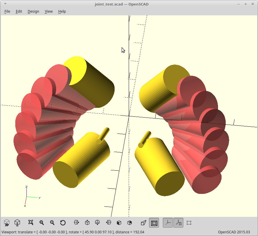
The large yellow cylinders are the current angles needed by the joints, and the pink ones are what you get when you rotate them about the axis represented by the smaller yellow cylinders. The rotational axis vector was determined first and properly (as best as I can tell with just the math) represents the swing required of the arms during the 'spin fold'.
Then I just iterated on offsets of the rotational axis until I got a path where the arm length matches reality.
I believe if I put a hard stop in the rotation in the extended position which is attached to the part of the triangle that stays static, I won't be giving up as much rigidity to do this either.
The current iteration is still not good enough though, as that folded arm position intersects with where I currently have stepper mounts.
It's a side goal, and the rest of the project can move on without it, but this would definitely be cooler.
EDIT: If anyone is ambitious enough to check my math, here is the 'so far' joint model in OpenSCAD.
Only works for one of the two joints though, as the second joint (from the opposing arm) would actually occupy the same space as the first when folded... but that's just details. :) I could use a different set of offsets for that joint, and the ends don't acutally have to line up as they will be disconnected for that one.
module joint_test() {
    wall_thickness=2;
    support_rod_dia=8.25; // Driveway marker diameter.
    support_rod_depth=20; // Depth of the pockets for support rods.
    roswell_constant=19.47;
    q=32;
    x=q/2;
    y=q/4;
    z=q/8;
    translate([x,y,z]) rotate([0,45+roswell_constant/2,0]) {
        cylinder(r=1,h=30,center=true);
        for (i=[15,30,45,60,75,90]) rotate([0,-45-roswell_constant/2,-i]) translate([-x,-y,-z]) rotate([-30,roswell_constant,0]) translate([0,0,support_rod_depth*1.5]) #cylinder(r=support_rod_dia/2+wall_thickness,h=support_rod_depth,center=true);
    }
    translate([x,-y,z]) rotate([0,45+roswell_constant/2,0]) {
        cylinder(r=1,h=30,center=true);
        for (i=[15,30,45,60,75,90]) rotate([0,-45-roswell_constant/2,i]) translate([-x,y,-z]) rotate([30,roswell_constant,0]) translate([0,0,support_rod_depth*1.5]) #cylinder(r=support_rod_dia/2+wall_thickness,h=support_rod_depth,center=true);
    }
    rotate([-30,roswell_constant,0]) translate([0,0,support_rod_depth*1.5]) cylinder(r=support_rod_dia/2+wall_thickness,h=support_rod_depth,center=true);
    rotate([-30,90,0]) translate([0,0,support_rod_depth*1.5]) cylinder(r=support_rod_dia/2+wall_thickness,h=support_rod_depth,center=true);
    rotate([30,roswell_constant,0]) translate([0,0,support_rod_depth*1.5]) cylinder(r=support_rod_dia/2+wall_thickness,h=support_rod_depth,center=true);
    rotate([30,90,0]) translate([0,0,support_rod_depth*1.5]) cylinder(r=support_rod_dia/2+wall_thickness,h=support_rod_depth,center=true);
}
joint_test();
Discussions
Become a Hackaday.io Member
Create an account to leave a comment. Already have an account? Log In.
Well, I am not talking about the mechanics at the hinge itself. That looks OK. The issue is whether the hinge points to the corner at the top. Moving the axis of rotation elsewhere does not change anything about my argument above.
I extended the rods and added the cylinder the top corner need to move on. This shows very clearly why this won't work:
module joint_test() {
wall_thickness=2;
support_rod_dia=8.25; // Driveway marker diameter.
support_rod_depth=600; // Depth of the pockets for support rods.
roswell_constant=19.47;
q=32;
x=q/2;
y=q/4;
z=q/8;
translate([x,y,z]) rotate([0,45+roswell_constant/2,0]) {
cylinder(r=1,h=30,center=true);
for (i=[15,30,45,60,75,90]) rotate([0,-45-roswell_constant/2,-i]) translate([-x,-y,-z]) rotate([-30,roswell_constant,0]) translate([0,0,support_rod_depth*.5]) #cylinder(r=support_rod_dia/2+wall_thickness,h=support_rod_depth,center=true);
}
translate([x,-y,z]) rotate([0,45+roswell_constant/2,0]) {
cylinder(r=1,h=30,center=true);
for (i=[15,30,45,60,75,90]) rotate([0,-45-roswell_constant/2,i]) translate([-x,y,-z]) rotate([30,roswell_constant,0]) translate([0,0,support_rod_depth*.5]) #cylinder(r=support_rod_dia/2+wall_thickness,h=support_rod_depth,center=true);
}
rotate([-30,roswell_constant,0]) translate([0,0,support_rod_depth*.5]) cylinder(r=support_rod_dia/2+wall_thickness,h=support_rod_depth,center=true);
rotate([-30,90,0]) translate([0,0,support_rod_depth*.5]) cylinder(r=support_rod_dia/2+wall_thickness,h=support_rod_depth,center=true);
rotate([30,roswell_constant,0]) translate([0,0,support_rod_depth*.5]) cylinder(r=support_rod_dia/2+wall_thickness,h=support_rod_depth,center=true);
rotate([30,90,0]) translate([0,0,support_rod_depth*.5]) cylinder(r=support_rod_dia/2+wall_thickness,h=support_rod_depth,center=true);
cr = sqrt(3)/3 * support_rod_depth;
translate([cr, 0, 0]) cylinder(r=cr, h=600);
}
joint_test();
Are you sure? yes | no
Thinking a bit more about it: Things can probably improved by tilting the axis of rotation towards the corner of the triangle created by the old and new position of the moving rod. There should be still a degree of freedom left to adjust the angle of the axis while keeping the both positions constant. But as the program is setup right now I can't fix that that easily. May be you can revisit your formulas and place the axis better.
If you want another mathematical constraint just make the end of the rod touch the cylinder half way down.
Are you sure? yes | no
I'll try that. Now that I got another visual tool, some iteration may yet yield an answer.
Are you sure? yes | no
Looks like you are right. Thanks for taking the time to show me. Perhaps I could still build the required motion into the surface of my hinge, or just have the hinge be looser in the middle of the travel. Like two sine wave washers meshing with the peaks meeting in the extended position. 3D printing means it doesn't have to be a pin after all.
Are you sure? yes | no
Well, at least mathematically it won't fold with simple hinges. The movement may be hinge like enough to still work if something gives a little.
I am assuming you are doing a symmetrical movement which keeps the top triangle parallel to the bottom one. So all three top hinges move on a cylinder created by the circumference of these two triangles. They also have to stay on the sphere around the bottom joint - assuming they stay connected with a rod.
So the path of the top hinges are on the intersection of a upright cylinder with a sphere that has it center on the cylinder wall and has a diameter between die radius and the diameter of the cylinder. This looks a bit like the edge of a potato chip and does not fit into a plane. As a result folding cannot be done with hinges.
I still think the rigidity of the construction is mainly achieved with the triangles between the corners and does not need to rely on the stiffness of the corners. So using ball joints should not weaken it too much.
Are you sure? yes | no
Yes it looks like it did work with simple hinges, if the pivoting axis of the hinge was pointed basically at the center of the build area. Ended up being a 45+19.47/2 degree down angle off of horizontal and otherwise pointed at the center when I modeled it. With the hinges like that, the arms trace the arc of a sphere. OpenSCAD isn't constraint based per say so I could be wrong, but it looks right so far. I'll print a mini version and just try it, but it will be a day or two.
I threw my code for the test in the post up above if you wanted to play around with it. Extend the cylinder length and you'll see it trace the sphere shape. I think the trick was not pivoting at the actual octahedral joints, but a little off center and then undoing the translation again after the rotation. Figuring out the arm length staying the same was just iteration and it's pretty close, but not perfect. Nice round divisors for my offsets though...
The end points of the triangles will be rock solid. It's the points slightly off axis (the pulleys) where differences in tension introduce twisting moments into the rods which I need to stabilize.
Are you sure? yes | no