 MrWunderbar
Mailbag
I ordered all the parts and after a few days full of anticipation, they finally arrived in my mailbox:
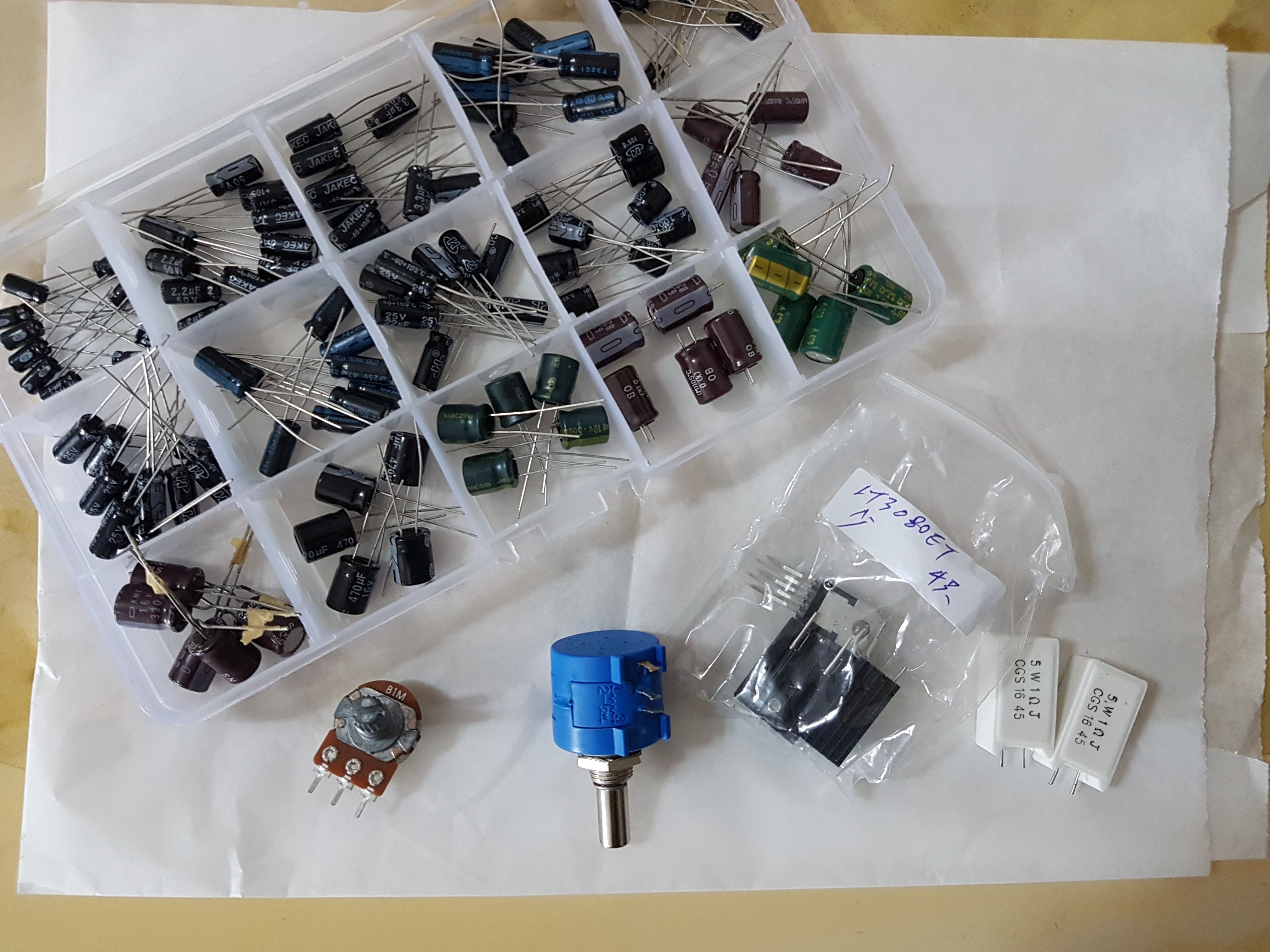
Actually not so many components, just a few resistors are not shown here. And also the terminals and plugs are not in this picture.
Prototyping
First, I tested the LT3080s one by one as a pure voltage regulator and the results were very promising. I could easily step down the voltage in millivolt increments by using a multi turn potentiometer. It just wouldn't go down to 0.00 V without any load attached, which is a standard characteristic of the LT3080. The lowest I could get was at around 890 mV, and when I attached a dummy load of less than 50 Ohms, it went down to the desired 0 V.
Then I went on and built the prototype on breadboard according to the schematics. The current limit control worked as expected and heat dissipation wasn't such a big issue. The small heatsinks did quite a good job at protecting the LT3080s from overheating. But I haven't tested a full scale 1 A load at 10 V yet.
Pitfalls
LM334 Current Source
The weirdest and most unexpected behaviour came from the LM334 supposedly provides current source to the LT3080 in order to keep the voltage regulation stable.
(Also see the Datasheet of the LT3080, page 4, Note 3 and Note 9).
In general, the minimum load current requirements are met with the LM334 and a simple 100 Ohm resistor, but:
BUT: the resistor took a significant amount of current with increasing set voltage. When the Voltage was set to below 5 V, it worked just fine, but I ramped it up to 10 V and the 100 ohm resistor started heating up and it produced a very unpleasant smell. Bye, bye, resistor... first victim of the prototyping.
I had 5 different LM334s and tried several and always the same result. So either the circuit design with an LM334 isn't great, or I just got the wrong part sent...
So I studied different schematics again, and tried the original schematic from microcontroller.it where he just added a simple 1k resistor to the output. And the whole circuit worked again without overheating the minimum load current resistor. So no LM334 needed after all.
Voltmeter & Instrumentation
I also ordered a cheap digital volt and ammeter:
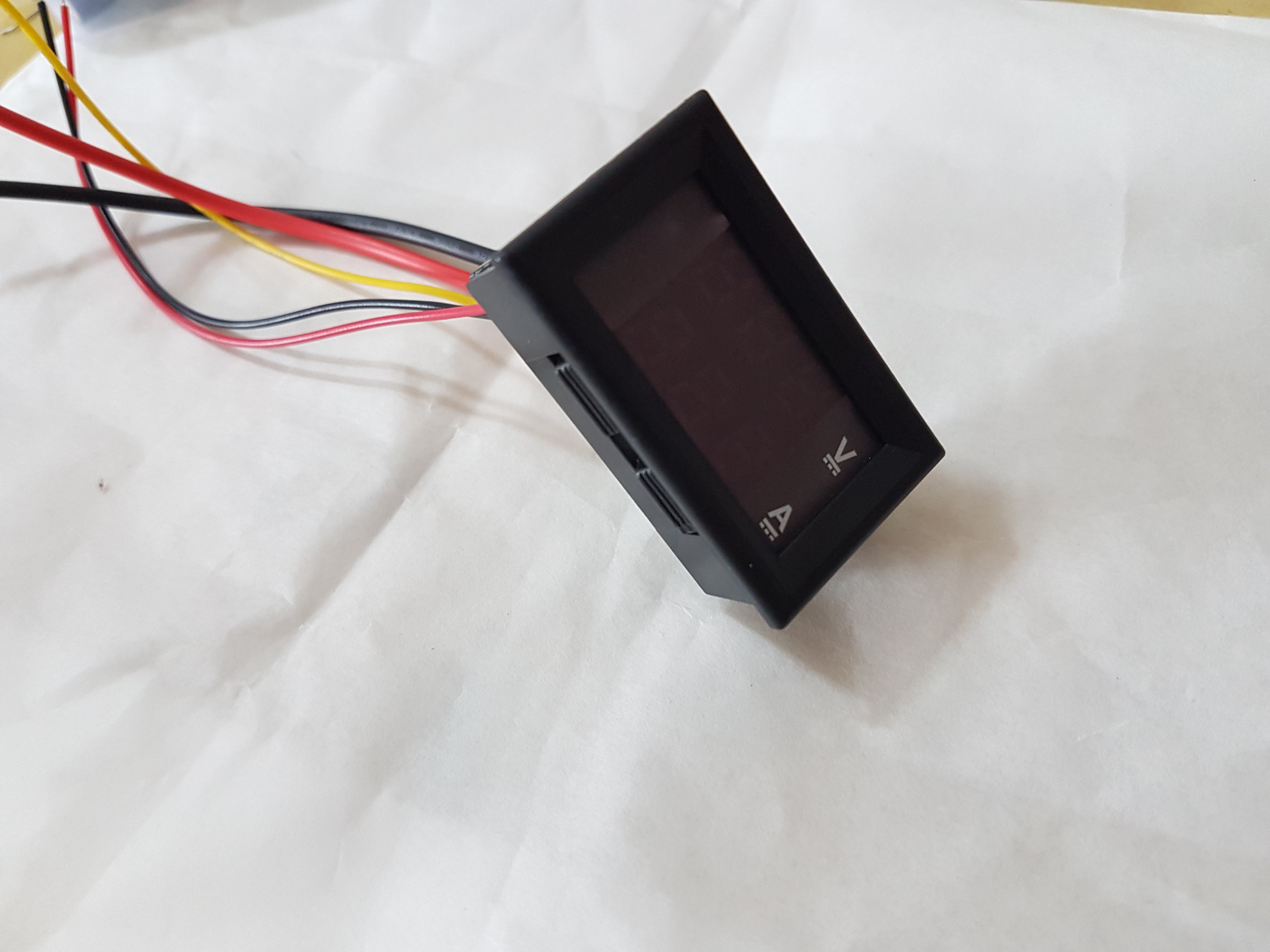
This thing didn't only cause trouble, it is also horribly imprecise.
Firstly, the ammeter suddenly drew a lot of current from the LT3080. The regulator failed and now it has a permanent damage (offset voltage of 2 V). Second victim of my prototyping...
(maybe, I just connected it improperly the first time...)
Secondly, the voltage reading is very unprecise. It has only 100 mV steps and those are off by 200 - 500 mV. This voltmeter is a toy, not a precision instrument. I guess you get what you pay for.
So I checked online for alternative parts, but precision panel voltmeters easily cost more than 20 USD, and that doesn't include current readings.
This also caused the first spark in my head to switch to a digital design. Because: "hmm... with a simple 16bit ADC and an ATMEGA I can easily create a voltmeter that is more precise than this thing..."
Or I would just leave the panel meters out completely and use my multimeter to set the voltage. But then again the trade off to not knowing the current limit precisely. It is a trade-off between cost and functionality.
Going down to 0 Volts
In order to get the LT3080 to go down to true 0 V, it needs to have its minimum load current (1mA) fed back to a negative voltage (see page 10 of the datasheet). So I was checking different ways of achieving it and looked at different charge pumps. But a charge pump would add another component and extra cost. And I wasn't sure if it would actually work so well.
But I found a simple circuit that can generate a negative voltage by using a oscillating input voltage, two diodes and two capacitors: https://en.wikipedia.org/wiki/Charge_pump
How to get an oscillating voltage... getting an oscillator. So another part... therefore, I could use a proper premade charge pump anyways. But then it sparked that I can use my Arduino to generate a PWM that oscillates the charge pump circuit.
And bam! It worked! I hooked up the self made Arduino charge pump to the minimum load current resistor and the LT3080 went down to 0 V.
This also made the decision final to change to a digital design.
Using a DAC to set the Voltage
Almost final part of this entry: my attempt to use my beloved MCP4922 to set the voltage of the LT3080. The first try with a pure 5 V input rail (5 V for Arduino, LT3080, DAC) worked quite well and I could set the voltage digitally.
Then I thought: hey, let's try with 12 V on the LT8030... and the next component fell victim to my stupidity.
The LT3080's set pin wasn't grounded properly, so 10 V went into the DAC output pin and fried it.
Next time: check the wiring carefully!
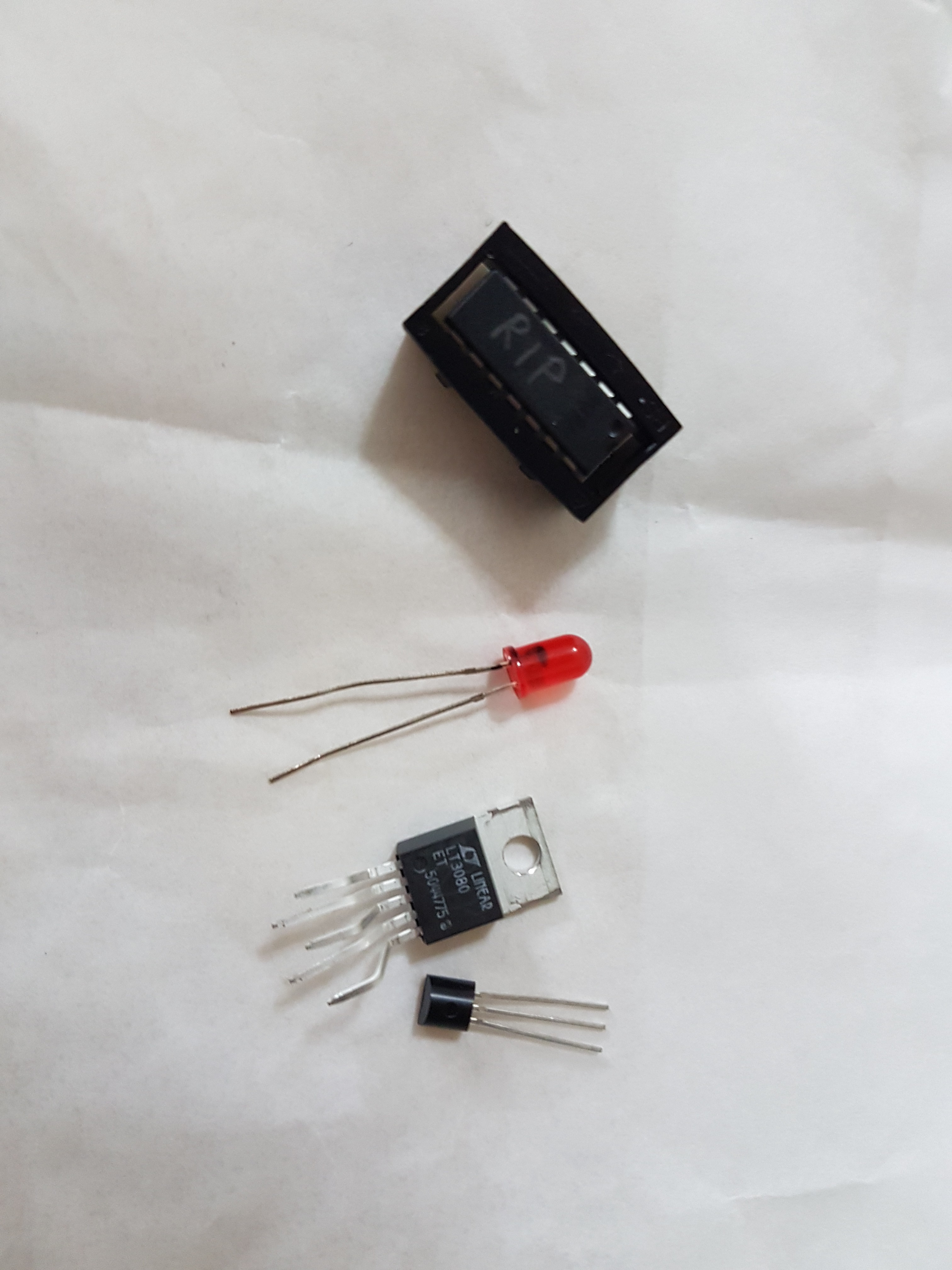
Victims of my prototyping, may they rest in peace:
Moving on
So the decision is final for me to change to a digitally controlled design. It increases precision drastically and makes lot of things easier. But I have bigger plans ahead with this Lab Power Supply. Waiting for more parts to arrive...
TBC
Discussions
Become a Hackaday.io Member
Create an account to leave a comment. Already have an account? Log In.
>16bit ADC and an ATMEGA I can easily create a voltmeter that is more precise
With the built-in ADC in your AVR, you already have 10mV resolution for 0-10V. That's 0.00V to 10.00V - that's the reason why I picked that range. I have voltage and current sensing circuits in my project that may be of interest: I am using 3.3V, so you might need to adjust resistor ratios.
https://hackaday.io/project/19078-adjustable-linear-bench-supply-in-1k
FYI: It is a lot easier to sense current on the input side than output. Just need to subtract it off.
I don't recommend the LM317 circuit as the configuration with integrator has power on glitch. It would work better on a different type of regulator with negative feedback instead. Also working on the much bigger brother which is lot more complicated.
Are you sure? yes | no
Nice write-up! That component-label on the ziploc bag looks quite Chinese... Did you order parts from china? Those low-end semis like your LM334 get copied like crazy. Had trouble with similar parts, for prototyping I order from reputable sellers only... Sometimes you want to throw away your whole project just because some of the components behave strangely and you don't know why...
Are you sure? yes | no