Close
0%
0%

DINuino anyone? Industrial packaging!

The Arduino world offers a ton of H/W options and excellent S/W.
Making a real industrial project out of it... not so easy.

Similar projects worth following
I design & build custom industrial-control products, including equipment test-fixtures. Some of these projects would have likely been quicker/better/cheaper overall if I could have leveraged Arduino-compatible products & S/W, but packaging them into something neat, clean, stable and reproducible (and 24VDC-power compatible!!) has always been a hurdle.

That's where DINUino comes in. I have a particular "DIN mounted" form-factor that I've used for 25yrs+, and many of those devices are still operating today (any 87C196KD20 fans out there?)! Clients continue to ask for enhancement and upgrades - all of which of course have to fit into existing spaces and wiring plans.

Can DIN-mounting of Arduino-compatible products be implemented other ways? Definitely YES! There are several existing solutions, However, they didn't offer the flexibility I wanted, nor the form-factor I needed.

On Tindie, eventually.

System overview:

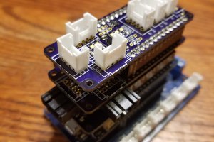
As you can see in the gallery, here's a set of metal parts with a smattering of mounting holes. All of which enable convenient mounting of Arduino-format boards, plus my own DINuino-format prototyping boards and related custom designs. 

They can be packaged "open-frame" by utilizing just the L-shaped DIN mounting plate.

You can also attach the 3 cover pieces to create a fully enclosed device.

My first DINuino prototyping board (shown) offers a place to plug in an Arduino (UNO to MEGA sized) CPU module. A standard 0.1" grid of holes can be utilized for your custom circuitry. You can find more on this prototyping board in its own project area.

DIN-Uino Mounting Plate:

* Base-plate can be used for open-frame project, but it is designed to accept a cover so you can create a fully-enclosed project.

* Intended primarily for projects that use the DIN-Uino carrier board.

* Can also be used with Arduino-compatible hardware alone. In this case, the Arduino "CPU" module would mount directly to the base-plate. There are numerous holes that allow you to mount the "CPU" either face-up or face-down. Use standard M3 (or #4-40) hardware/spacers/etc.

* 1/16" thick aluminum (all metal parts are the same thickness).

* Features a mounting-foot: After clipping your module to a DIN-rail, this foot allows you to firmly affix (and ground!) your module to the mounting plate.

* DIN-rail clip: Metal, spring-loaded. Standard catalog item from Hammond Mfg. This clip does NOT need a tool, just push down swing away from the DIN-rail. Remove the mounting-foot screw first of course - if you're using that feature.

Cover:

The cover plate normally would come blank (for your own custom application). As shown, it is configured to fit with the DINuino-MEGA-B prototyping board, thus allowing access to the power-input, LEDs, and Phoenix connectors.

Side-plates:

These plate are designed to be symmetrical - they can be used on the left or right side. However, the configuration shown in the gallery - has the left side plate with a couple of connector holes - which line up with the power and USB connector on a typical Arduino-Mega-2560 board. Of course, for your custom applications - cut your own holes into blank plates!

DIN enclosure size:

The current set of cover+sideplates are designed to implement a 42mm wide DIN module. However, a taller cover (and taller sideplates) can easily be designed to make larger enclosures. The base-plate always remains the same.

  • DIN-Uino Progress...

    Ed Caceres08/24/2017 at 17:29 0 comments

    Some of you may recall a similar project from back in late 2017. I've been pretty busy and just recently had time to re-visit this project - and I'm actually getting parts on order!

    17-Jul-2020:

    Boards have arrived: The DINuino-MEGA-B prototyping board. FYI, this name means that it's meant for an Arduino "Mega" sized CPU boards (also smaller ones, like UNO's), and the CPU board mounts to the bottom of the PCB. This allows you the flexibility to stack on some standard Arduino-compatible shields too, to round out your intended "system".

    Actually I forgot to order parts - so I have to do that now... I've been ordering a lot of parts lately and projects sometimes slip through the cracks.

    Prototyping board notes, POWER distribution:

    Externally, this prototyping board expects 24VDC (nominally a 12-25VDC range).

    Internally, there are two SMPS regulators: 9VDC which feeds directly into the Arduino board's "VIN" pin, and also 3.3V/5V (selectable) rail which is intended to power your custom circuitry which you're adding onto the Arduino.

    If you look closely at the pics of this prototyping board - you'll see two sets of pads/holes. 

    The larger pads are meant for your through-hole parts & IC sockets, or whatever you want to mount to them. These pads are not connected to anything on/in the board. Use them freely.

    The smaller pads are a secret convenience - for wiring up power & ground!

    These little pads are connected to the internal POWER and GROUND plane on the board. To use them - simply solder a bit of 28AWG wire from your IC/device, over to the nearest pwr/gnd pad. The POWER plane pads have a circle around them. The GND plane pads do not.

    Over in the power supply section, you can then select (via a jumper) whether the 2nd SMPS regular will provide 5V or 3.3V. You can then also choose to drive the internal POWER plane with this voltage (or not). It flexible and lets you define what your main PCB power rail needs to be. You could even change the 3.3/5V rail to something else - if you want to change a voltage-divider resistor.

    10-Jul-2020:

    All metal enclosure parts are on order!

    "DINuino-Mega-B" prototyping boards are also on order!

    I think the boards will arrive in a week or two.

    The metal will likely take a week longer.

    Some details:

    Baseplate:

    As shown, it has several hole patterns to accommodate a range of configurations:

    * Arduino UNO or MEGA sized board: Mounted all by itself (and with its shields). Can be mounted face-up or face-down.

    * DINuino prototyping board: With room underneath for an Arduino UNO or MEGA sized board.

    Cover:

    Generally comes "blank", so you could cut your own holes. The initial batch of covers will be pre-cut to fit nicely with the DINuino-Mega-B prototyping board.

    Side-plates:

    Generally come "blank", and they're symmetrical. However, the initial batch of left-plates will have appropriate connector holes for a standard Arduino Mega 2560 board (power & USB).

View project log

Enjoy this project?

Share

Discussions

Similar Projects

Does this project spark your interest?

Become a member to follow this project and never miss any updates