 Adam Sifounakis
Overview:
How did I go from simply wanting to assemble a wooden model of a TARDIS to buying about $100 worth of stuff to paint it, make it light up, play audio, and pulse its lights to the sound?
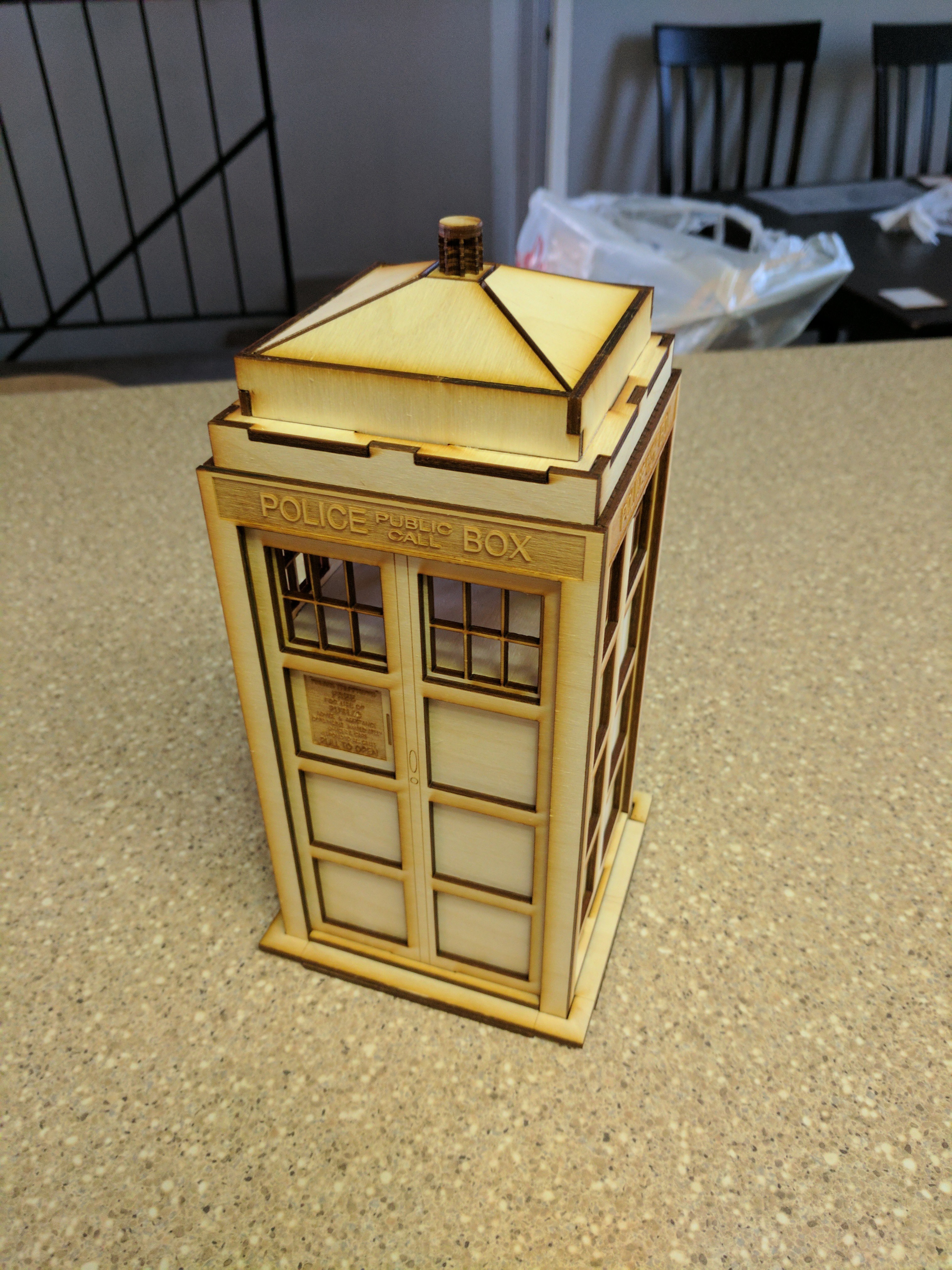
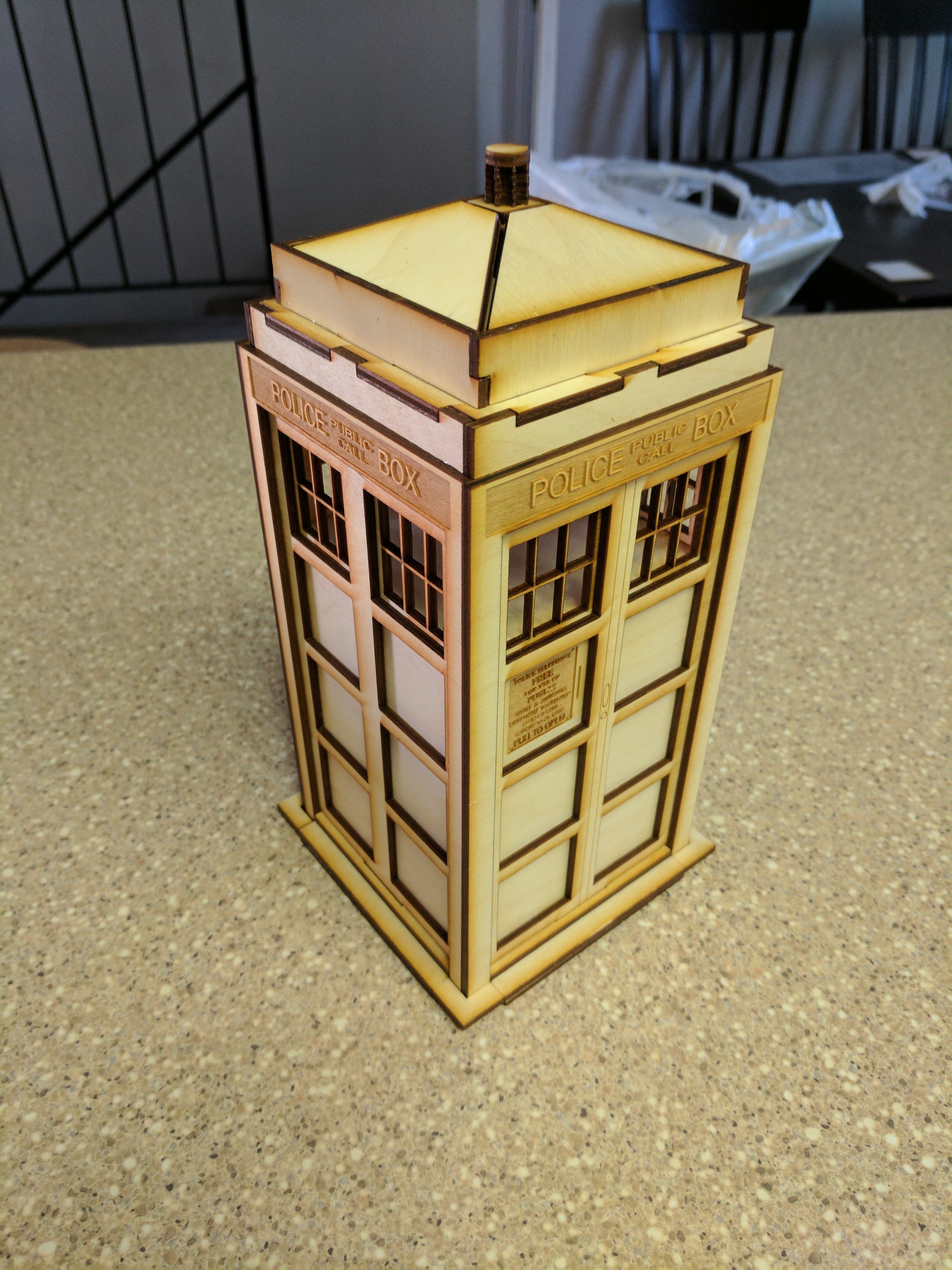
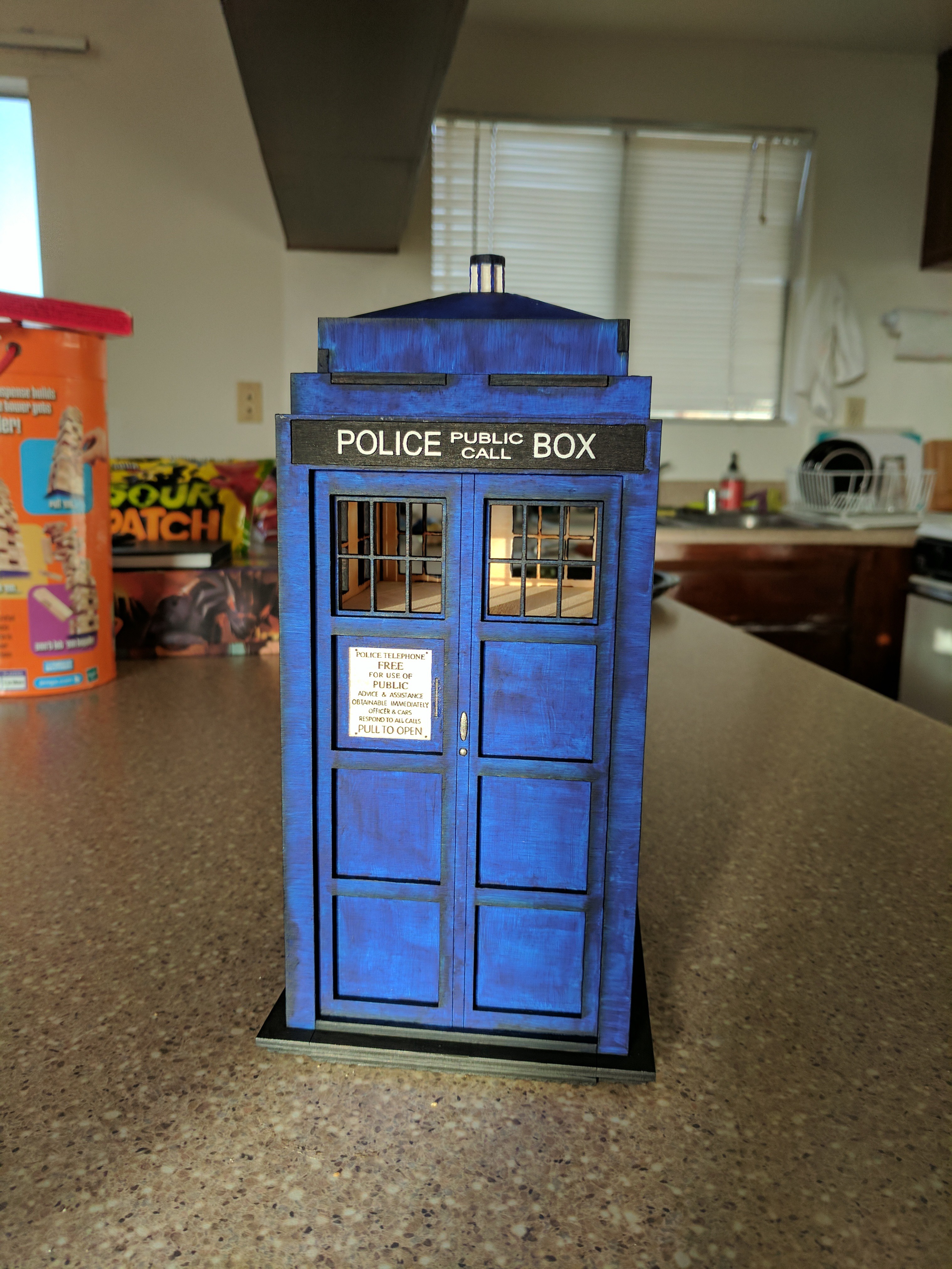
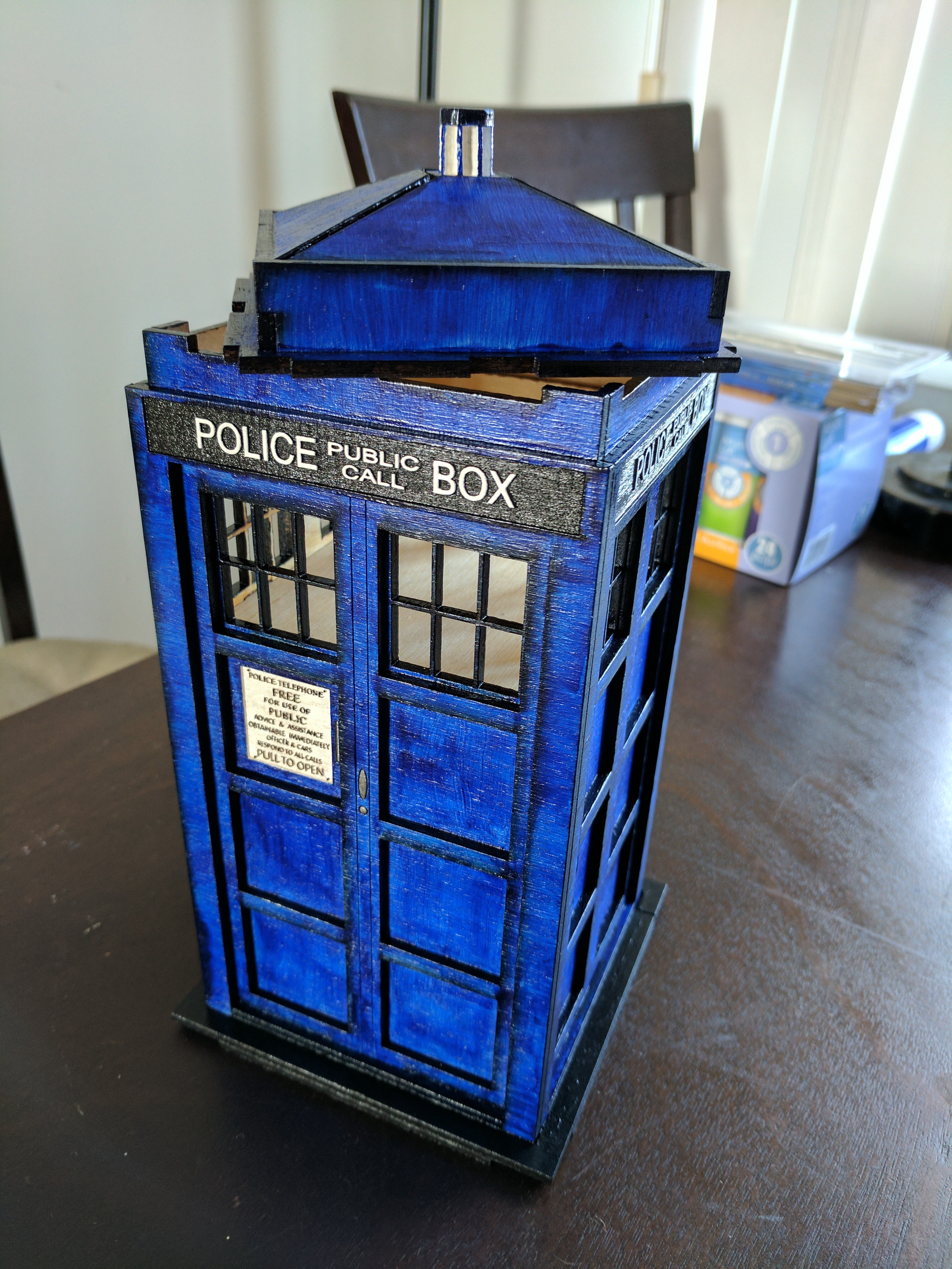
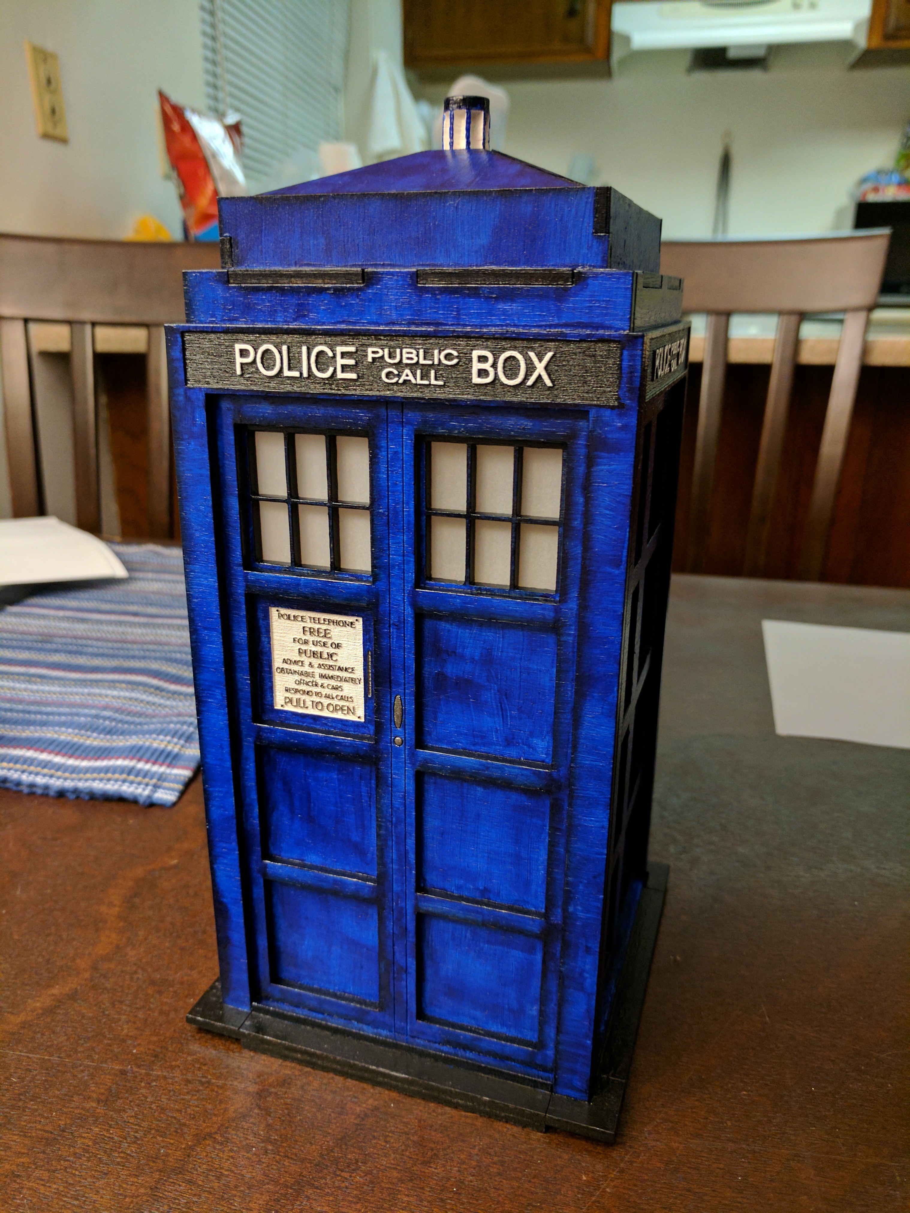
But before we answer that, let's start off with the final result to whet your appetite!
It was not incredibly difficult to make, but it was the result of a few weeks of effort and quite a lot of (im)patience.
This whole write-up is more of a story than it is a how-to for this project, but it'll still cover:
- materials needed (parts, schematics, code, etc.)
- necessary steps to build the TARDIS
- steps I actually took to build the TARDIS
- Ideally, this should be the same as the "necessary steps" list, but it pretty much never is...
- lessons learned
Enjoy the ride!
So how did this start?
I was walking around Fiesta Hermosa during Memorial Day weekend in 2017 when I ran into the LAZERMODELS stand. They had a lot of really cool models, but the one that caught my eye was a beautifully painted TARDIS.
I only started watching Doctor Who (2005+) about 2 years ago (2015), but I fell in love with it something awful. Now I'm not typically someone that buys trinkets for things I like, but I was looking for a fun little side project to work on and this seemed like something I would enjoy looking at every so often.
And, as all projects go, it kind of spiraled out of control:
I'll just assemble it and it'll be fun!
Hm... I really liked how it looked painted. Maybe I'll paint it...
The guy at the stand had mentioned that someone put a light in the top part. That could be neat!
Well, I really don't want to put a hole in any of the walls, so I guess I'll have to make it battery powered.
I wonder if I can have it make the TARDIS sound and pulse the light in time with the sound.
I really don't want to have the sound playing all the time, so I'll need to be able to trigger it (again, without putting holes in the thing). Oh! I could have it be snap-activated, just like the TARDIS was in the episode where the Doctor first meets River Song! (Forest of the Dead - S04E09)
Note: Here are the finger snapping references in Doctor Who:
Materials Needed
- Blue Box (Tardis) Wood Model Kit
- Wood glue
- Paint brushes
- Paint
- Aquamarine Blue
- Obsidian Black
- Titanium White
- Clear coat
- White Vellum
- Adafruit Pro Trinket 5V
- Adafruit Pro Trinket LiPoly Battery Backpack Add-On
- LiPoly Battery 3.7V 2500 mAh
- Electret Microphone w/ Tunable Gain
- Icstation programmable audio board + speaker
- Six Warm-white LEDs
- Six 130Ω resistors
- Six 47μF capacitor
- Protoboards
- Slide switch
- Wires
- Solder
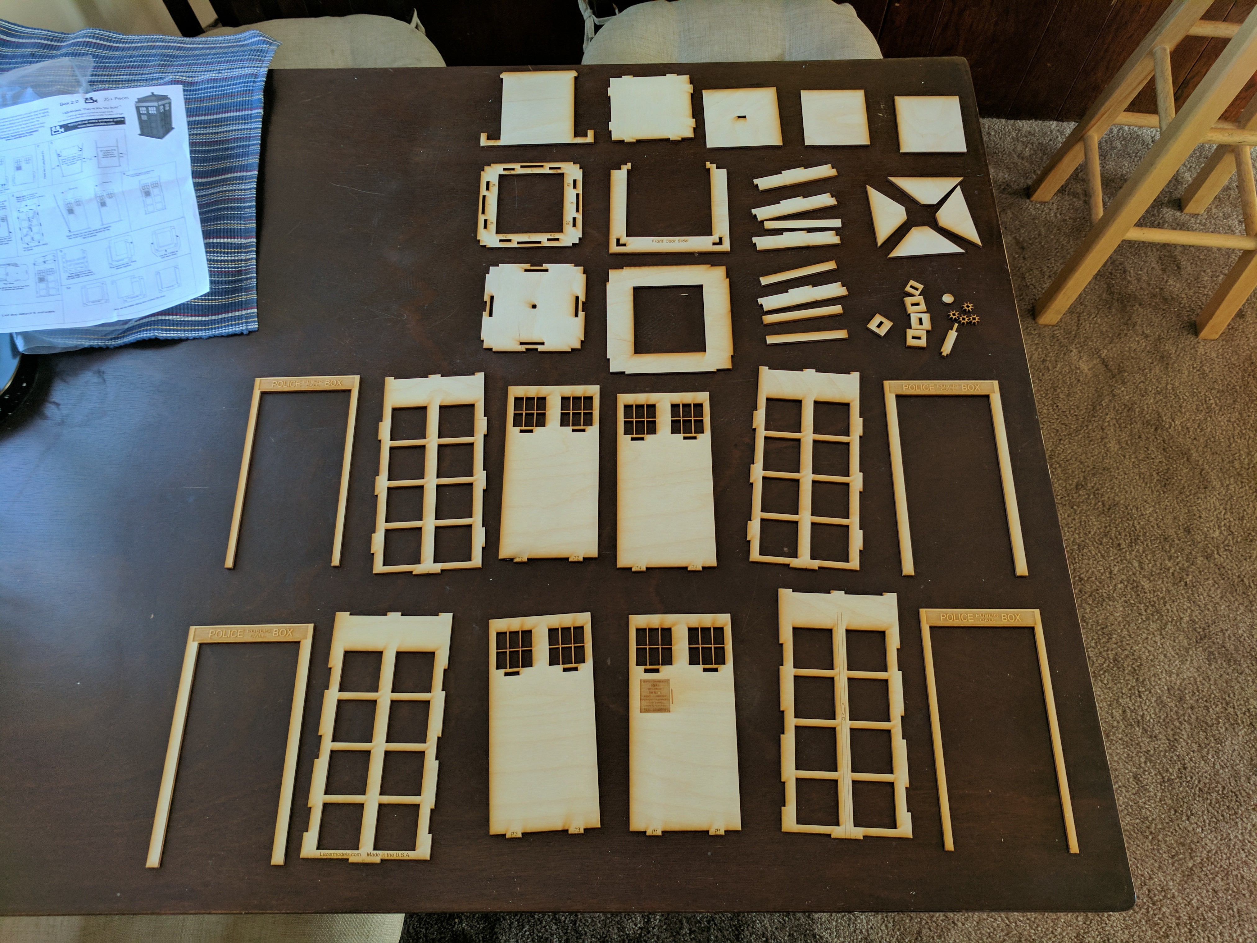
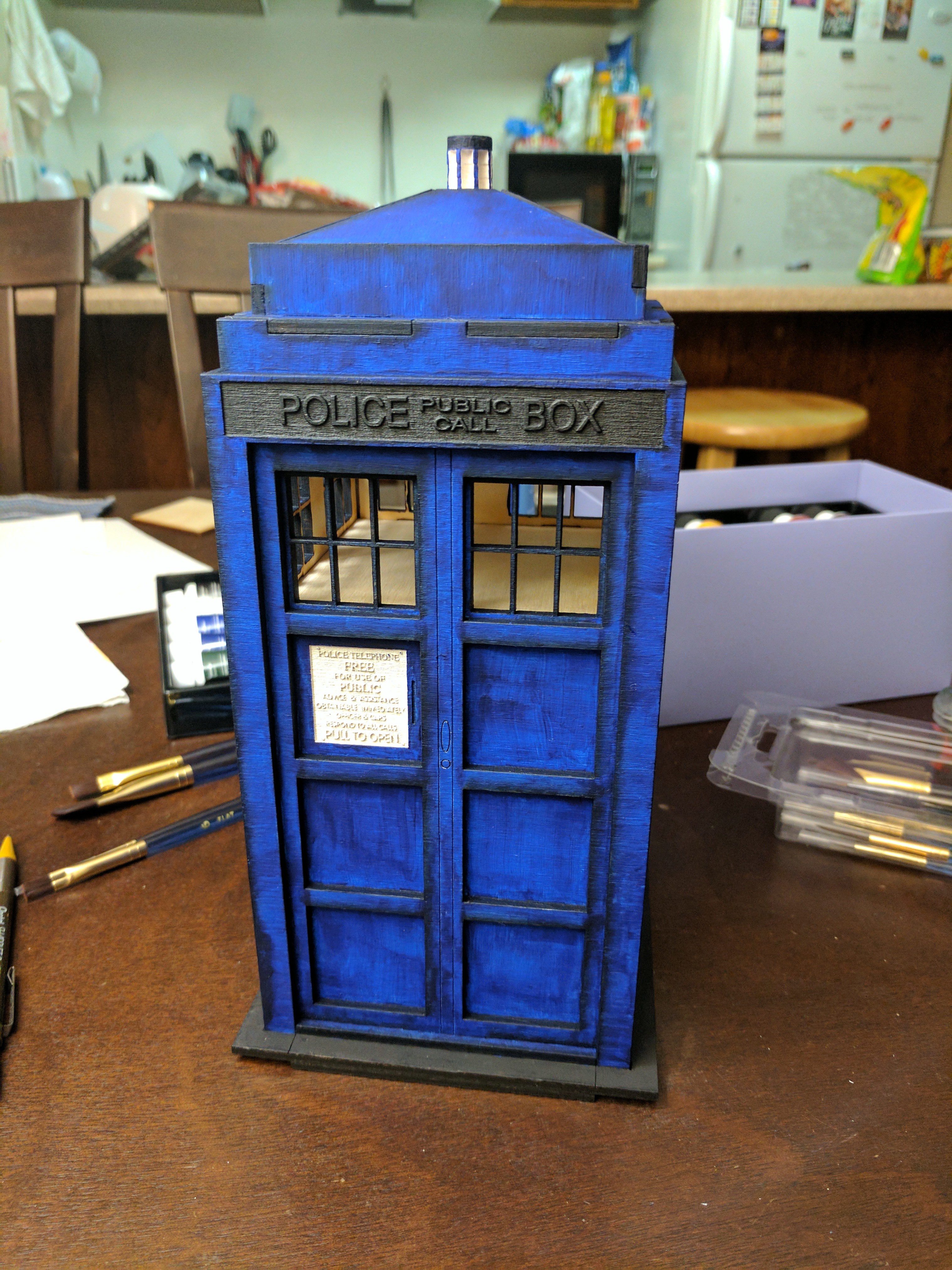
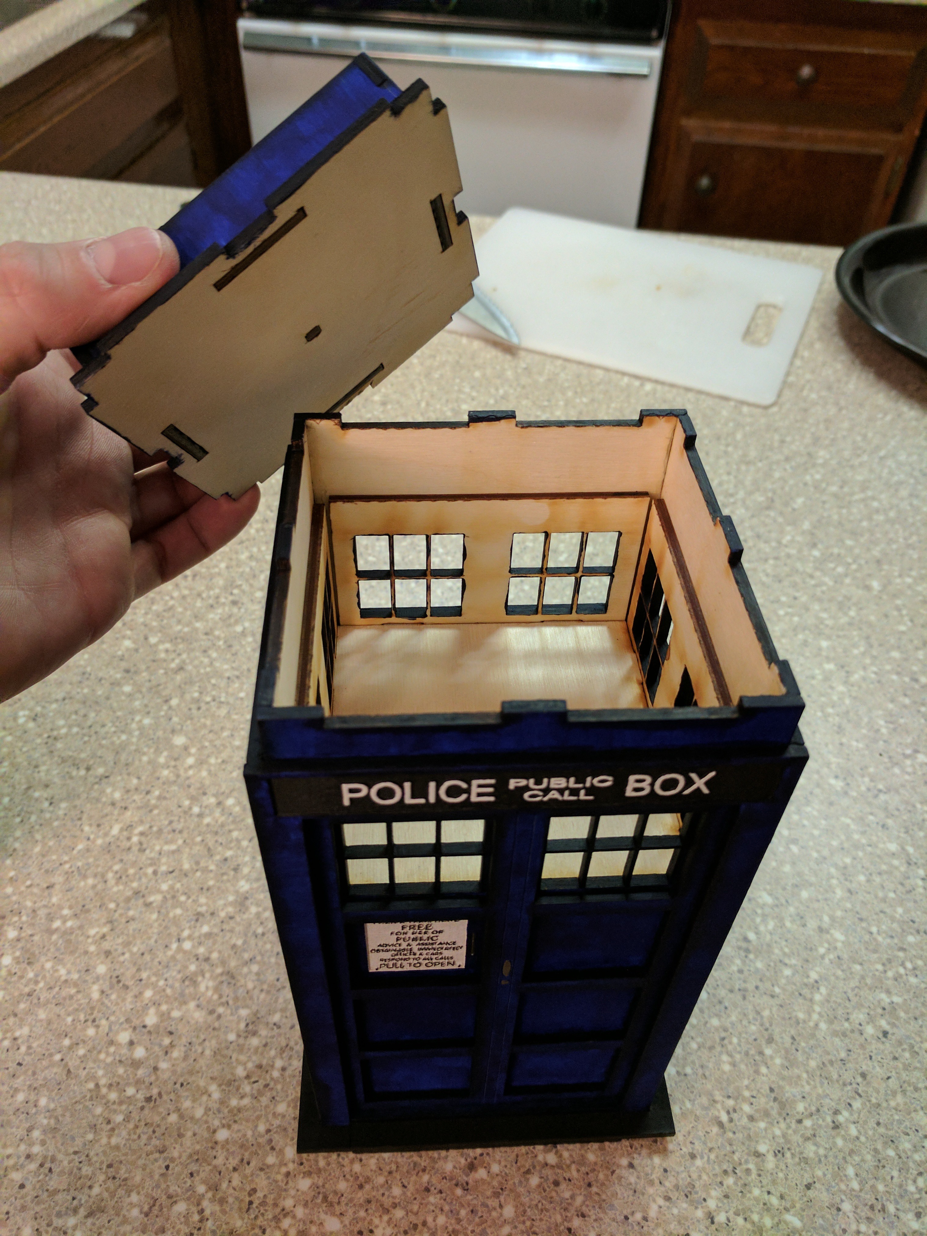
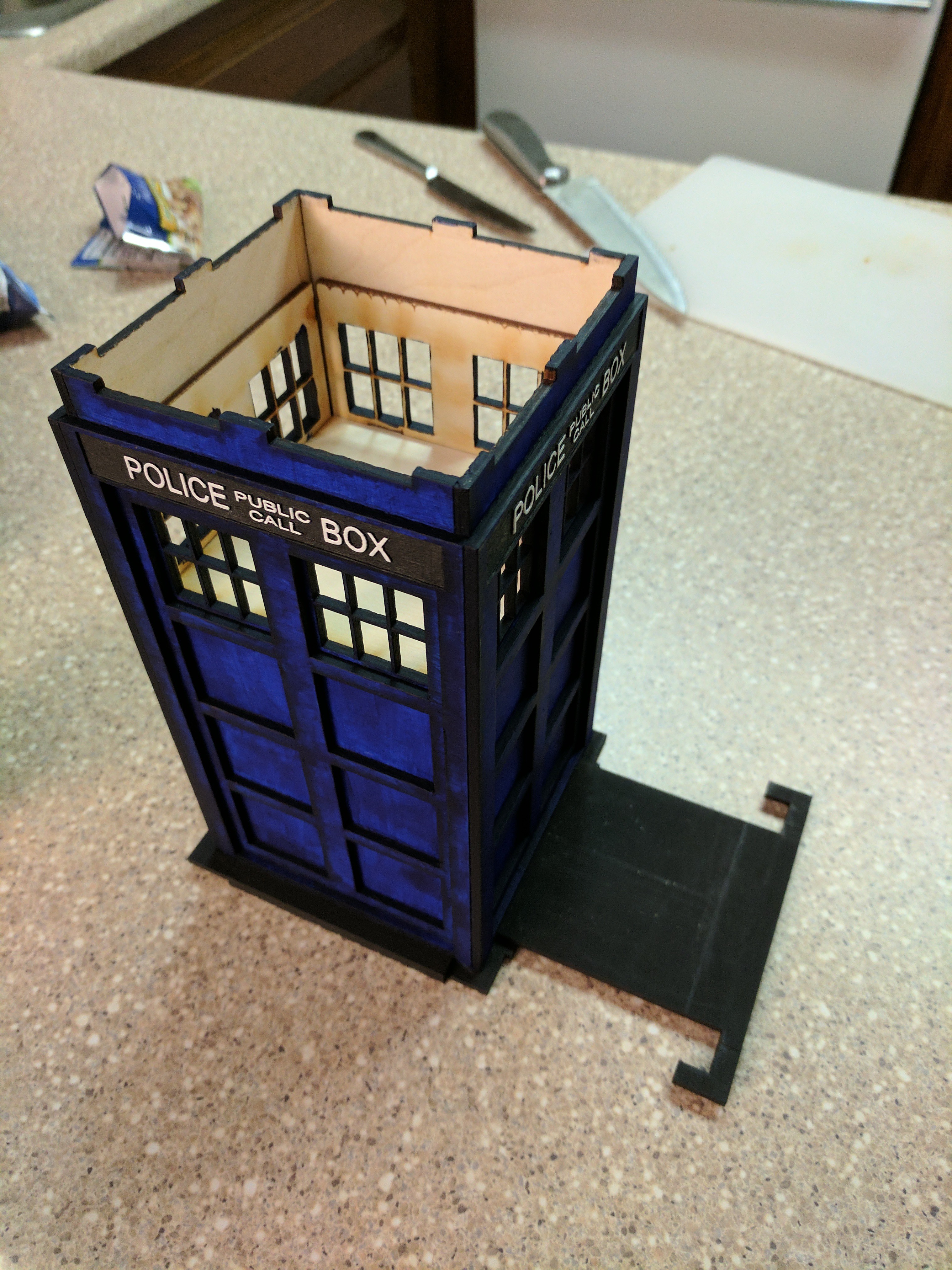
Assembling the Wooden TARDIS Model
The TARDIS model is made of laser-cut wood, comes with directions, and is actually pretty straight forward and quite fun to assemble. There's a moment or two where the directions might be a bit unclear, but (if you're like me) it's kind of a fun puzzle to solve. The folks over at LAZERMODELS also have an assembly video guide in case you need it.
Note: Remember not to glue the roof of the TARDIS on because you'll need to be able to open the top to insert/remove the lights and electronics.
Painting the TARDIS
While I thought the assembled TARDIS looked pretty great, the fact that I had seen such a nicely painted model at Fiesta Hermosa left me wanting more out of this TARDIS.
Now, I'm definitely not an artist (I consider myself artistically challenged), but painting the TARDIS seemed like it should be pretty straightforward.
"It's almost completely blue with a little bit of black and white thrown in for the lettering. How hard could this be, right?"
Despite that confidence, I tried to lower my own expectations since I knew that:
- I can't really paint
- My paint job wouldn't look as good as the painted model I saw at the stand
"Worst case scenario, I can just buy another model and assemble it again. No big deal..."
The other aspect that drove me to paint the model was the fact that I had painted my first painting the weekend before this and it turned out WAY better than I had expected.
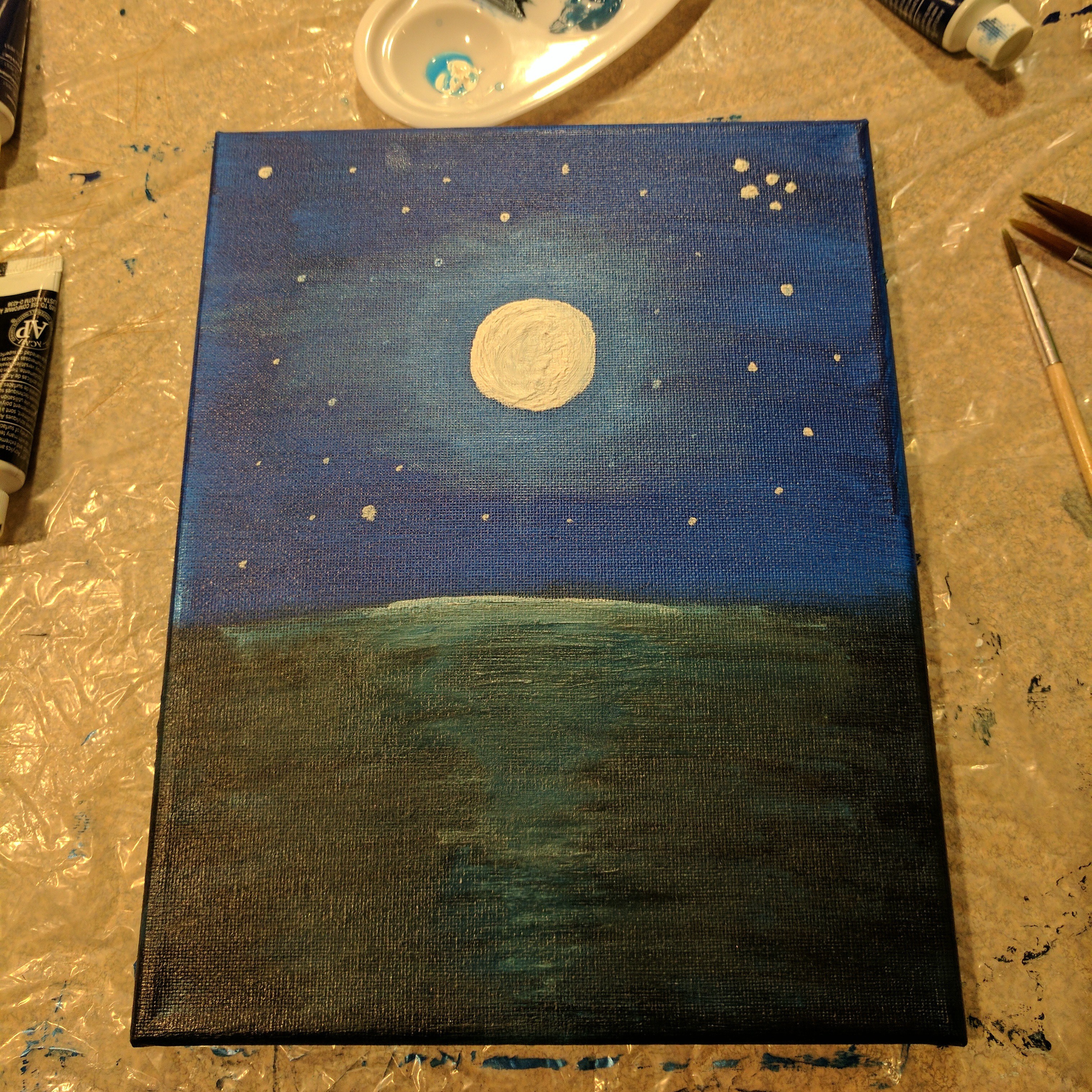
My first painting ever and I'm pretty damn happy with how it turned out.
Maybe I CAN paint!? (Let's not get ahead of ourselves...)
Again, the folks over at LAZERMODELS have a painting video guide for the TARDIS. I always think videos on artistic stuff will help me, but they usually just serve as a reminder of how little I know about the art of... well... art. (I'm looking at you, Bob Ross!)
So, with standards sufficiently lowered, I ran over to Michaels, bought some paints and brushes, and got to painting!
Ideal Painting Tip #1: Putting a coat of primer on wood before painting it will make it much easier to ensure a nice, even, and smooth coat of paint.
On the flip side, I kind of wanted the paint to be a bit uneven and maybe have some of the wood grain to come through, so I skipped the primer.
Reality of Painting #1: I forgot about the primer when purchasing paints and I'm impatient, so I just started painting. (Leave me alone! I do what I want!)
So is it time to begin yet?
Ideal Painting Tip #2: Before you start painting, apply some paint to any excess pieces of wood/fabric/canvas/etc. to see how the paint reacts, absorbs, and dries on the painting surface.
I'm not sure if it was just my model, but the model actually comes with 2 extra pieces of wood. This is perfect for Ideal Painting Tip #2!
Reality of Painting #2: Thoughts of "What if those pieces aren't extras and I actually need them for something?" and impatience lead you to disregard Ideal Painting Tip #2 and decide to just start painting with the least visible side first and hope things just work out.
So off I went!
I started off trying very carefully to apply an even coat (OCD in overdrive) to the back side of the TARDIS (who looks at that side anyways?). After finishing the back side, I got fed up with that level of effort and I started taking more liberties in painting the other sides. My extreme initial effort didn't actually seem to make much of a discernible difference in quality, so I definitely wasted a bunch of time on that first wall... *sigh*
I then realized that I should probably paint the "POLICE BOX" sign before doing all of the walls since it would be difficult to paint the white inside the blue compared to painting the blue on the slightly higher walls around the white.
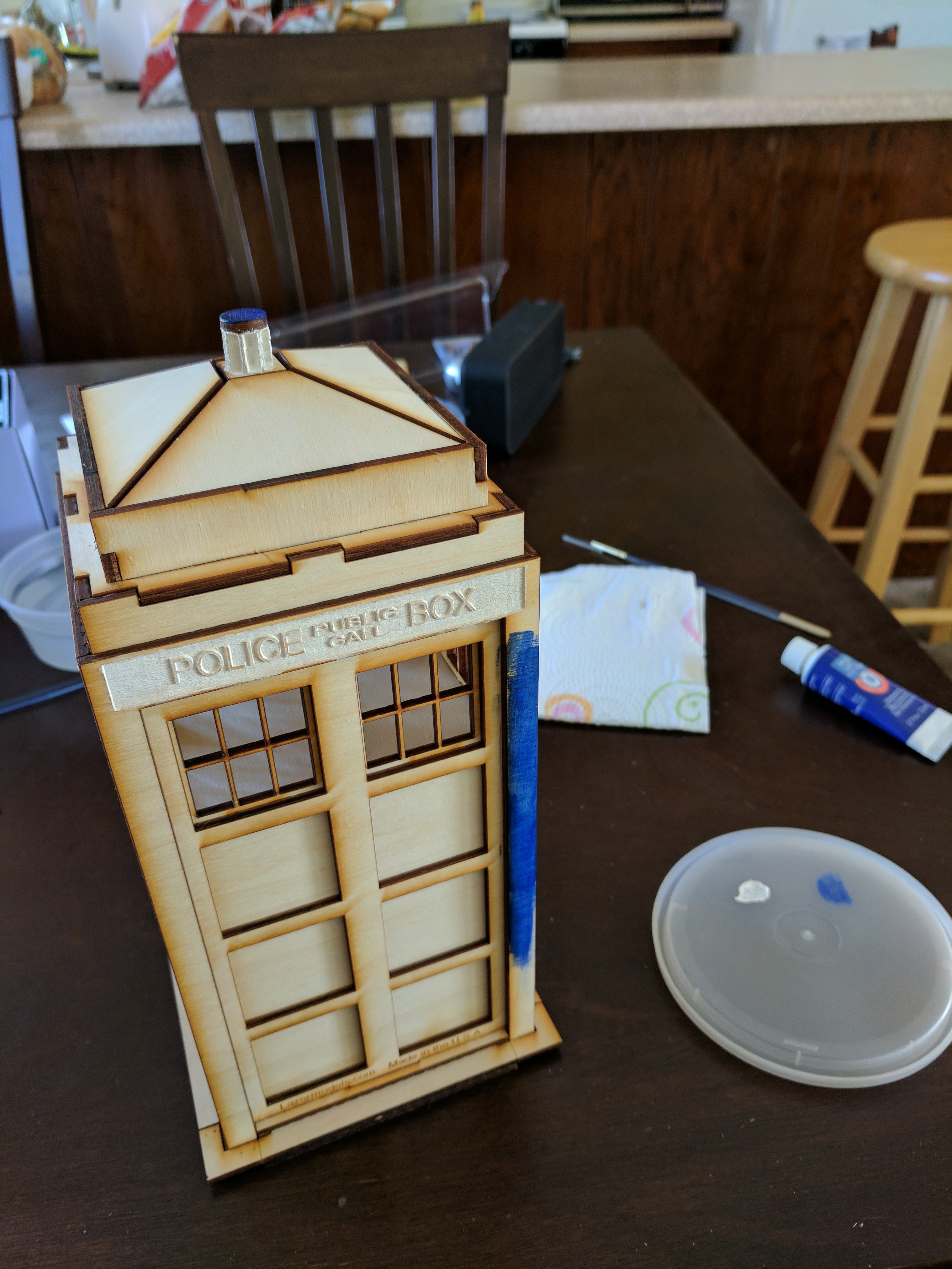
It took me forever to do the first pass on one of the "POLICE BOX" signs because the wood absorbed a lot of the white and it needed several coats to really show as a solid white. The black lettering was much easier and only really needed one coat.
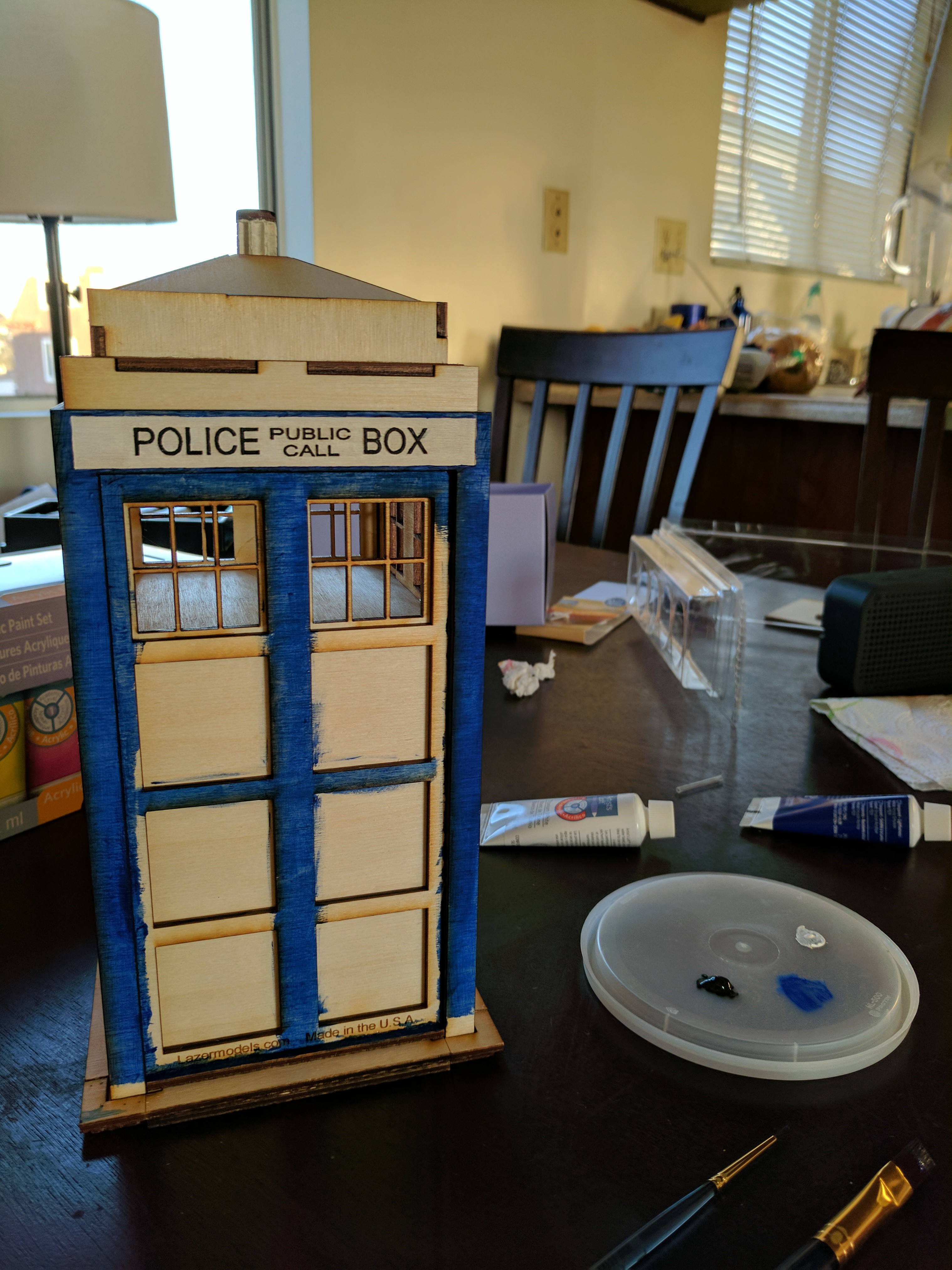
But does anyone notice an issue with the above images?
No?
Let's take a look at the actual TARDIS for a minute...

See it now?
Yup... I got so focused on rushing into painting that I had painted the "POLICE BOX" sign with black letters on a white background instead of white letters on a black background.
Ideal Painting Tip #3: Always check your reference model before painting.
Reality of Painting #3: Yes, painting might not be your thing, but stop being so damn impatient and take a minute to double check things before you start! It'll save you a lot of time!
It turns out that it wasn't as big of a problem as I though since it just took a few coats of paint to fix. It's just not fun to realize you've wasted a lot of time on the wrong thing.
From there, I decided to double check everything again before I continued and off I went!
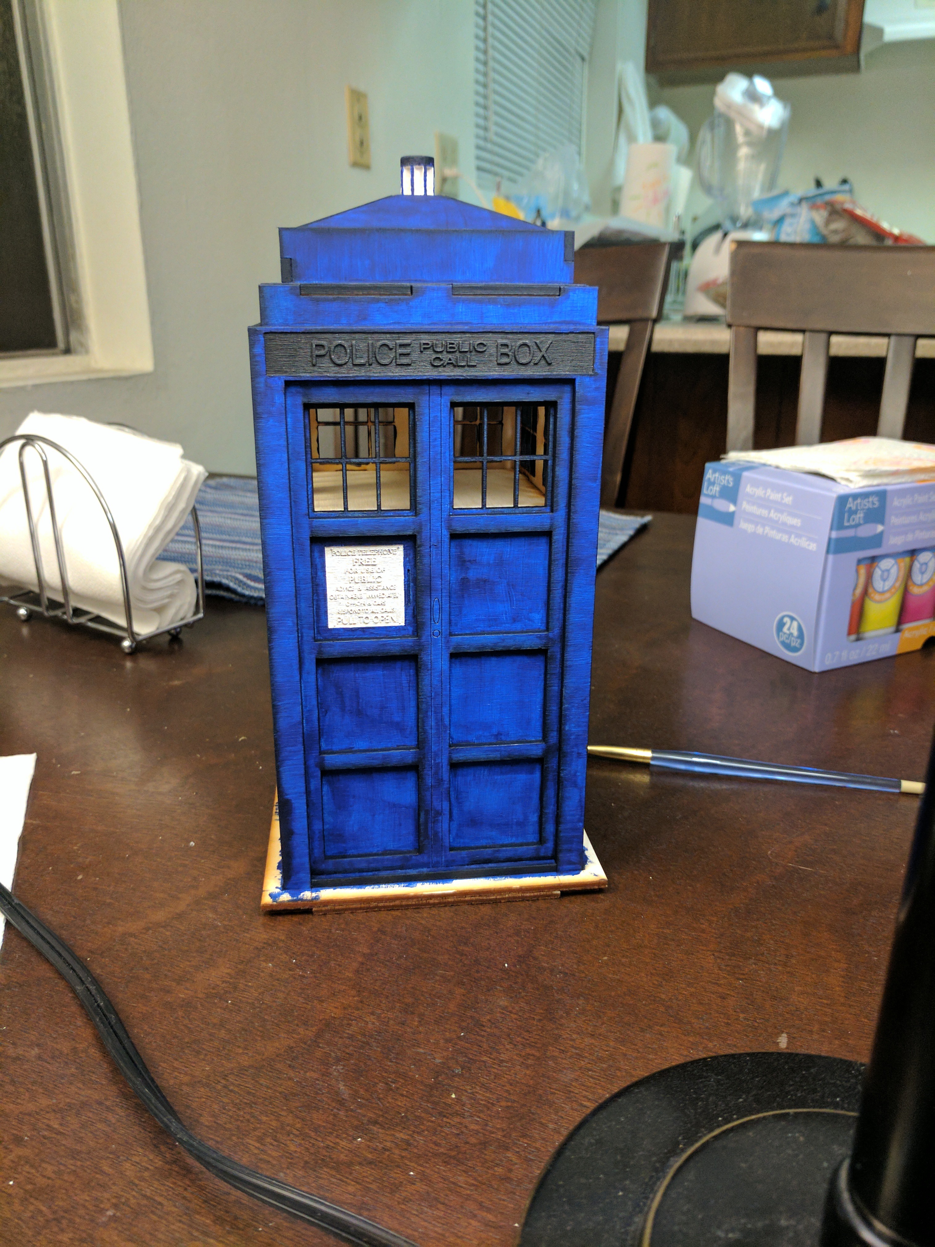
Once the model was painted, I decided I should add a clear coat to seal the paint and make sure the model isn't affected by the elements quite as easily. So back to Michaels I went for some clear coat and vellum (needed for the windows and described below).
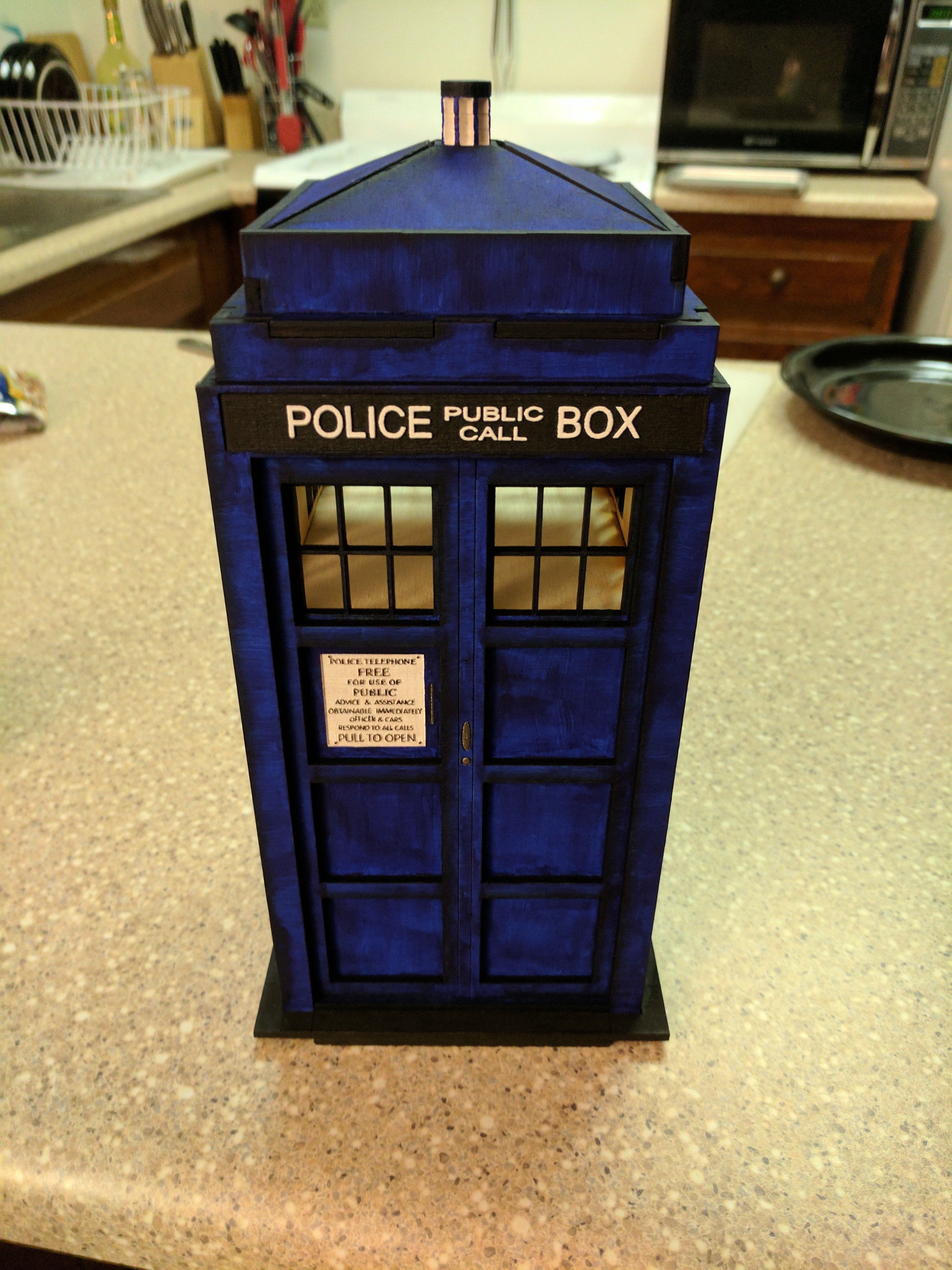
A few layers of clear coat and the TARDIS is all shiny and protected! (A little too shiny for my taste, but I'm hoping that dulls with time.)
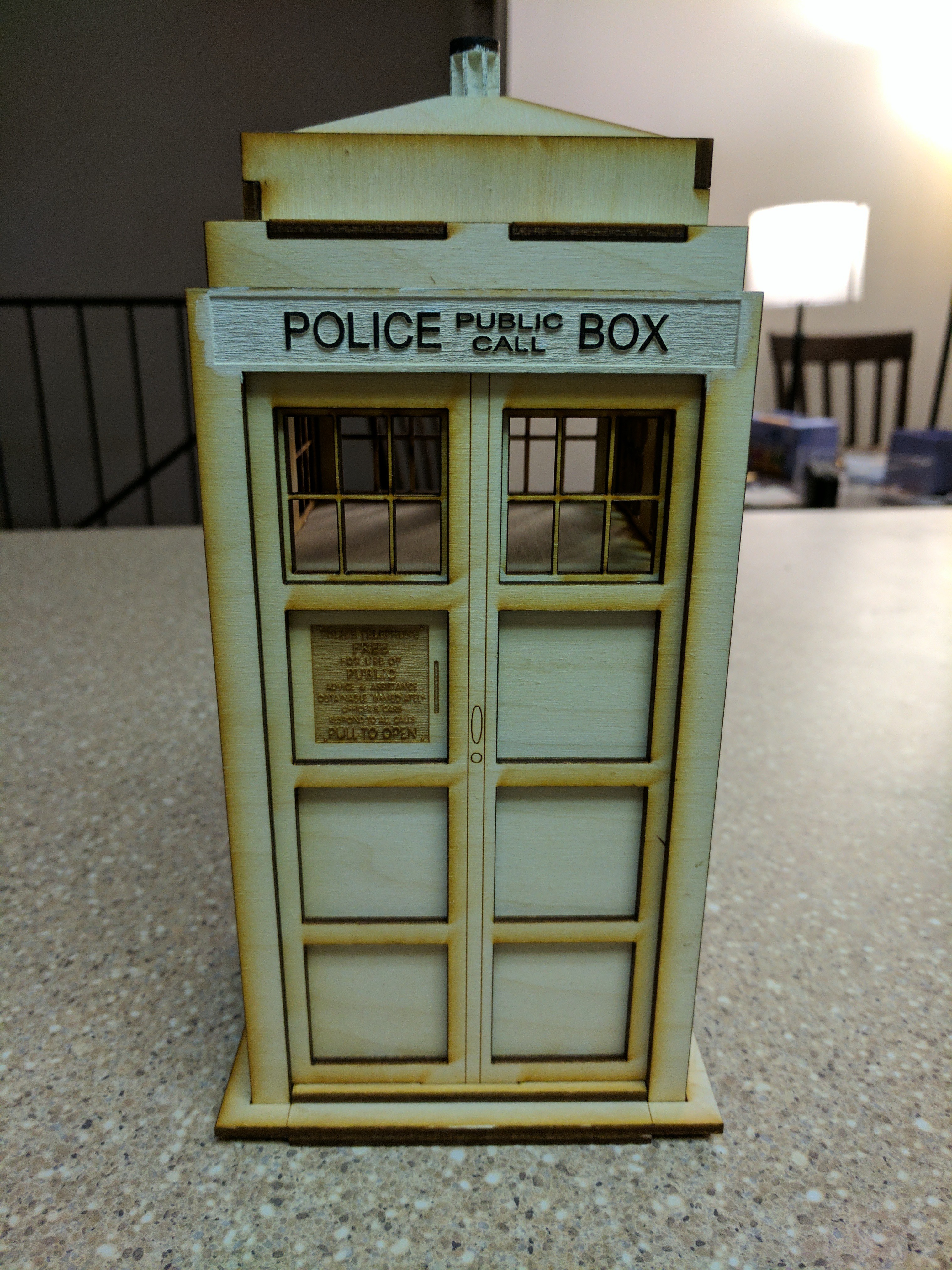
Adding windows to the TARDIS
At this point, I've painted the model, so I might as well add a light to the inside. If I'm going to do that, the TARDIS should have frosted windows so that it diffuses whatever light I put in there.
Again, the folks over at LAZERMODELS have a light conversion guide to guide you through the process if you needed it. Since I'm lazy, I referenced that video to avoid making my own decision on what kind of material would be good for these windows. The recommended material was vellum.
And in the windows went!
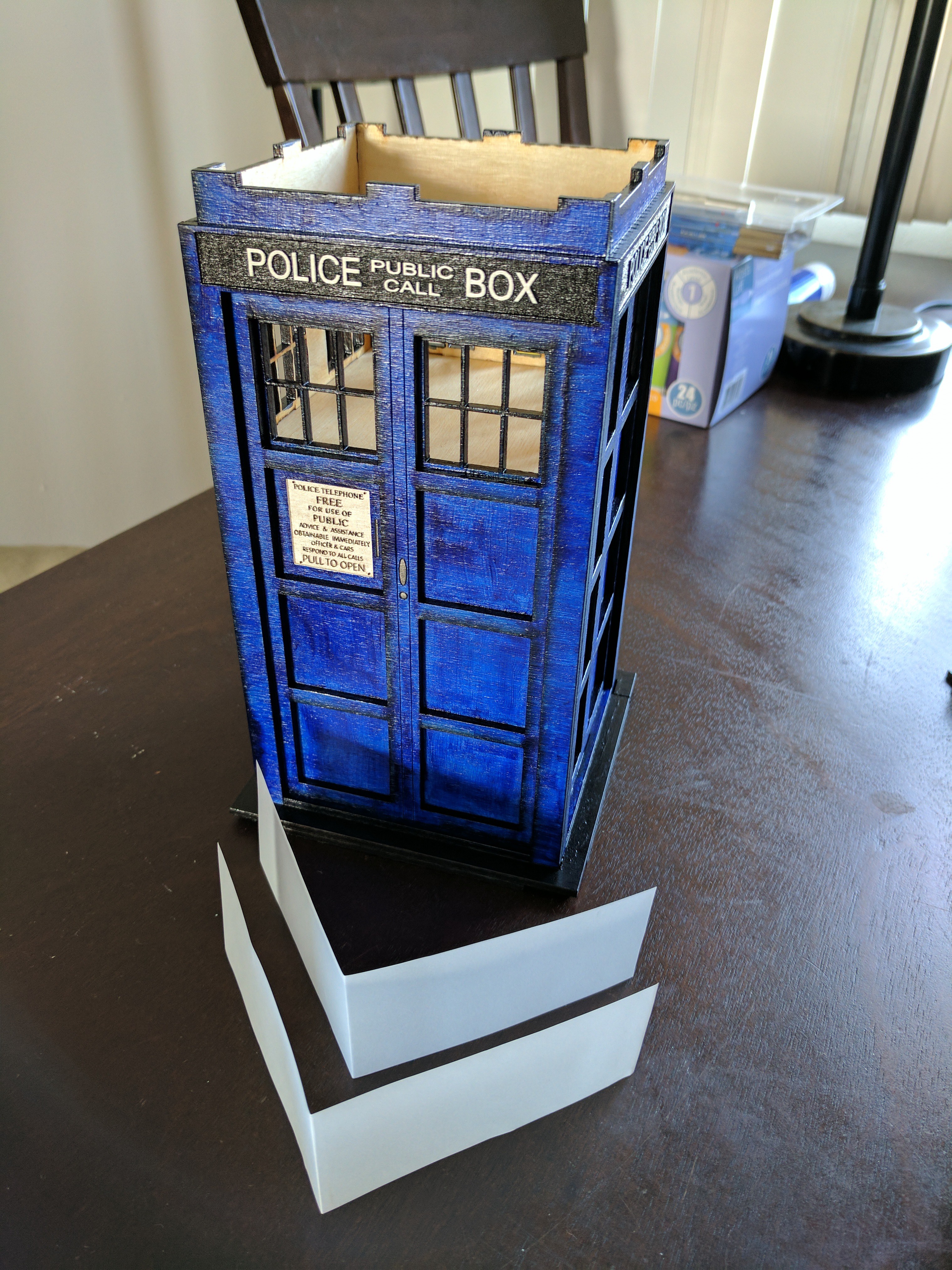
At this point, I was pretty happy with how it looked and I could have easily stopped here.
Well, I couldn't have stopped there, but I imagine others might have been able to...
I used a flashlight to give myself a little taste of what the TARDIS might look with the lights on.
After seeing that, it pretty much guaranteed that I needed to make this happen.
Looking for a simple light to add to the TARDIS
The plan was to find a simple little off-the-shelf LED that would fit inside the top part of the TARDIS. It didn't need to be fancy, just something small that had a little switch that turns a white/yellow-ish light on and off.
I figured one of those little candle lights would be perfect for this, so I looked for this while shopping for the vellum. Even though I found several candle LEDs, all of them would flicker like a candle as well. Definitely not what I was looking for...
Well, if I couldn't easily find something that fit my requirements, I could just make my own little LED circuit (which I've done before). That's not hard. I've done that before.
"But wait, if I'm going to make my own LED circuit, I could also make it pulse like the TARDIS, right?"
Well, shit. Down the rabbit hole we go...
Creating a pulsing LED
A few years ago, one of my coworkers held an on-your-own-time class for people interested in learning how to mess with an Arduino or for people that just wanted an excuse to buy little sensors and play around. I still had the SparkFun Redboard from that class lying around in a box somewhere, so it felt good to finally make some use of it again.
Necessary Steps:
- Build an LED circuit just to make sure I still knew how to do it.
- Pulse the LED.
- Finding the right audio to pulse the LED to.
- This took way longer than it should have.
- It turns out I'm super picky about this. Who knew...?
- Use Audacity to clean up the audio to yield this audio clip.
- Measure the pulse durations in the audio clip and implement a specific periodic LED pulse for each pulse in the audio.
This whole process was far more annoying than it should have been, but that's probably because I was super rusty with each of these steps.
On top of that, I ended up redesigning this algorithm a few times in the end, but more on that later...
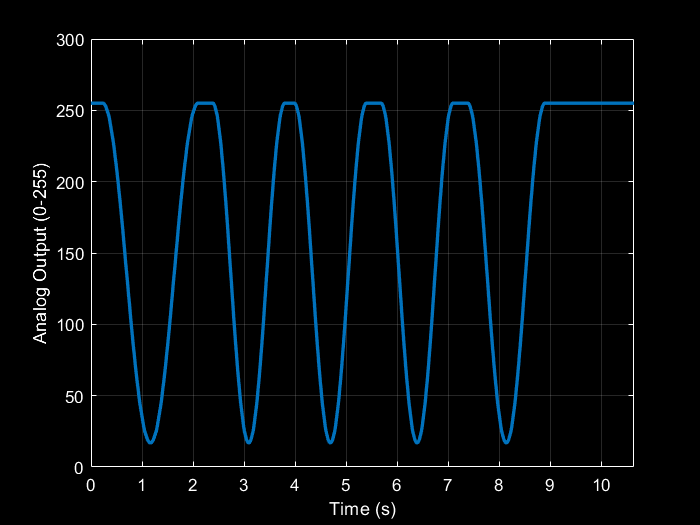
The algorithm I decided on would pulse the LED continuously while making sure that each pulse had a specific period to match the audio.
Here's what the pulsing pattern looks like:
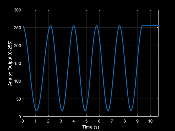
This is a video of it in action:
You can find the Arduino sketch for this at https://github.com/sifounak/TARDIS_Box_Project.
I was pretty happy with this result (for now) and decided to move on to building an actual circuit for the LED.
Building the LED array
Now that I had successfully prototyped the pulsing light, I could actually build a semi-permanent version of the LED array.
Based on my tests with shining a flashlight into the TARDIS, I realized that I definitely didn't want white LEDs. The flash light made the light inside the TARDIS too unnaturally white when it was supposed to be more of a yellow-ish light. So I decided on warm-white LEDs.
Note: I decided not to use yellow LEDs because I was afraid I would need to many to make the light bright enough since the LEDs would be casting indirect light at the windows.
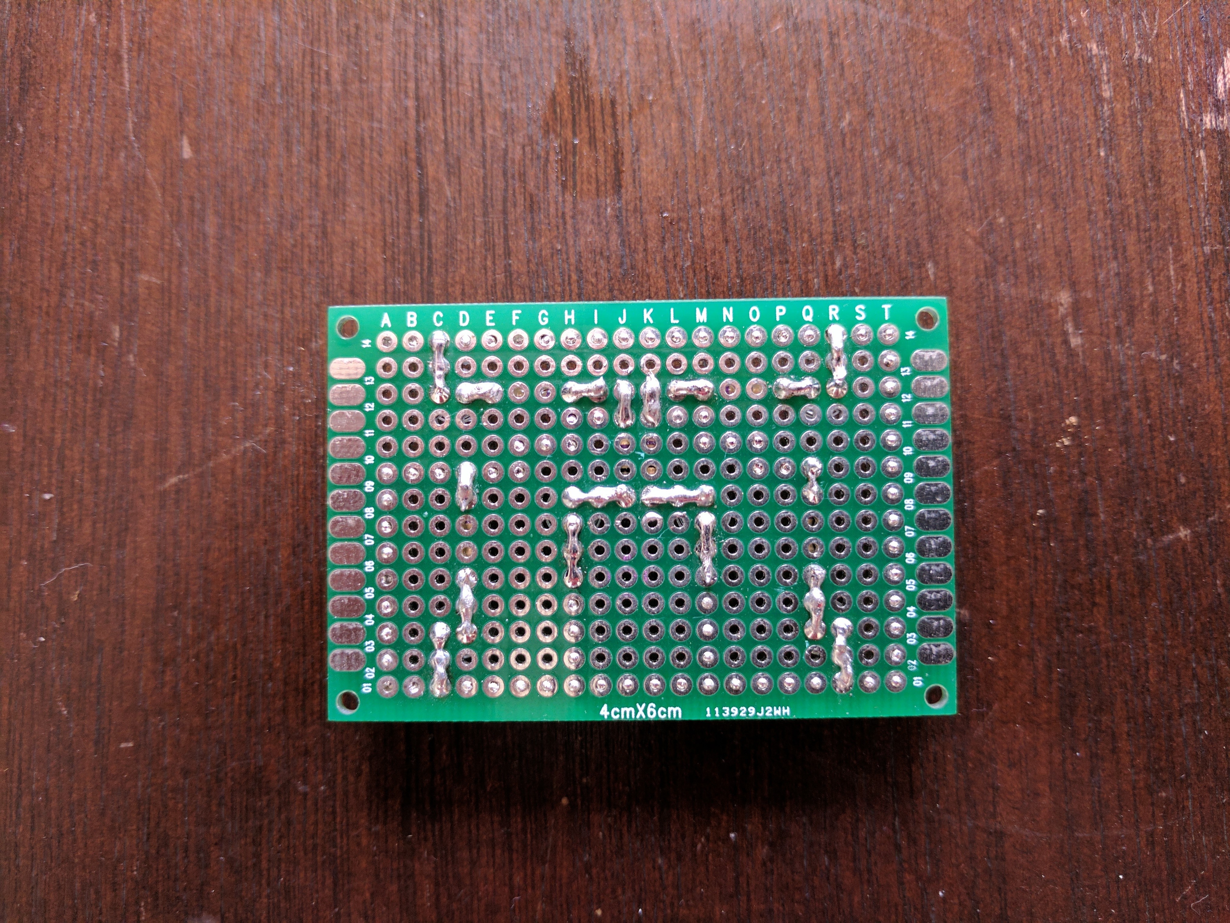
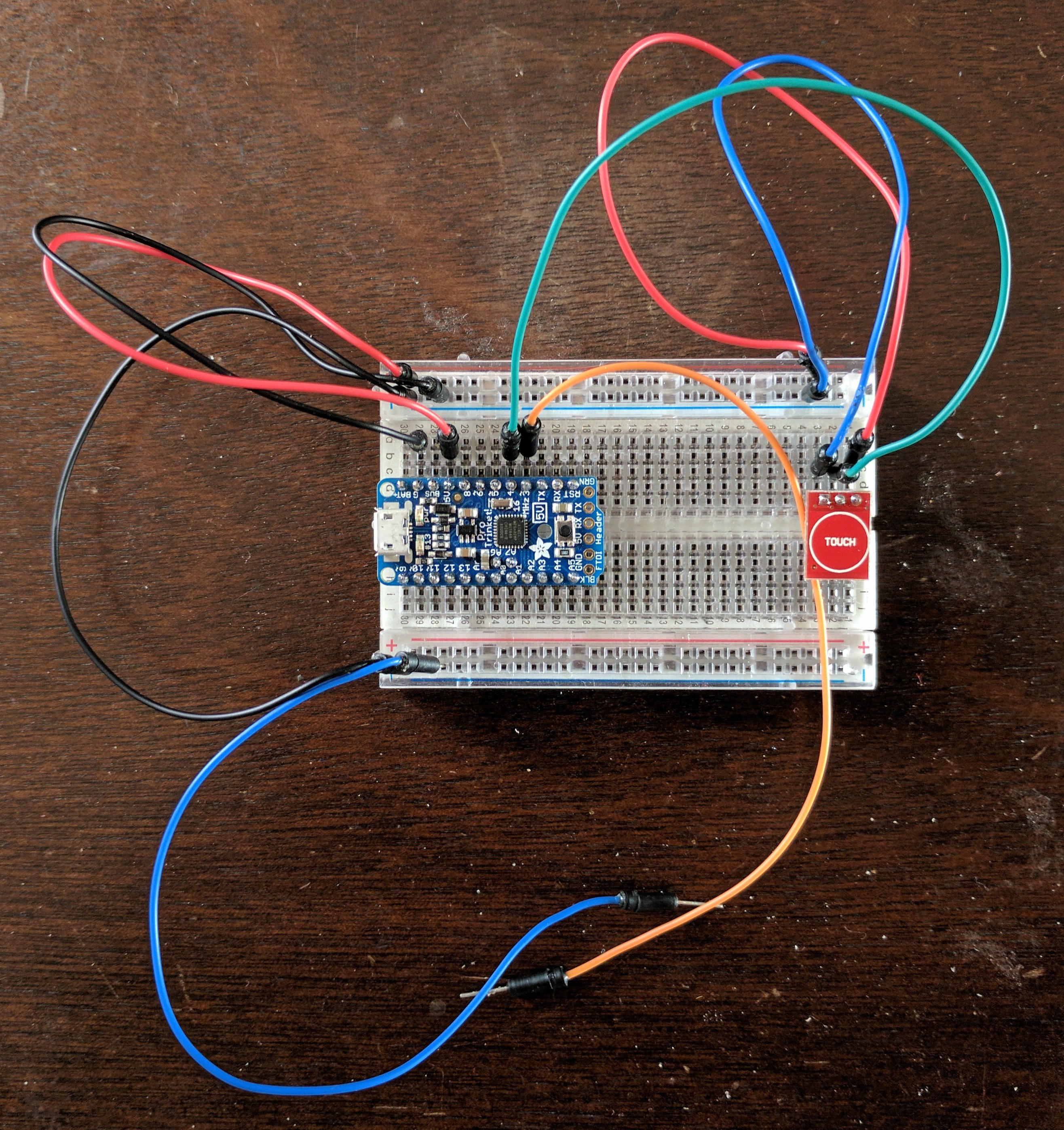
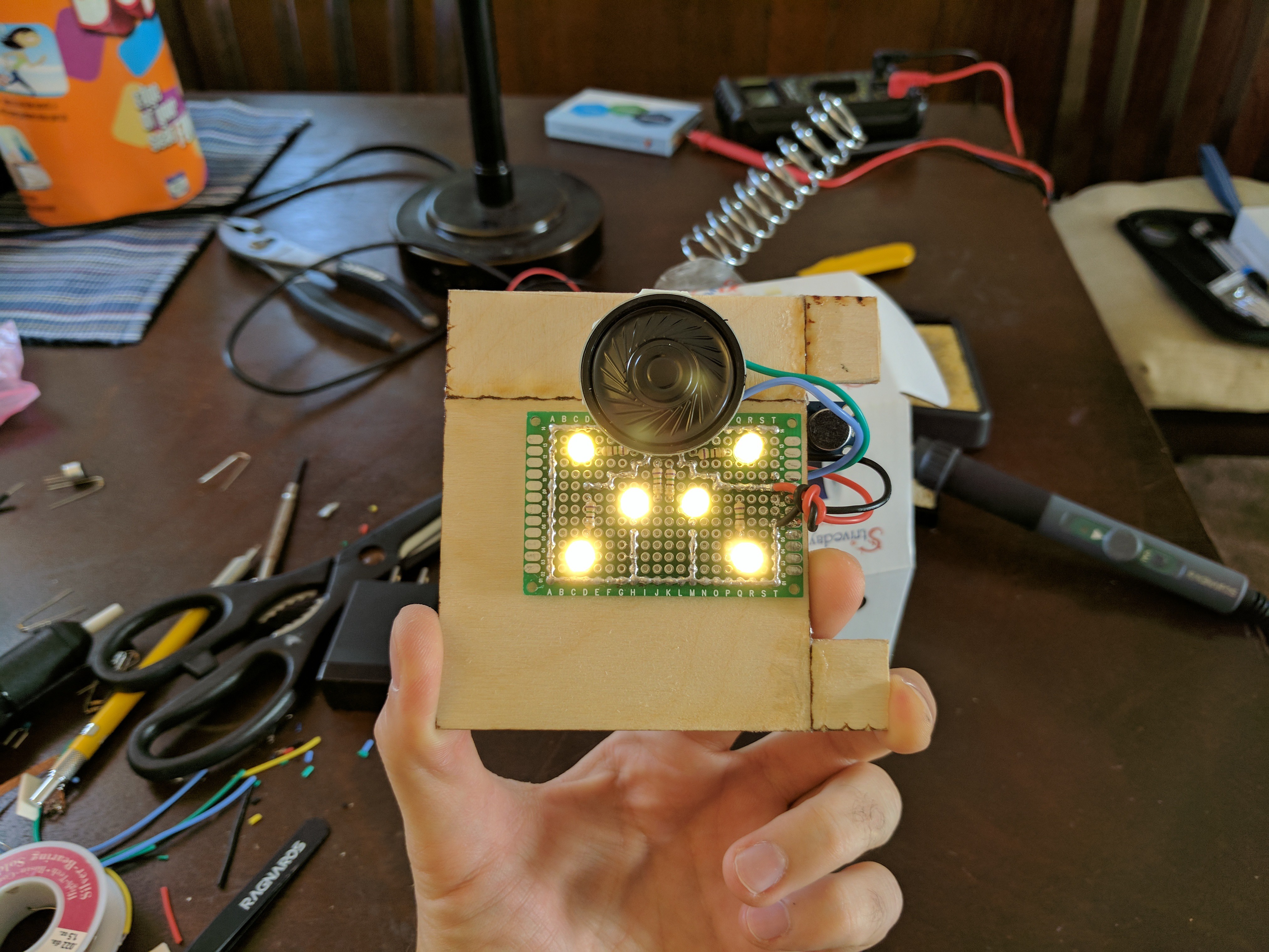
I wasn't sure how many LEDs I should use, so I used a breadboard to test how bright various numbers of LEDS would be. I eventually settled on 6 total LEDs arranged symmetrically (since my OCD really likes design symmetry). I didn't have much extra wire to use yet, so I (impatiently) just created the circuit using the LED leads, the resistors, and an artistically arranged solder bridge.
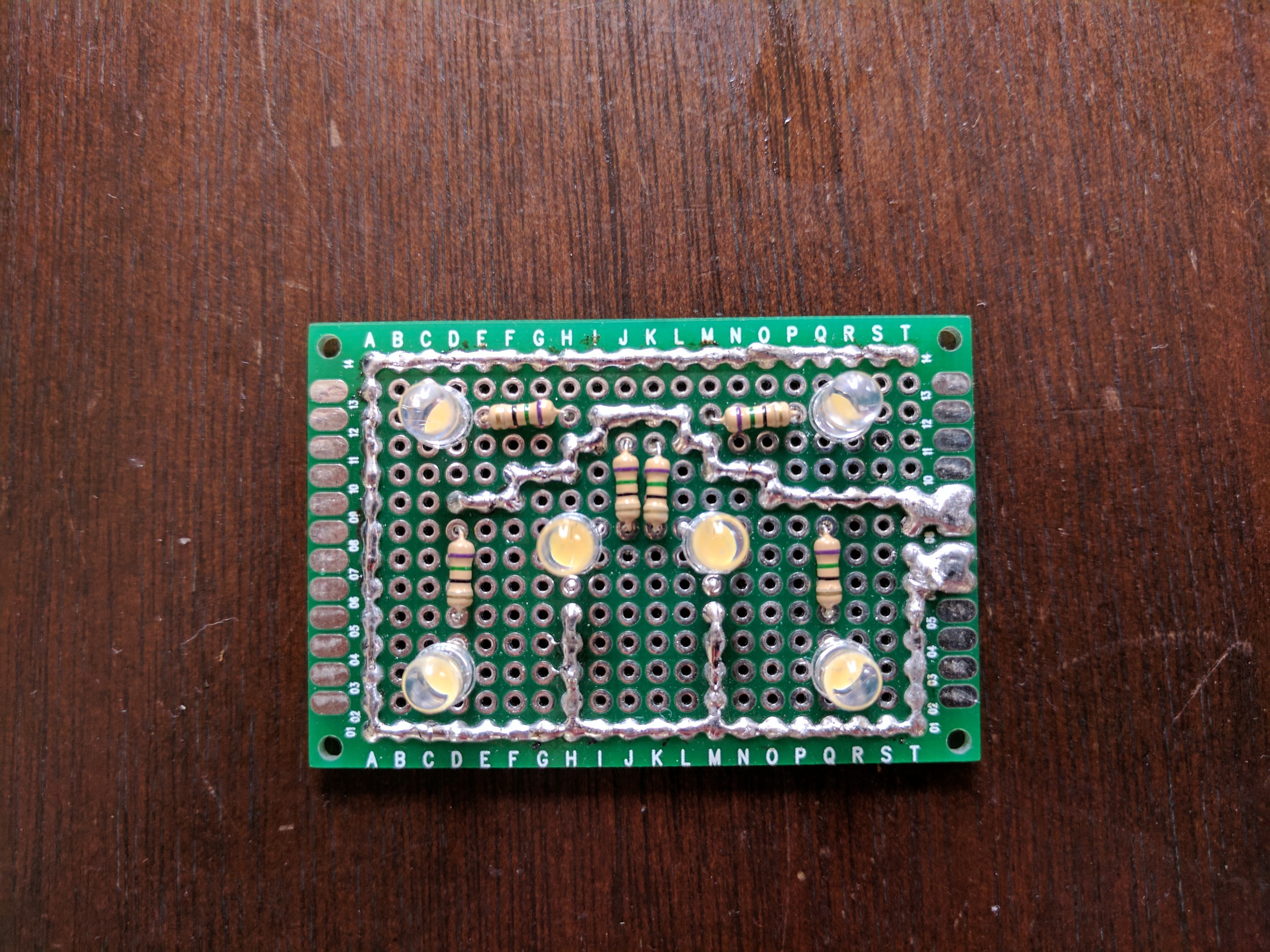
This counts as art, right?
Figuring out the audio board
I had never played any real audio out of an Arduino, so I checked the internet and found tons of ways to do this. Most of the options I found involved buying and assembling separate hardware to decode the audio, amplify the signal, and play the audio through a speaker.
While I'm not afraid to put things together myself (as you might have guessed from the rest of this write up), I noticed that this cost a bit more than I was hoping for and I was concerned that all of this hardware (especially the speaker) wouldn't fit in the box easily. So I kept looking for a cheaper, smaller, all-in-one solution and found this piece of hardware.
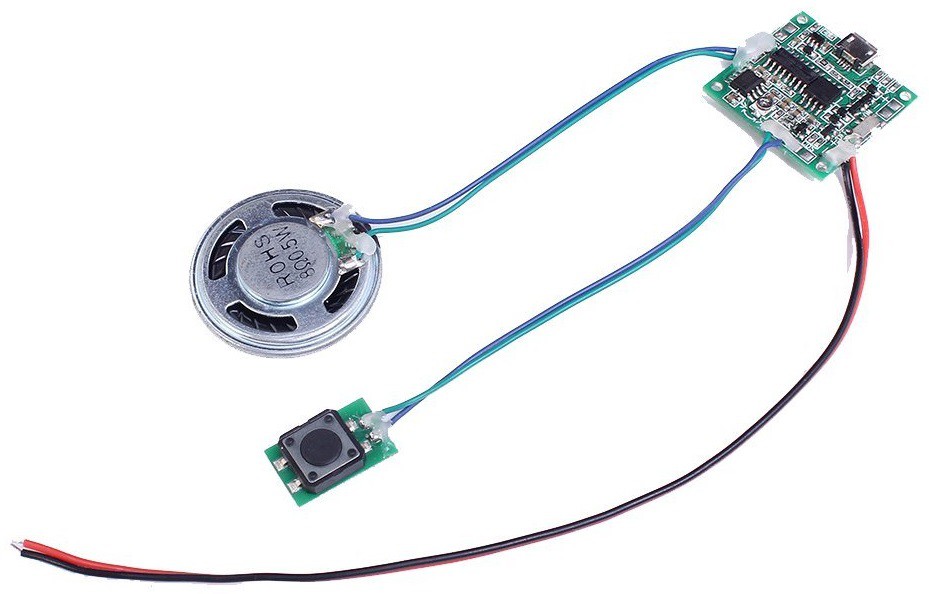
It was simple, had an easy way to trigger it, the speaker looked tiny, there was an on-board way to adjust the amplification, and everything went smoothly (aside from having to wait several weeks for delivery from China and having almost no instructions included).
Steps:
- Load the audio onto the hardware
- This was pretty easy because it shows up as a USB drive when connected to a computer.
- Trigger the audio using the supplied button
- It took a few minutes to figure out that the circuit cannot play audio while it is connected to the computer. *grumble*
- Use the onboard screw to adjusted the volume until I was happy with it
- The screw does not have defined start (low) and end (high) points.
- If you keep raising the volume, it will go to the lowest volume after passing the maximum volume.
Now on to figuring out how to trigger the audio and the Arduino without drilling holes in the model.
Exploring non-invasive ways to trigger the TARDIS
A big requirement I set for myself was to avoid drilling any holes in the model. I didn't want to have wires coming out of the TARDIS or have random buttons/switches sticking out at odd places.
So I kind of narrowed the scope of this search to the following two options:
- Capacitive/proximity touch sensors (ideally triggered through the wood)
- Audio triggering
My initial feeling was to go with capacitive sensors because I felt audio was more inconsistent. A big part of the concern was that I didn't want random noises or loud rooms to trigger the audio, so I would need to put in some signal processing and I didn't want to bother with this aspect.
And this is where the troubles started...
Exploring capacitive sensing
As soon as I tried looking up capacitive sensors for an Arduino, I found a bunch of neat videos that describe the theory behind capacitive sensing, show examples of how to build capacitive touch sensors (measuring the difference in response times, which isn't what I expected), and even touchless capacitive sensing (super neat!).
I decided to look up off-the-shelf capacitive touch sensors to see if they would work instead of building my own. I saw a video that showed a the TTP223 capacitive sensor being triggered through wood and, for about $3, I bought a pack of 10 of these. I was super excited when these arrived, but quickly lost my excitement because of how the logic was implemented on the circuit. The hardware had a "trigger" port that would go high whenever a "touch" was detected. However, it automatically determines what the threshold for this "touch" is when the circuit first powers up. This means that the threshold could be different every time I would power up my circuit (depending on whether something is touching the box or if the lid isn't on exactly the same) and it wasn't something I could consistently control. And, most of the time, I could trigger the sensor by getting close to it and not by touch.
Not cool...
So I decided I should probably build my own sensor. I figured I could put a small, foil strip on the back lip of the TARDIS roof that could be used to trigger the Arduino. It would be small, inconspicuous, and might actually look nice.
After running a few tests on this, I quickly realized that once the foil is attached to the wood, the wood acted as a stronger capacitor than I had expected (which should have been obvious) and it became hard to detect the added capacitance of a normal touch.
It's doable, but kind of a pain.
On top of that, I also set another constraint for myself that made this approach even trickier.
I wanted to be able to easily remove all of the electronics from within the TARDIS so that I could recharge the battery (it's going to be a rechargeable battery, right?). This makes it tricky to have a sensor that's attached to the body of the TARDIS but connected to the removable electronics without requiring me to unplug/plug things every time I needed to recharge the circuit.
Again, it's doable, but it's tedious, more prone to failure from wear and tear, and it might suffer from unstable connections.
So I guess it's time to investigate the audio option...
Attempting to build a microphone
As usual, I started with looking up microphones for Arduinos online and ran across a variety of options. I noticed a bunch of references to an electret microphone and remembered that I had one of those lying around in a box of components I had collected over the years.
It seemed like all that needed to be done was to properly amplify the signal coming out of the microphone before reading it. So, as all rat holes begin, I thought...
How hard could this be?
I started off trying to use an op-amp to amplify the signal. I had used an op-amp back in undergrad a bunch of years ago, so this seemed like it would be pretty straight forward. Unfortunately, I couldn't quite get my gain right. I either ended up with a really low signal or a really high signal because I didn't have a useful range of resistors on hand to mess around with. I could have started creating more elaborate circuits to combine resistors and get the necessary resistance, but I figured I would try something else instead.
Pro Tip: It's nice to have a variety of components on hand when it comes to tinkering because you're never really sure what you'll need during any particular project.
Another option that popped up fairly often is to use a transistor instead of an op-amp. I had never really used a transistor before, but I had always been interested to understand what it specifically did, how it worked, and how I could use one. I followed a few schematics online for electret microphone circuits using transistors, but ultimately ran into the same problem as before: I wasn't able to get a measurable fluctuation from the electret microphone.
Side note: If anyone has any good references for transistors and their usage, I would love to get pointed in the right direction.
Another aspect to consider was that maybe the microphone I had was broken. I just didn't think it was a path worth pursuing any longer than I already had.
Life Advice: Time is the rarest and usually one of the most expensive resources. Even though building everything from components you already have might seem like the cheapest option, it usually isn't cheaper once you consider your time investment.
I still have trouble factoring in the cost of my own time (especially when I'm tinkering with something I want to learn all the intimate details about), but it's something I've been getting better at with time.
Anyways... At this point, I decided to just buy an off-the-shelf microphone sensor.
Using an off-the-shelf microphone instead
After spending a bunch of time trying to build my own microphone, I decided to buy an off-the-shelf microphone with an adjustable gain.
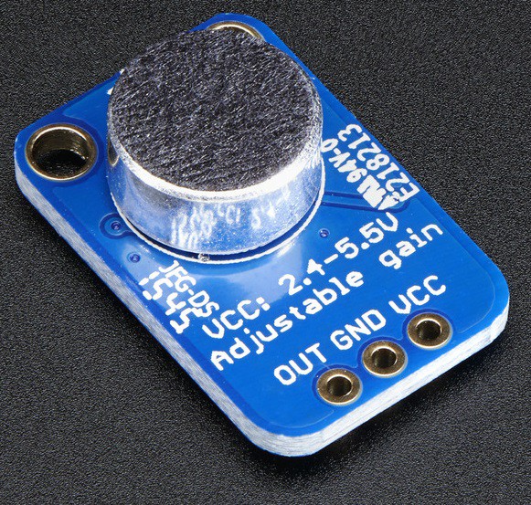
This was such a breeze to work with, especially compared to what I was doing before!
I hooked this up to my Arduino and used the serial debugger to watch as the output changed as I made noise. I used the screw on the back of the circuit to adjust the gain until I could reliably achieve large spikes whenever I clapped or snapped my fingers. I knew I would have to readjust the gain once the circuit went into the box (since the sound profile would change inside the box), but at least the circuit was up and running!
Working with the Pro Trinket 5V
Now that I had some of the big components working, it was time to transition over to the Pro Trinket.
This should be easy!
And, as you might expect, I hit a snag almost immediately.
I had just expected this to work out of the box, but that wasn't the case. As usual, it was mostly because I just made assumptions that weren't true, but I had to do some hunting to figure out what was going on.
Adafruit has a guide that helps you get the Pro Trinket 5V running with the Arduino IDE and it's pretty straight forward. Well, it's pretty straight forward as long as you don't miss step 7 like I did. Ugh...
Steps to get the Pro Trinket 5V working with the Arduino IDE:
- Add the following URL to the "Preferences > Additional Boards Manager URLs:" field:
- https://adafruit.github.io/arduino-board-index/package_adafruit_index.json
- For some reason, I had to restart the Arduino IDE after this, but you might not need to
- Install the Adafruit support package for the Pro Trinket
- Tools > Board > Boards Manger
- Search for "Adafruit AVR Boards"
- Install
- Restart the Arduino IDE
- Install the Windows drivers or setup udev on Linux
- Select the Pro Trinket 5V/16MHz from "Tools > Board > Pro Trinket 5V/16MHz (USB)"
- Select the USBtinyISP programmer from "Tools > Programmer > USBtinyISP"
- Upload your sketch to the Pro Trinket while it is in the bootloader (pulsing red light, this is the only time you can upload a sketch)
- The Pro Trinket enters the bootloader when it first starts up
- To get back to the bootloader at any time, use the reset button
- NOTE: Sometimes it takes longer than 10 seconds for your sketch to compile, so you might need to restart the Pro Trinket just before the sketch is done compiling
Aside from the lack of serial debugging and a different pin arrangement, the Pro Trinket works just like a normal Arduino.
From here, it was smooth sailing!
Switching over to battery power
I got everything working exactly as I wanted it, so it was time to move over to battery power.
"What could possibly go wrong?"
Well, this...
First thoughts:
Well, shit... Maybe this battery wasn't strong enough for this circuit? Maybe I needed the 3V Pro Trinket instead?
Second thoughts:
Well, maybe I'm just drawing too much power at the start and it never makes it to steady state operation.
I figured that adding a capacitor might help resolve this issue because the capacitor would give the circuit little store of energy to draw from during boot.
There are 3 possible outcomes here.
- The capacitor successfully gets the circuit past boot and the circuit stays on indefinitely.
- This means it was just an initial power draw issue. Awesome!
- The capacitor successfully gets the circuit past boot, but the circuit eventually reboots again.
- This means that the power draw is too high for this battery and I might need different hardware.
- The capacitor fails to get the circuit past booting up.
- This means I either did not have a large enough capacitor, I did not charge the capacitor enough, or the power draw is too high. *sigh*
I had a small box of miscellaneous electrical components I had acquired over time, so I pulled out the largest capacitor I had and gave it a go.
The result:
I'm really glad that worked because, aside from an initial power draw issue, the amount of work needed to fix this problem might have been a deal breaker for me to continue. So lazy... Haha!
But am I using the right size capacitor or is this one overkill?
Side note: I keep saying that I'm super lazy, but I keep taking detours like this when I really don't need to. I either need to stop saying that I'm lazy or get my act together and get better at actually being lazy. Anyways...
I figured it would take a non-trivial amount of work to compute just how big of a capacitor I would need, so I decided to brute force this process.
Steps:
- Replace current capacitor with the next smallest capacitor available
- Boot circuit
- If circuit boots, go back to Step 1.
- If circuit fails, the previous (larger) capacitor is the MVP (minimum viable product).
These steps eventually led me to using a 47μF capacitor. Again, I'm not sure if that's the optimal capacitor, but it was the smallest capacitor I had on hand that worked.
Good enough for me!
Redesigning and rebuilding the circuit
As you can tell from the videos above, at some point I had moved from using a breadboard to integrating everything into a protoboard.
Unfortunately, as you might have already guessed from my debugging up above, I had probably jumped to using a protoboard a bit too early and I was unhappy with how my circuit was laid out now that I had to add/change components (added a capacitor, switched from needing space for a capacitive sensor to needed room for a microphone, etc.).
So I did what any sane person would do when they realize that making the circuit prettier doesn't really matter because it's going to be hidden 99% of the time...
I ripped the entire circuit apart and built it from scratch again...
Pro Tip: Determine and test all major components before soldering an Arduino-like IC. Trying to unsolder 16+ pins at a time with just a soldering iron is NOT easy.
*sigh*
So the circuit went from this:
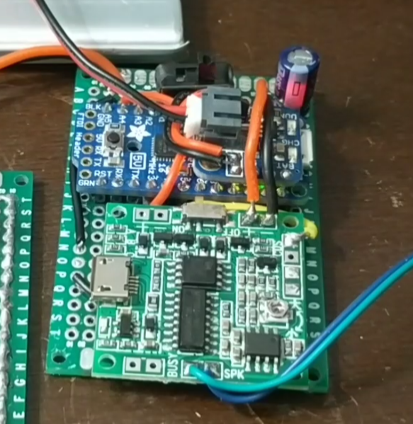
To this:

And, finally, to this:
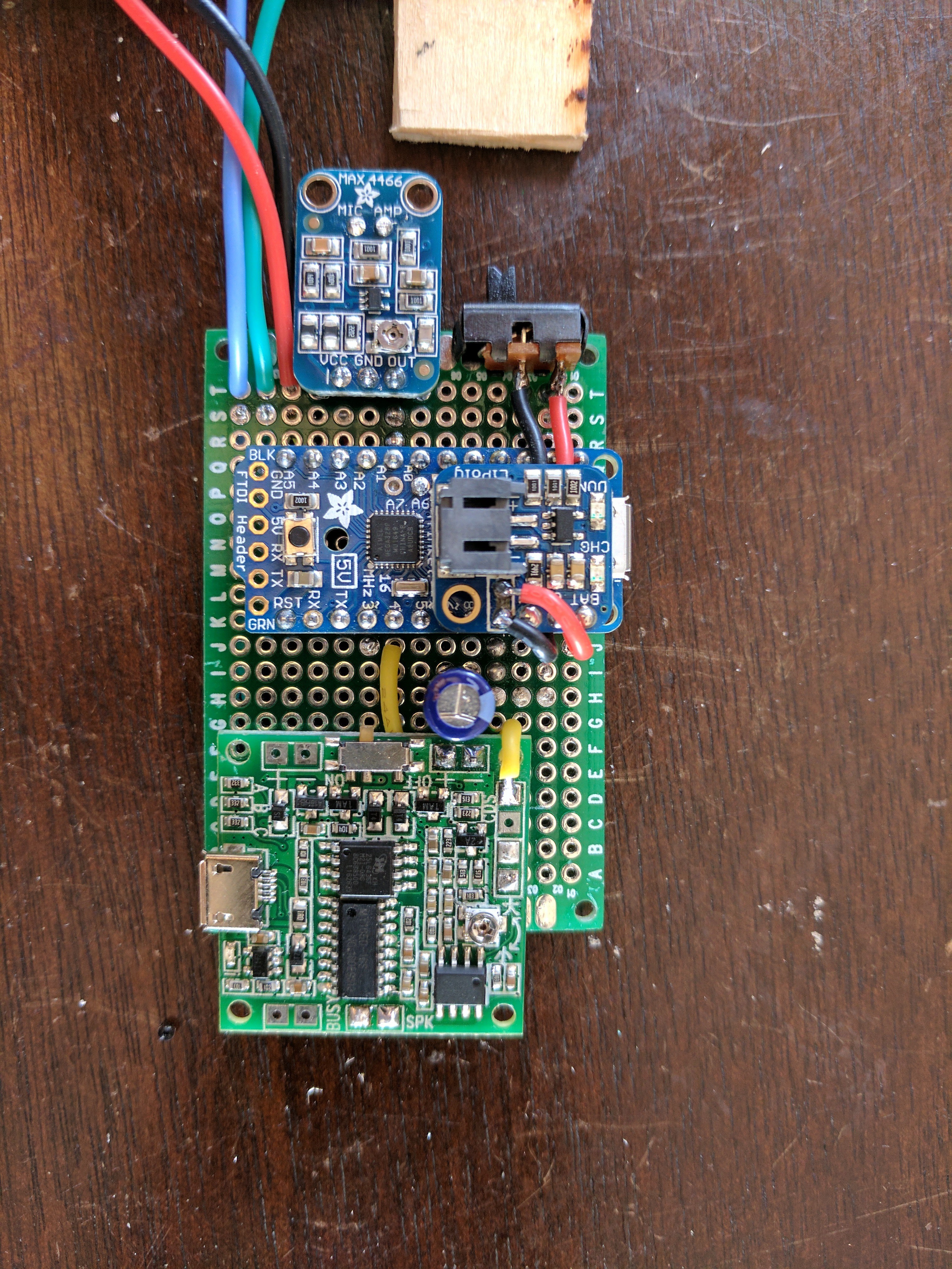
As much of a pain as it was to break that board apart, the end result looks quite nice, the connections are all more stable/robust, and I got a bit more practice soldering and desoldering components (man was I rusty...).
The circuit looks like this:
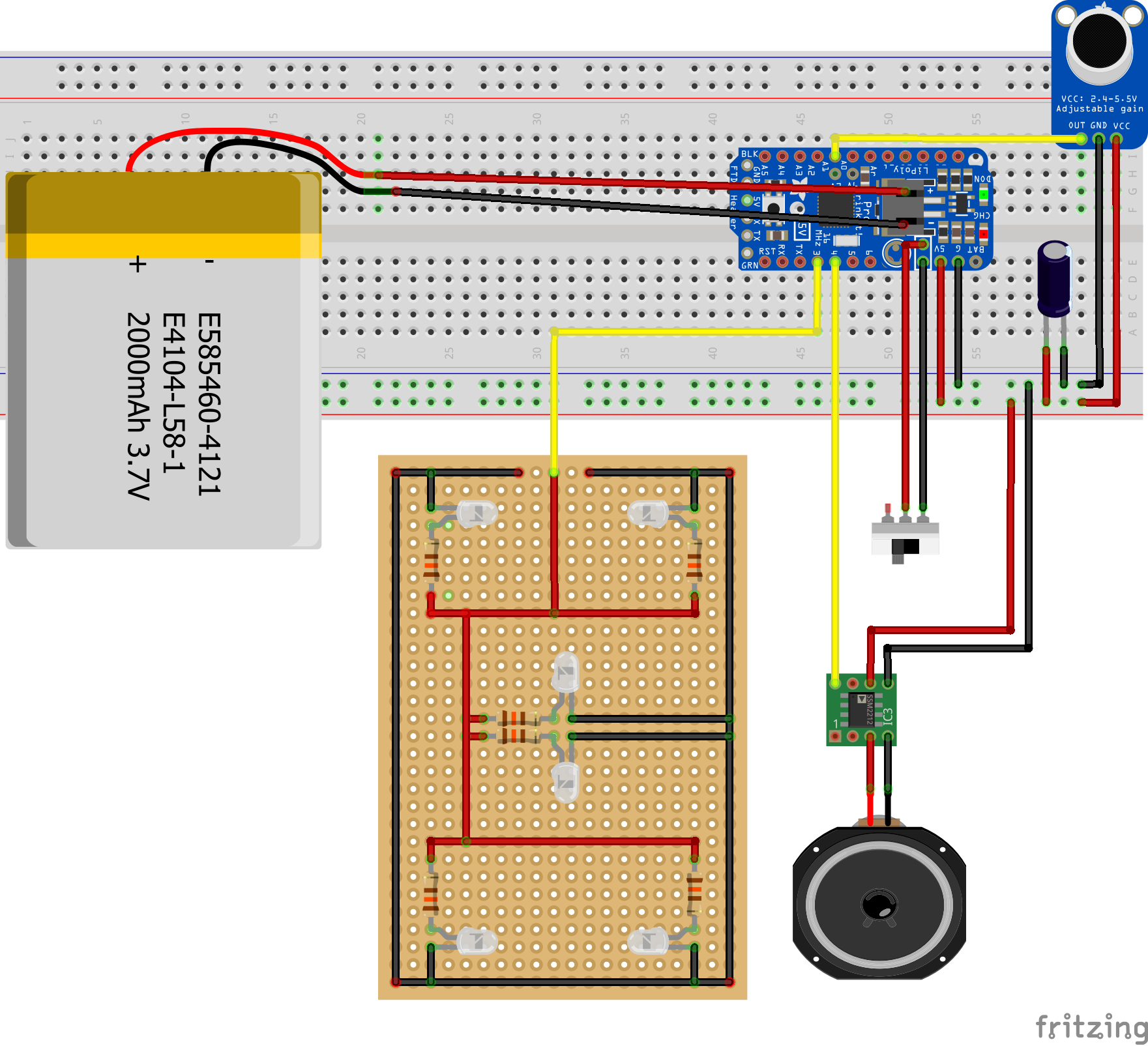
Note, the little green PCB is a representation of the audio board since there were no fritzing files available for that specific board.
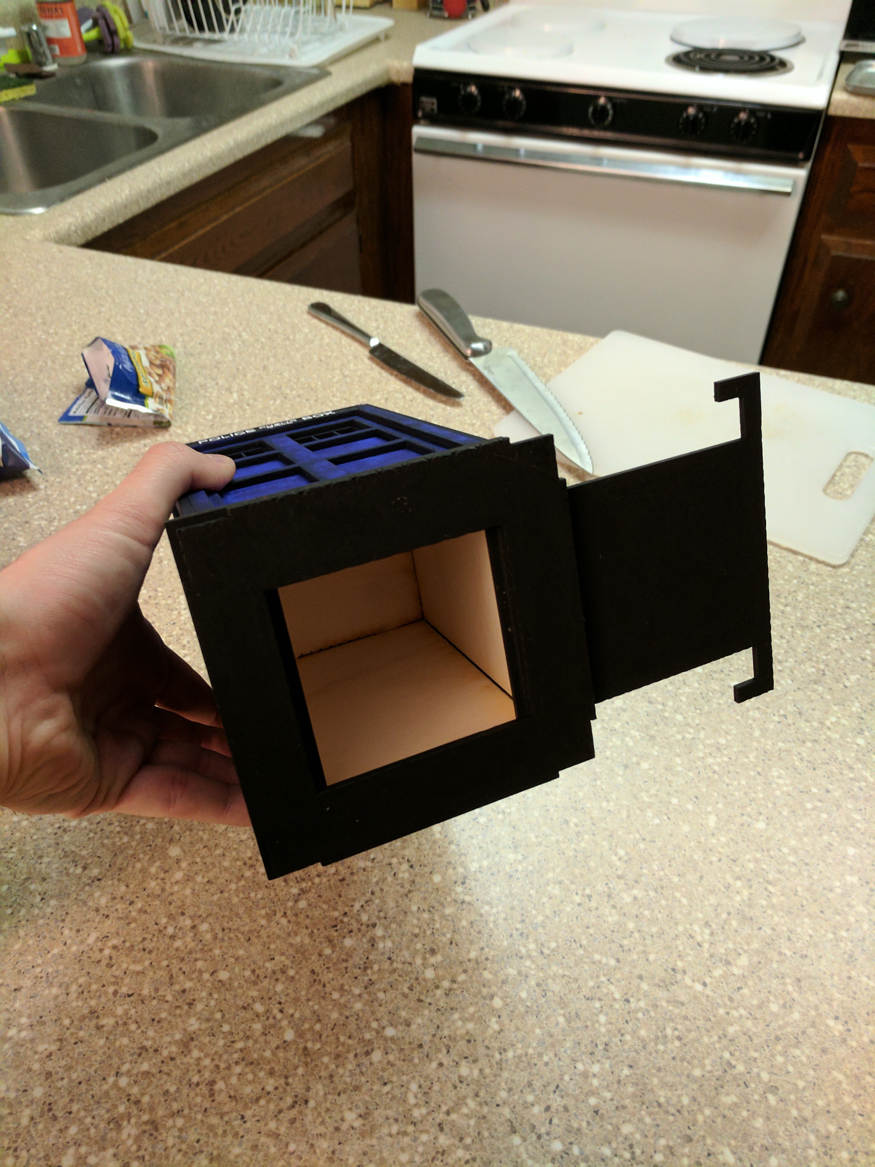
Mounting the circuit, lights, speaker, and battery
Now that I have pretty much everything working, it was time to get all the big parts mounted onto the wooden board!
Remember those 2 extra pieces of wood I talked about earlier? The pieces that I probably should have used to test the paint on?
Well, those came in handy!
Suck it, Ideal Painting Tip #2!
I could mount the circuit and battery on one side of a piece of wood (this side pointed up) and the speaker and LED array on the other side (this side pointed down towards the TARDIS windows).
One major problem: The extra wooden pieces don't sit flush with all of the lips and walls within the TARDIS' top cavity.
Problem detail: The TARDIS model has a small lip about an inch below where the roof sits. The lip runs all the way around the inside of the window area and is just out of sight of the windows (which is perfect!). But each of the two extra pieces of wood are wide enough in one dimension to sit on the lip, but cannot not reach the other lip along the other dimension.
Why is this problematic?
- Every time I remove the circuit to recharge the battery, the piece of wood would need to be returned really carefully to avoid having it fall off the lip.
- Even after being placed carefully, moving the TARDIS could cause the wood to fall.
- Even if the wood doesn't fall, it could slide back and forth along the lip, making the LED array shine off-center.
- At this point, it should be obvious that this would set of my flags for asymmetric designs, so that's a no go.
Solution: I cut one piece of wood and used some wood glue to make little extensions for the other piece of wood, allowing it to sit firmly within the inner compartment. I made sure to leave a slot for the wires connecting the circuit to the LED array and speaker to pass through.
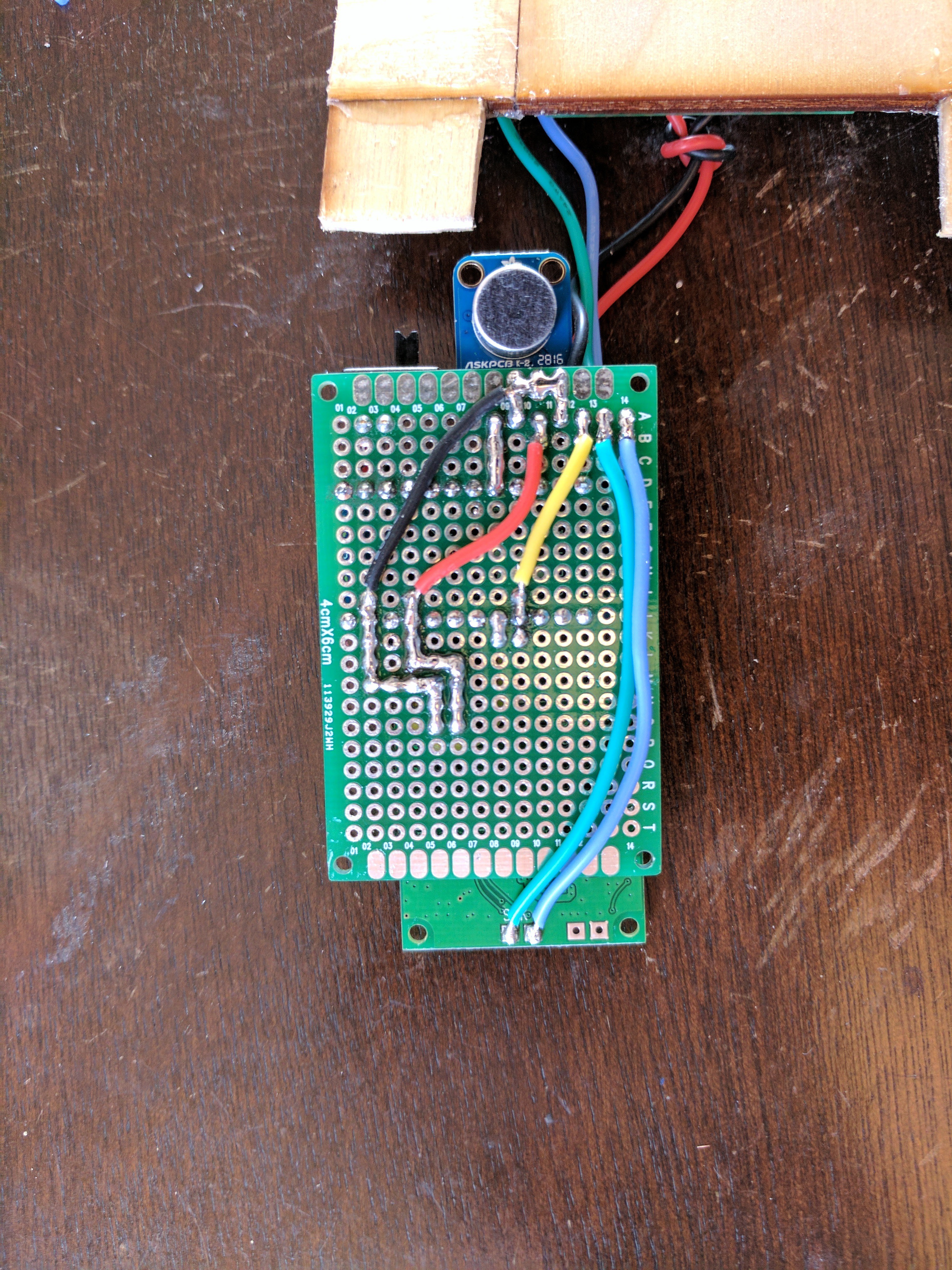
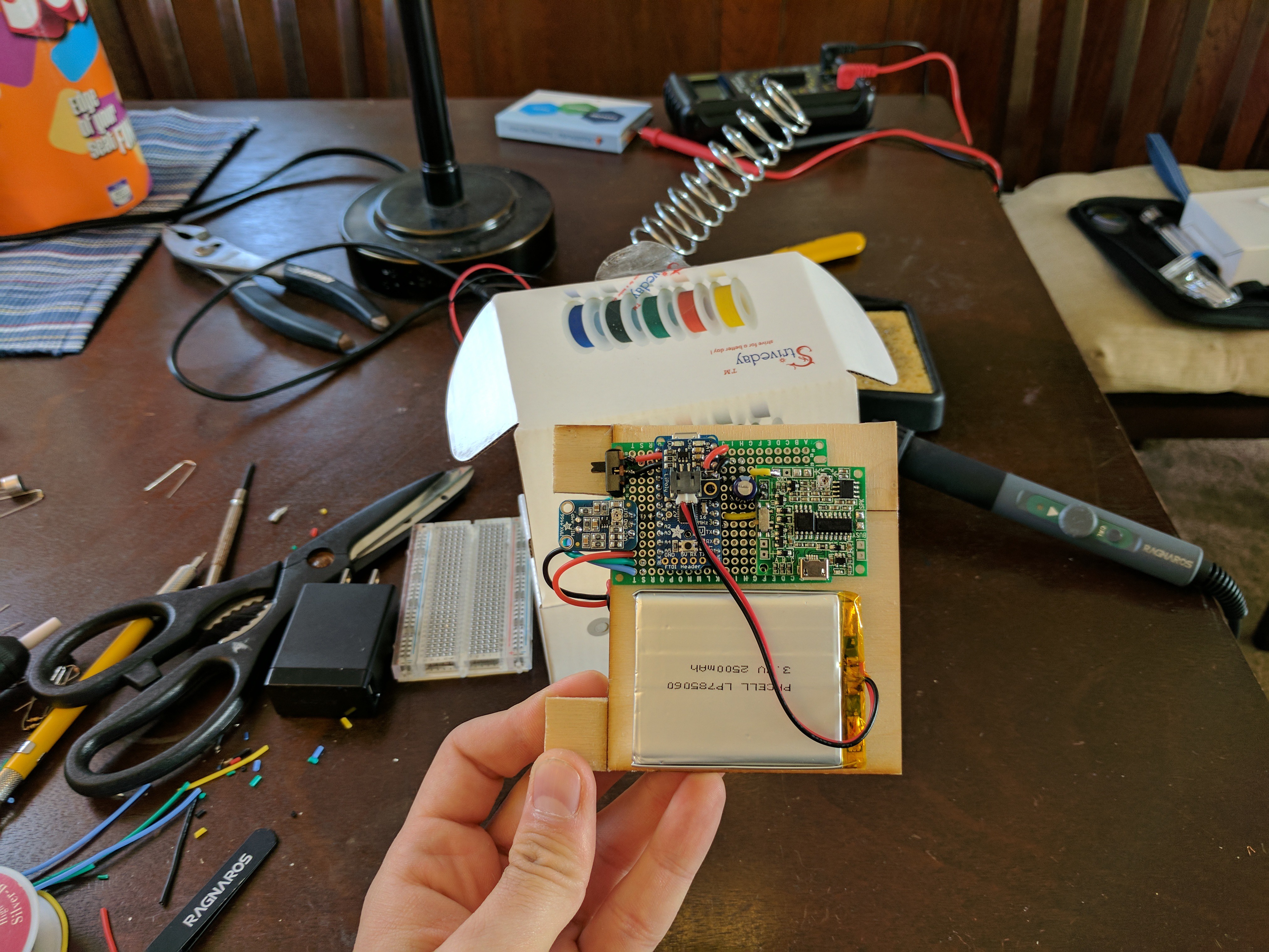
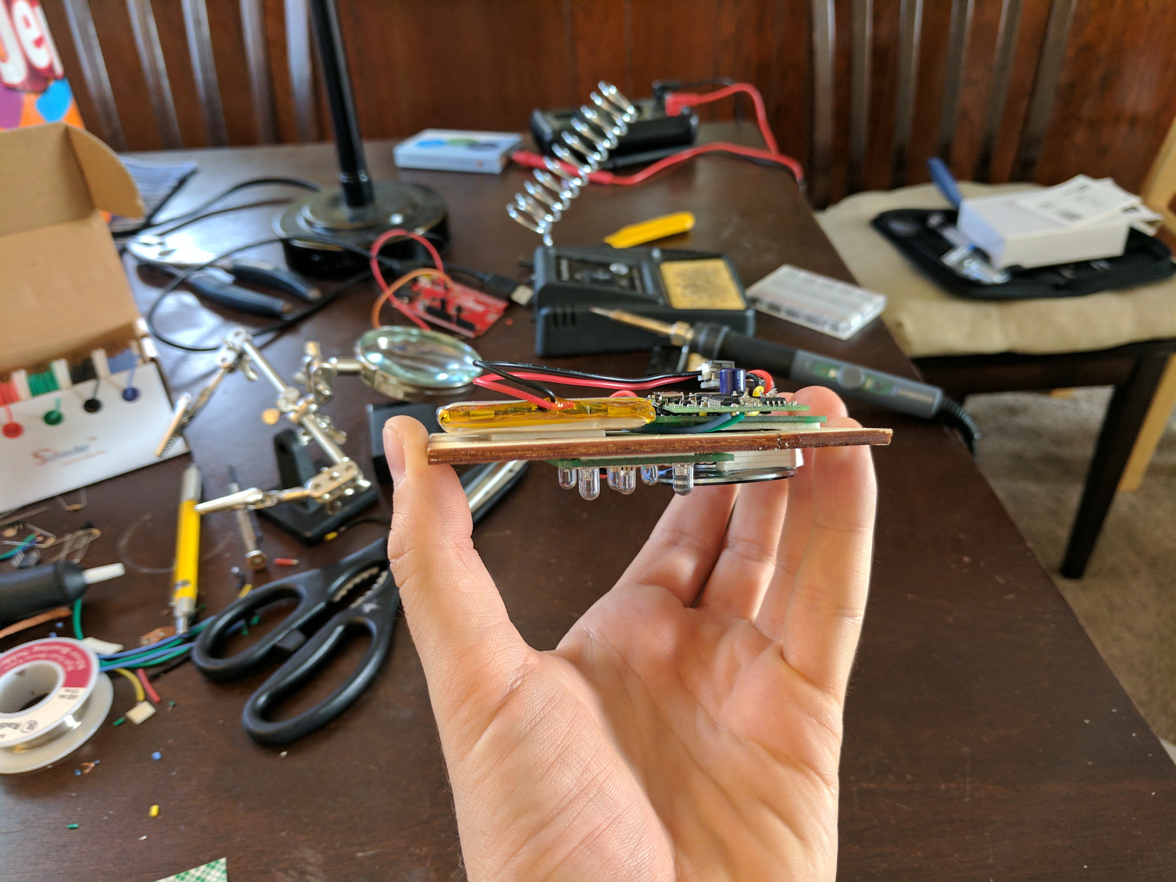
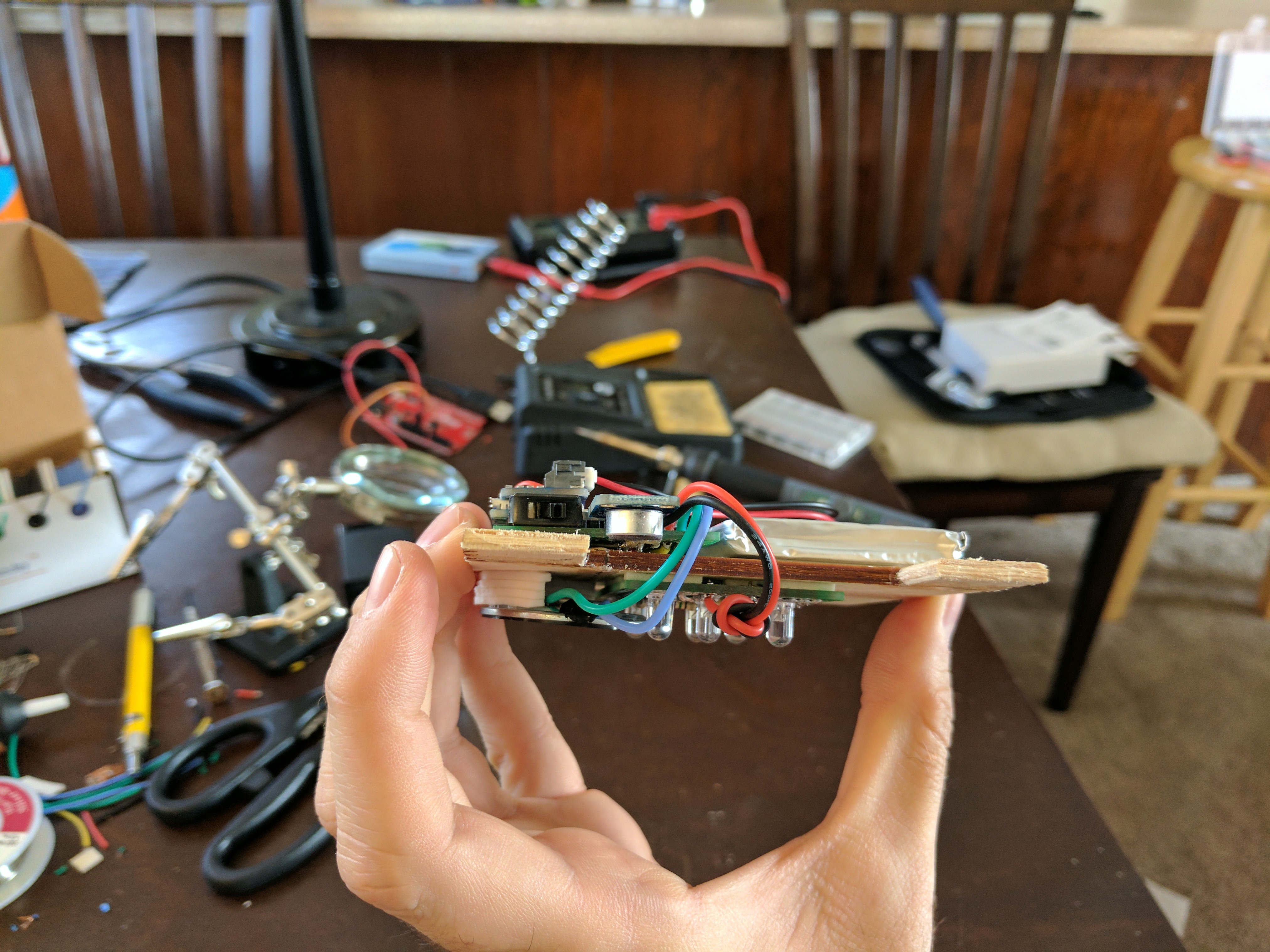
This is what the board and final mounted circuit look like:
Putting it all together
Now that everything was designed, built, redesigned, and rebuilt, it was time to put it all together and give it a go!
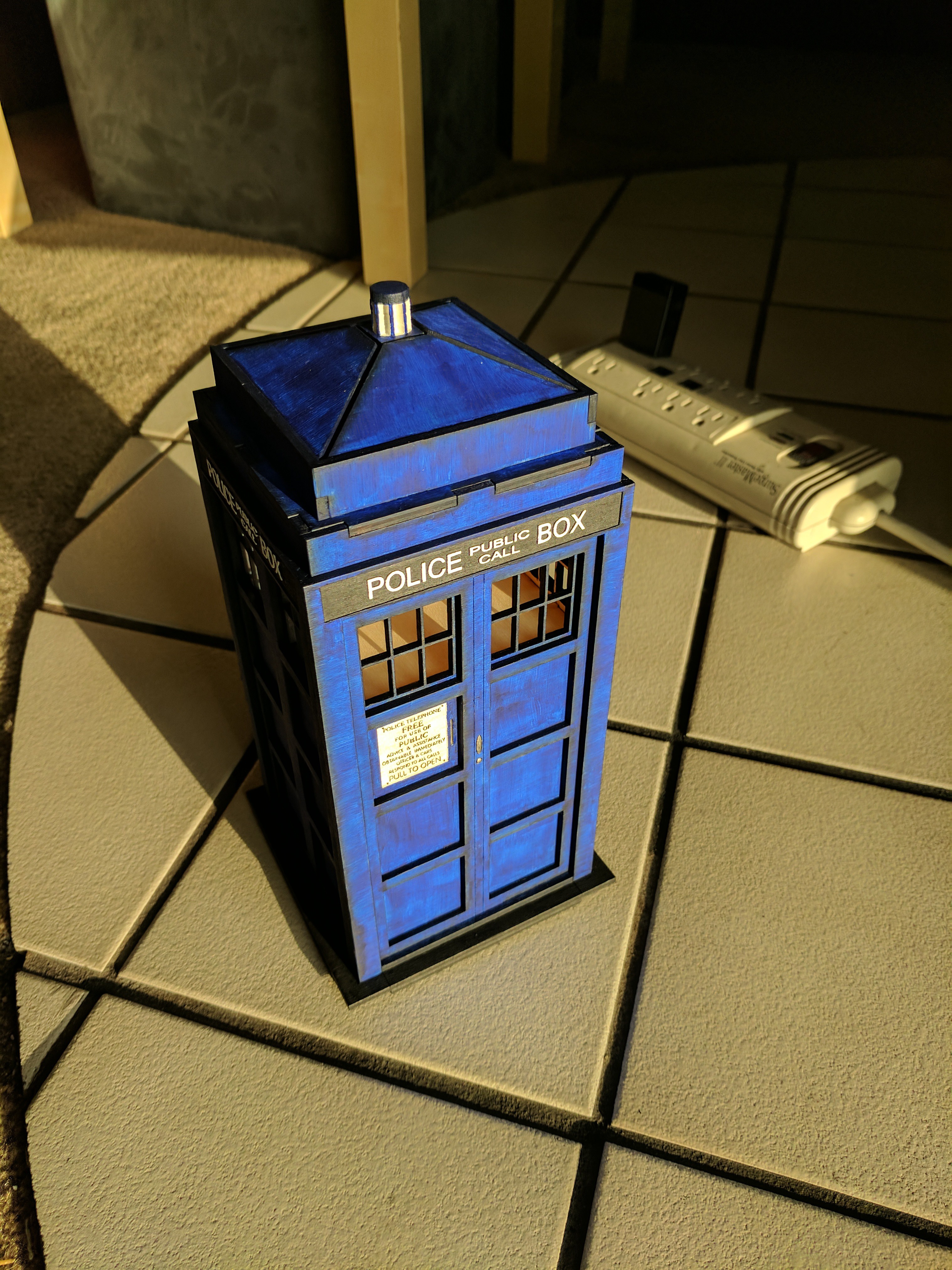
Here's how the the circuit looks when inserted into the TARDIS:
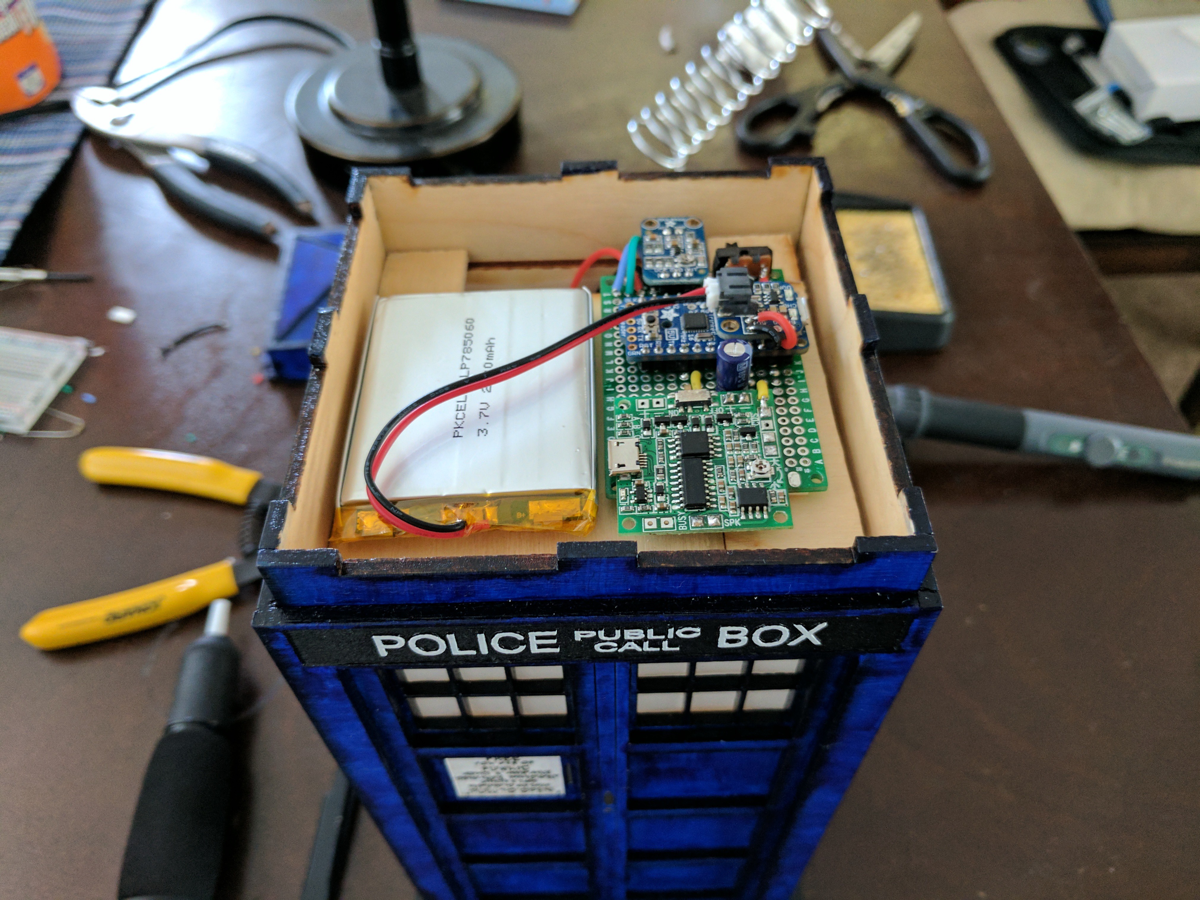
A nice, snug fit that can pop in and out easily.
And here's the video of the final TARDIS in action!
And with a little video magic, we get:
Addendum: Redesigning the light pulses
This section is also known as the "You're never really finished with a project, are you?" section...
I had everything working and integrated, but (as you might expect from me at this point) I became unhappy with the pulsing algorithm I had previously developed. It seemed to vary too smoothly and I didn't think it really captured the strong, periodic pulses of the audio well enough.
I redesigned the algorithm to use shorter pulses with pauses in between to synchronize with the loudest part of the audio
This is what the final pusling pattern looks like:
And here is a video of it in action:
Again, you can find the Arduino sketch for this at https://github.com/sifounak/TARDIS_Box_Project.
I'm pretty sure no one will notice such a small difference, but it's one of those "I did this for me" kind of things.
I guess you could say that "I did this for me" philosophy applies to this whole project, so maybe that doesn't really say much... *shrug*
Final thoughts
I spent SIGNIFICANTLY more time and money on this project than I had originally expected to, but, honestly...
Is it the greatest thing ever built?
NOPE!
Is it the greatest thing I've ever built?
NOPE!
Did it require a combination of skills that I think no one else has?
NOPE!
But was it totally worth it because it makes me smile whenever I look at it, friends/family/co-workers find it pretty neat, and it's even bigger* on the inside?
YUP!
* Well, there's more to it on the inside than you would expect. Let's let that detail slide for now...
My advice to others that love tinkering and are thinking of making something:
Just make something.
Don't wait to make the most amazing thing anyone has ever seen or something that's never been done before.
Make something that makes you happy because, no matter what it is, it will be yours and you'll learn a hell of a lot doing it!
As small and silly as this project might be, I took the time to make this write up so that it might inspire others to make something like this, so that others could more easily replicate what I did without as many mistakes, and so that I could one day look back on this project and remember how damn excited I was when I made this little thing!
I'm hoping it'll be one of those rare moments where Past Self did something nice for Future Self.
Way to go, Past Self!