0%
0%
Concrete CNC
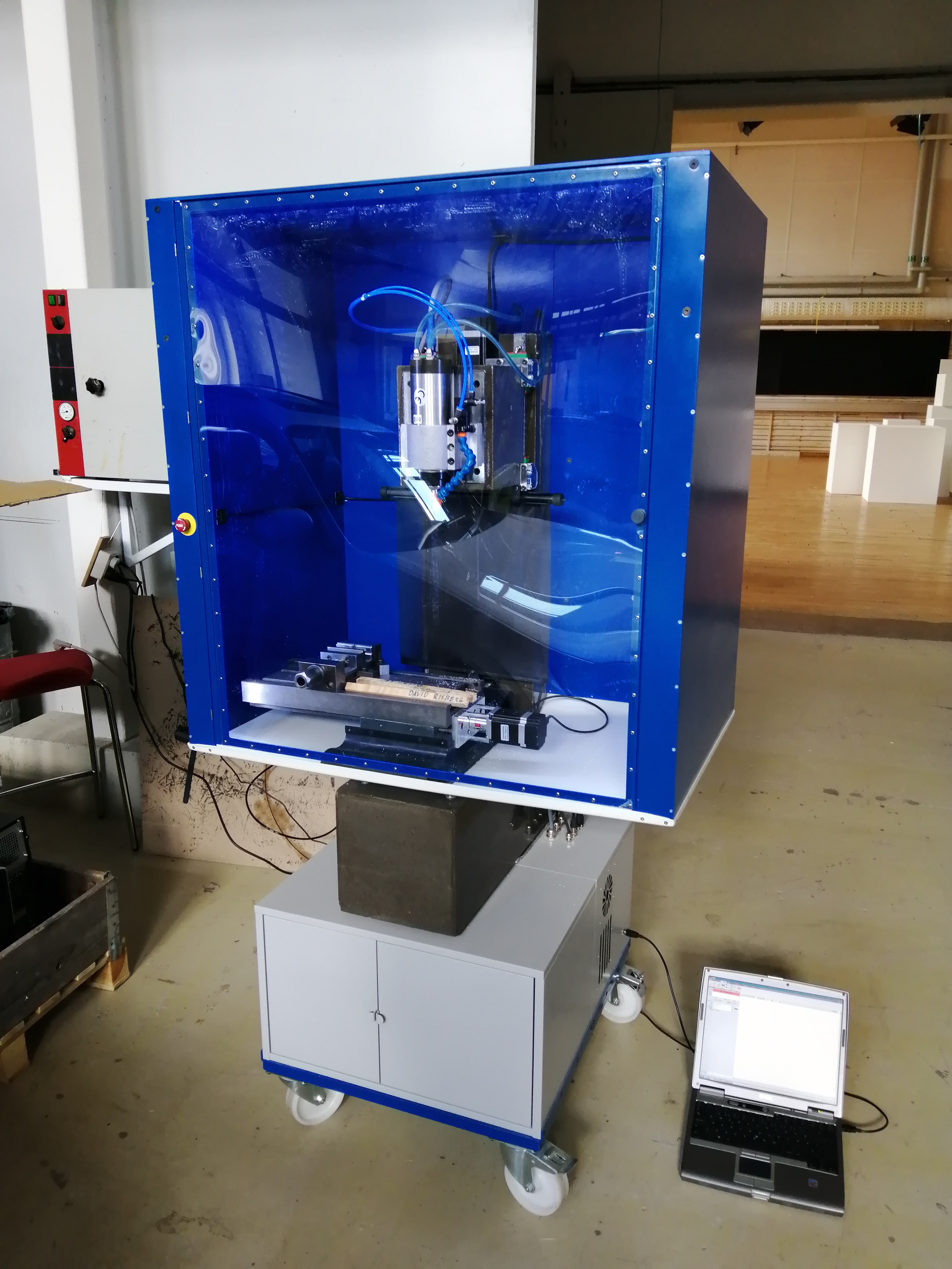
This is an attempt at a cheap but rigid CNC machine (budget approx. 2000€)
Become a Hackaday.io member
Already have an account? Log in.
Just one more thing
To make the experience fit your profile, pick a username and tell us what interests you.
Pick an awesome username
hackaday.io/
Your profile's URL: hackaday.io/username. Max 25 alphanumeric characters.
Pick a few interests
Projects that share your interests
People that share your interests
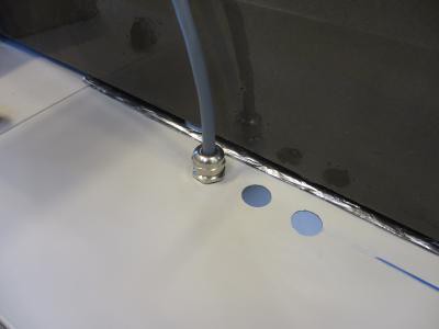
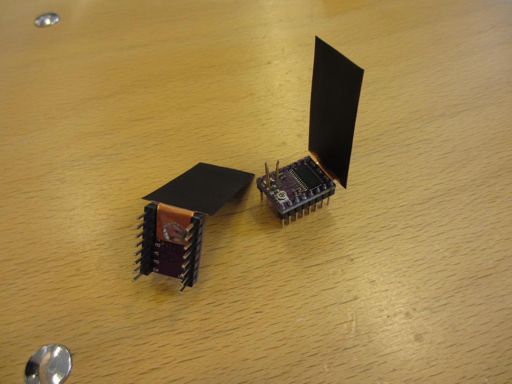
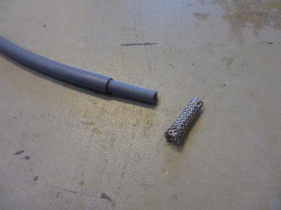 Put this on you other cable and peel a short section just inside the cable gland.
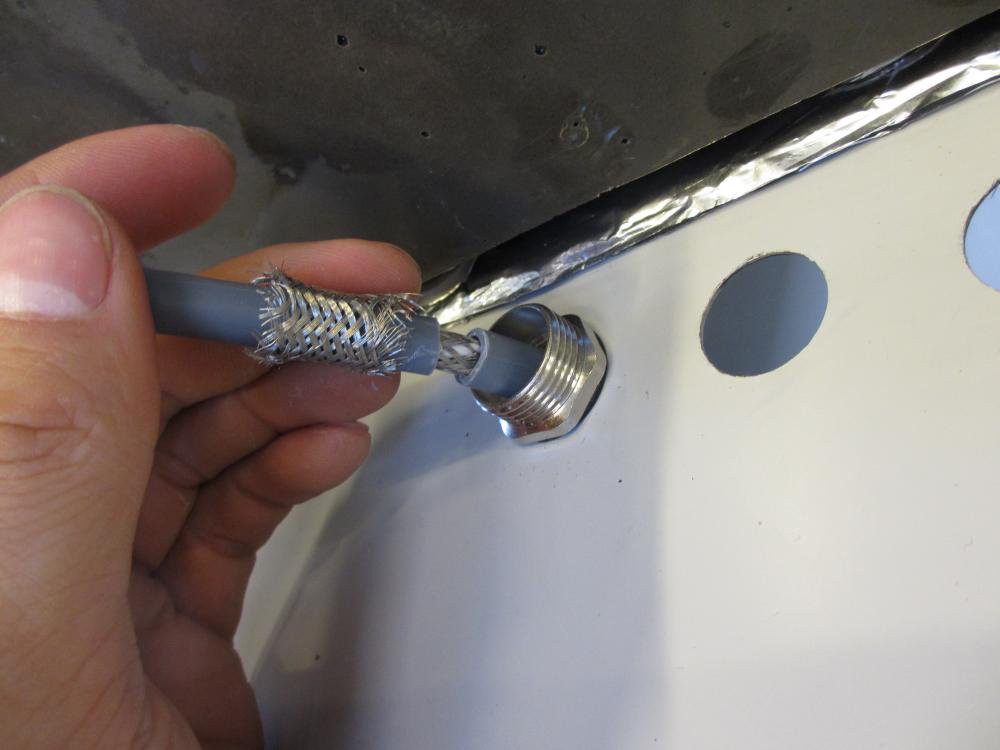
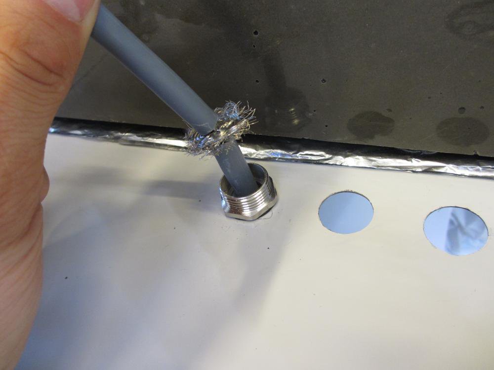
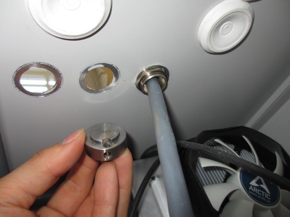

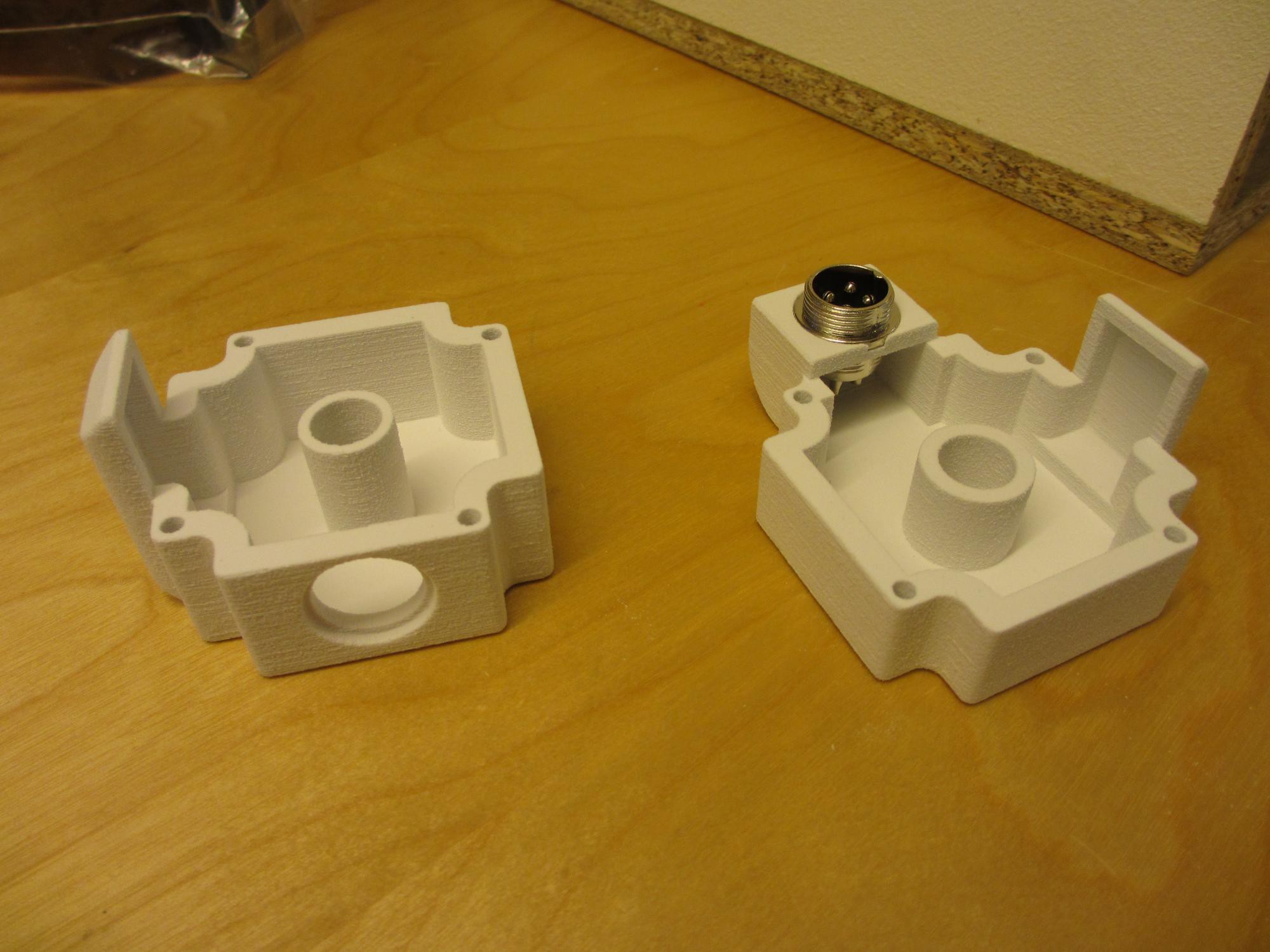
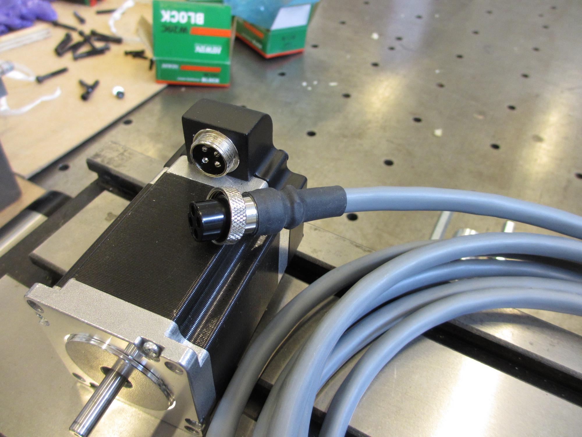
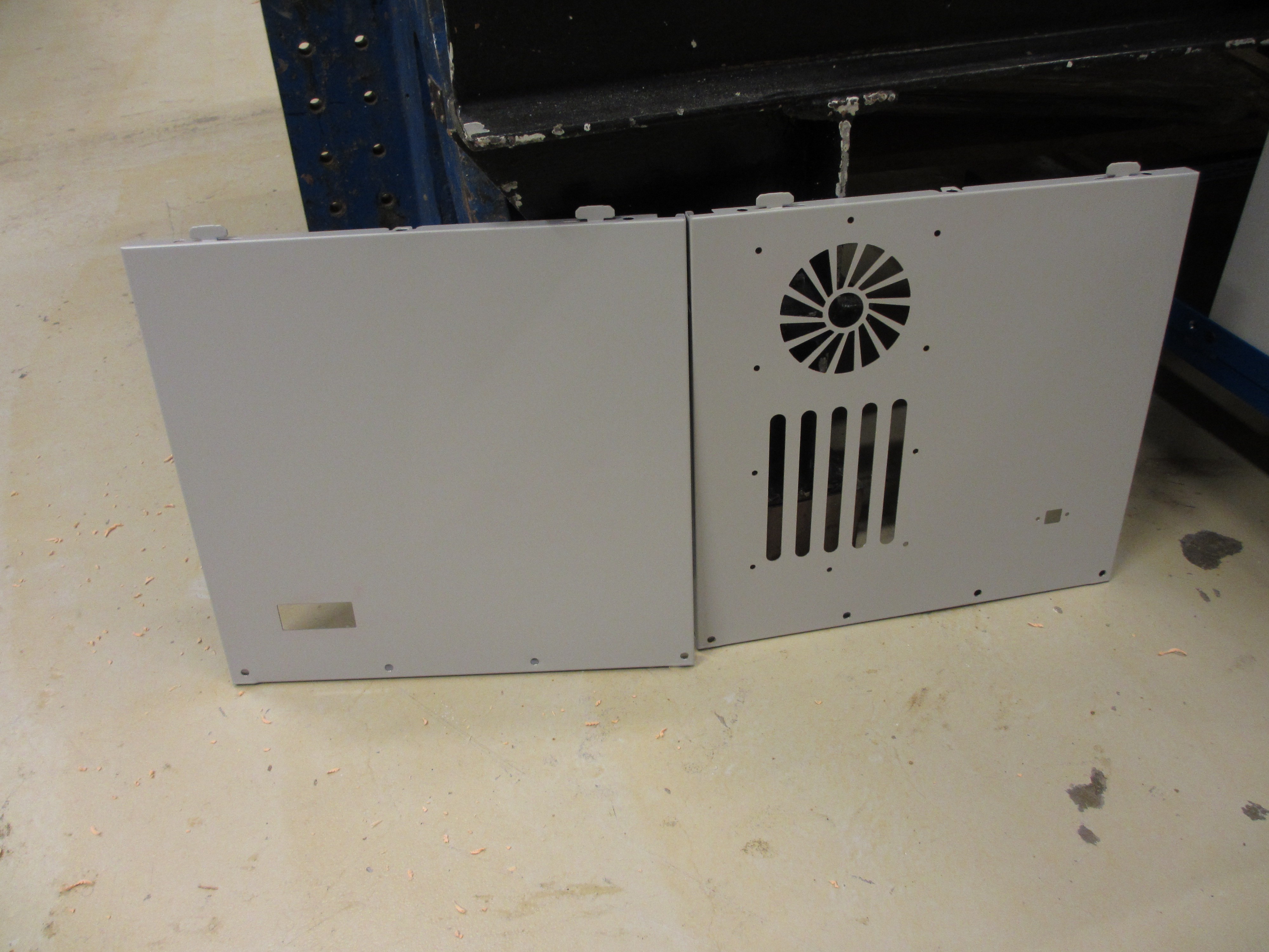
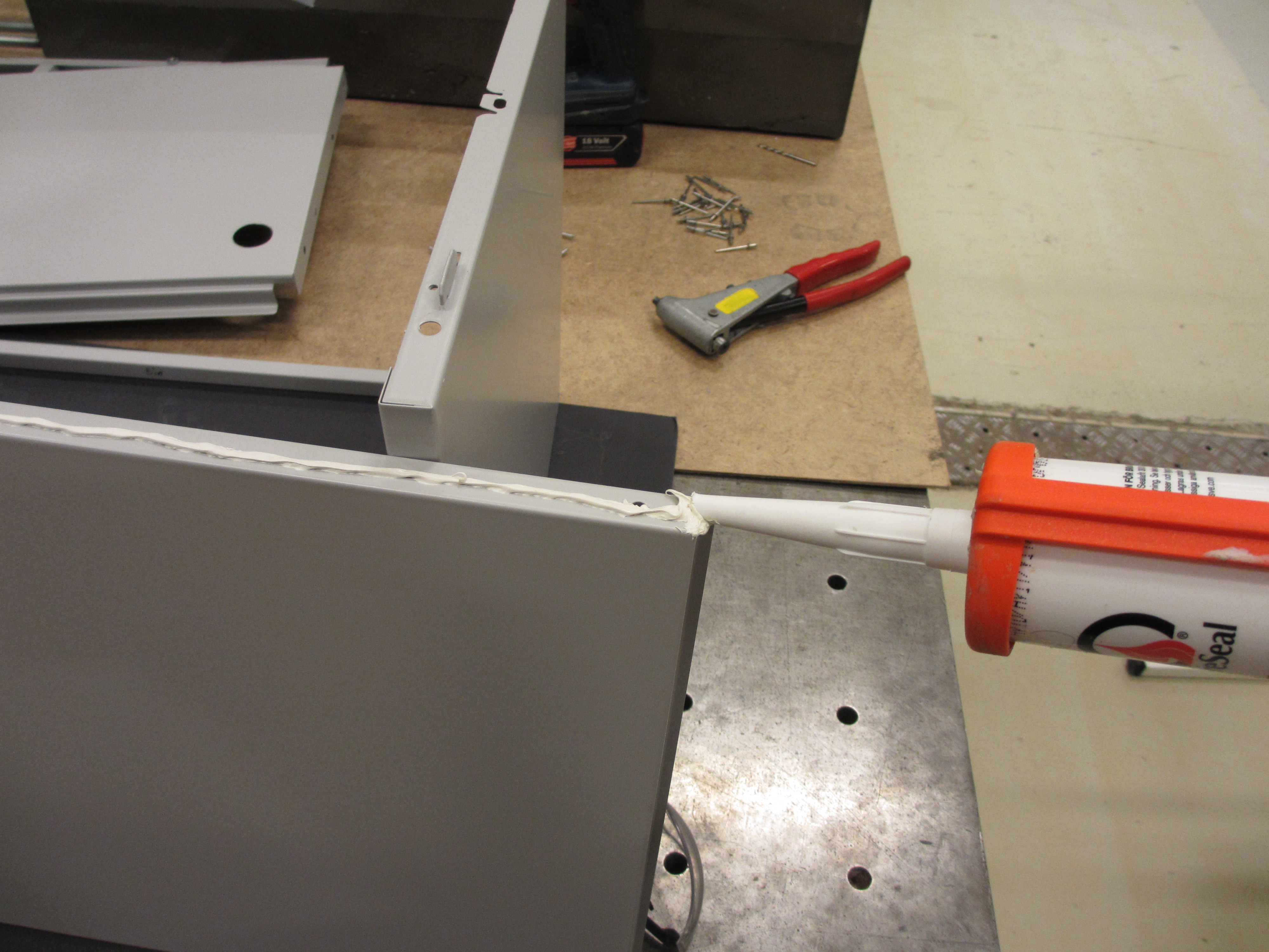
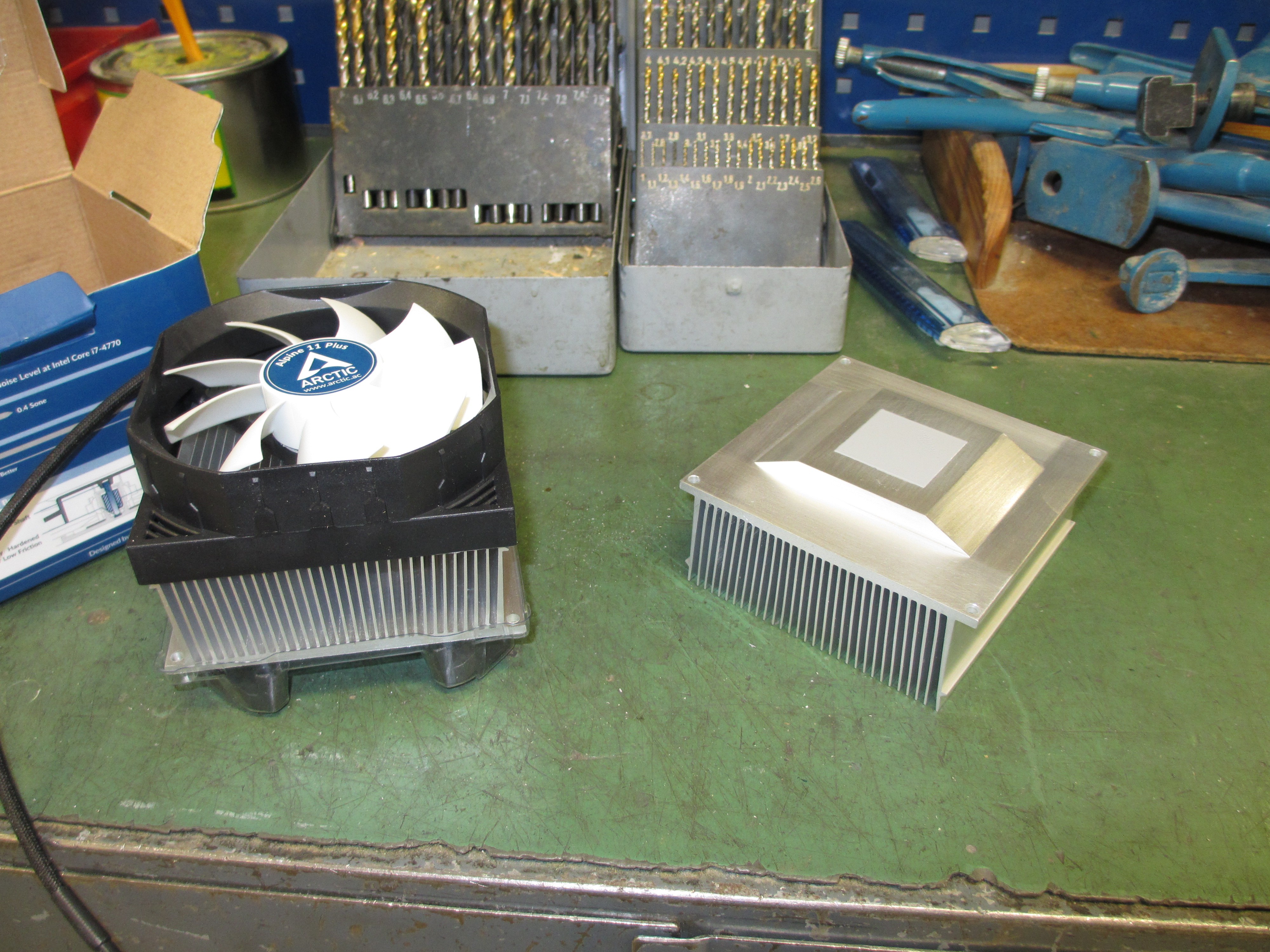
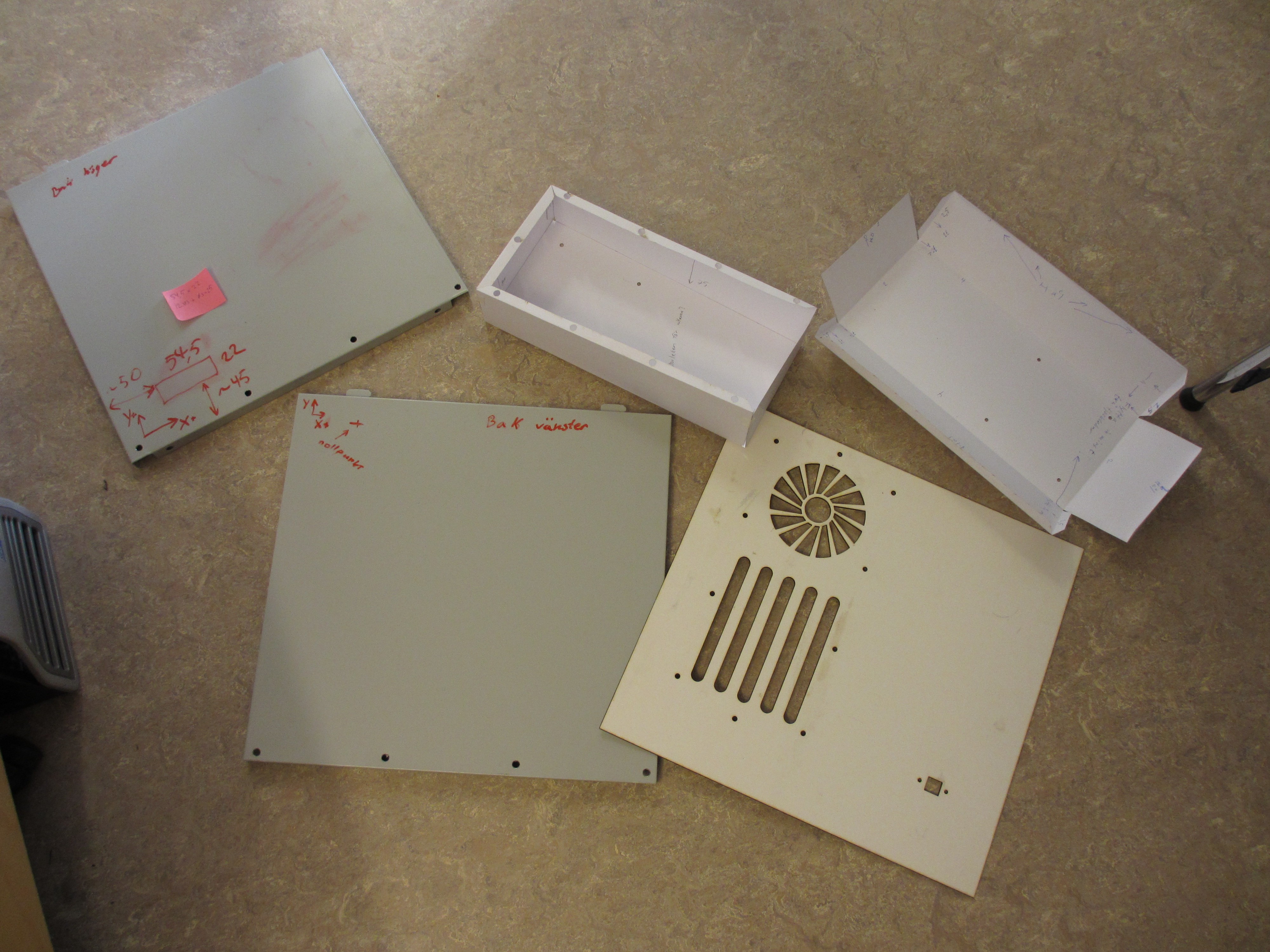
 Next up is mounting the heatsinks to the aluminium box that I made (designed in Freecad and cut from 0,7mm aluminium in the water cutter at Sliperiet fab lab. Then folded together in our workshop). I started by rubbing all surfaces with fine steel wool and alcohol to smooth them out and remove oxides. Then cleaned it with paper and finally a lint-free rag.
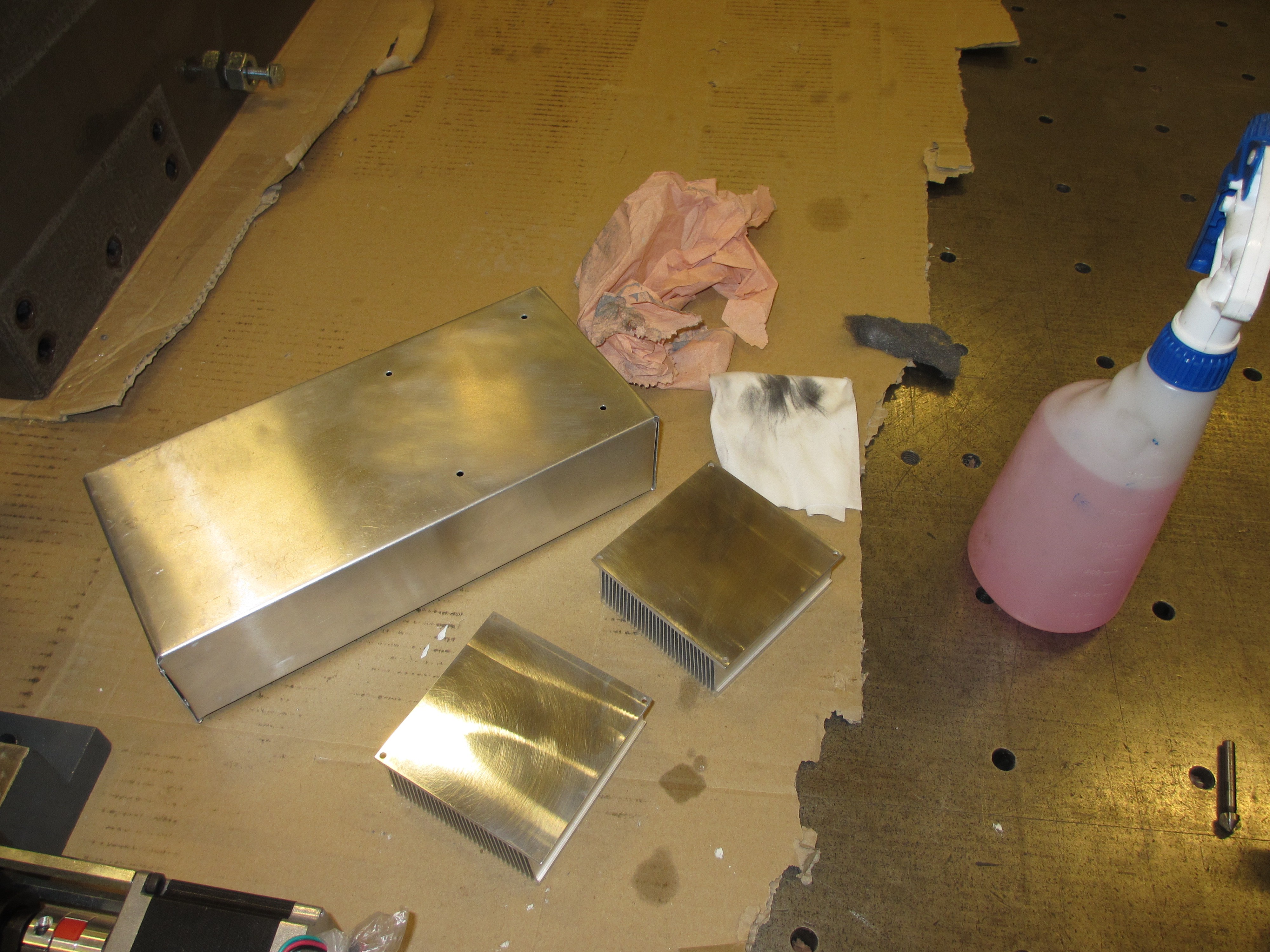
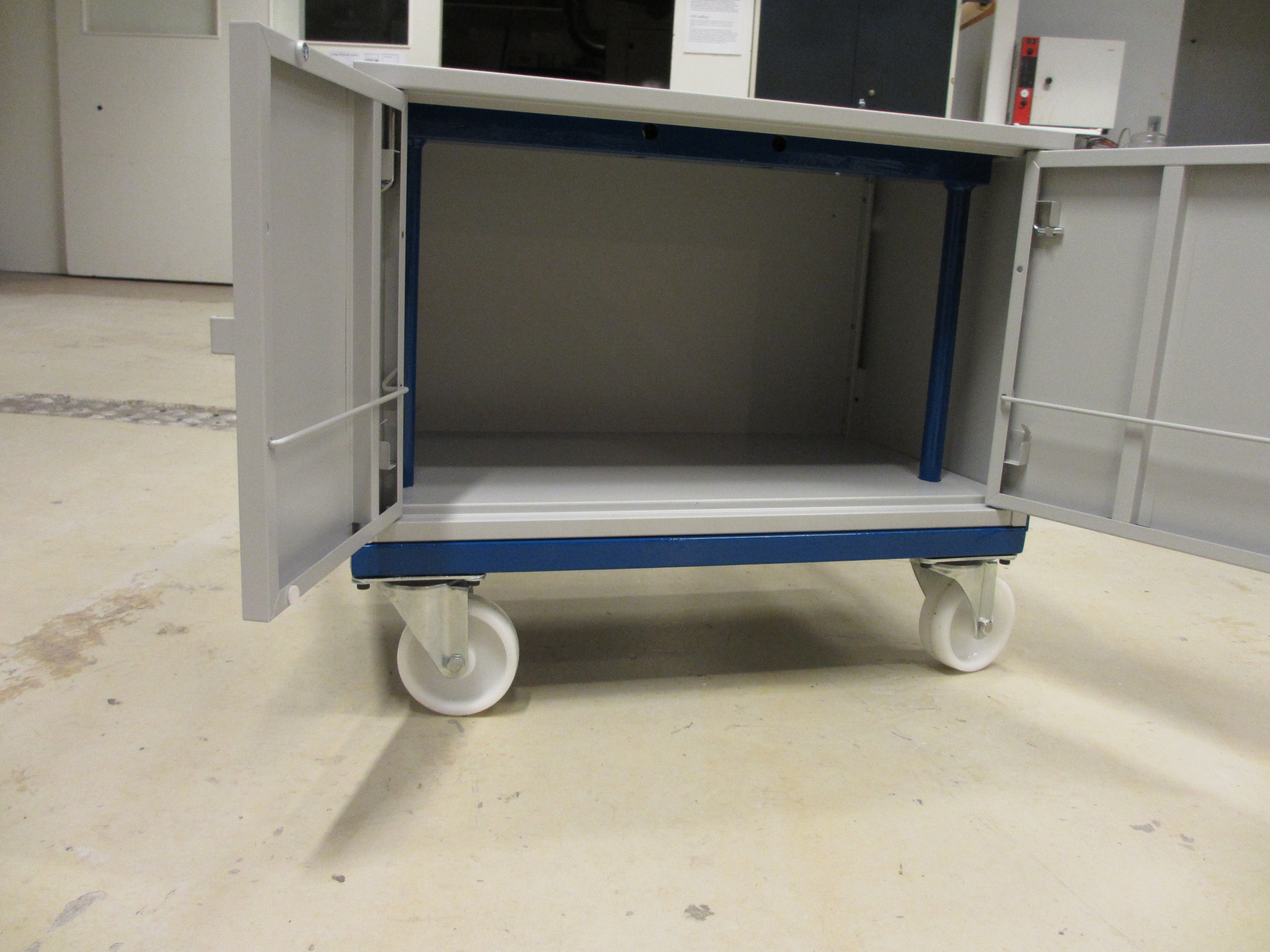
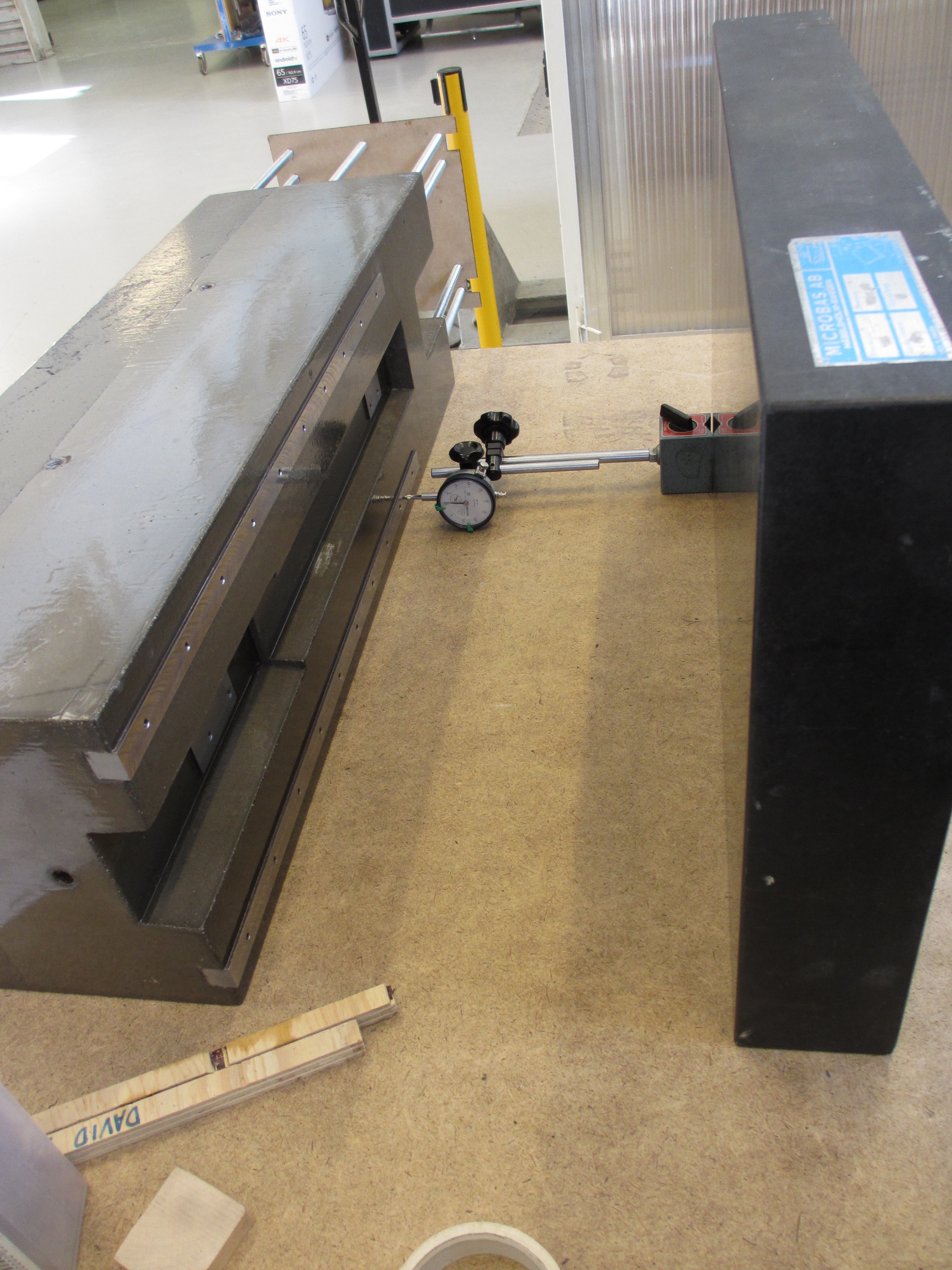
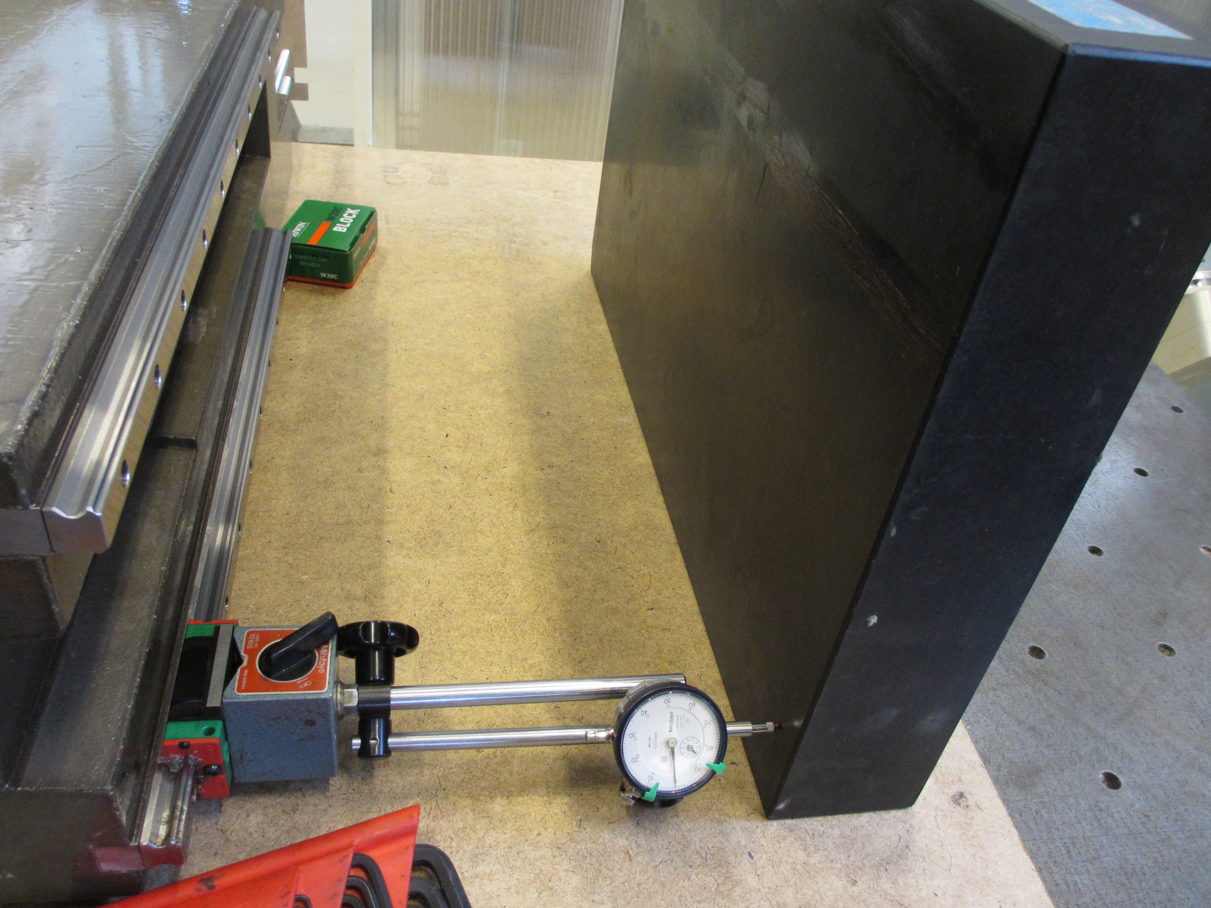
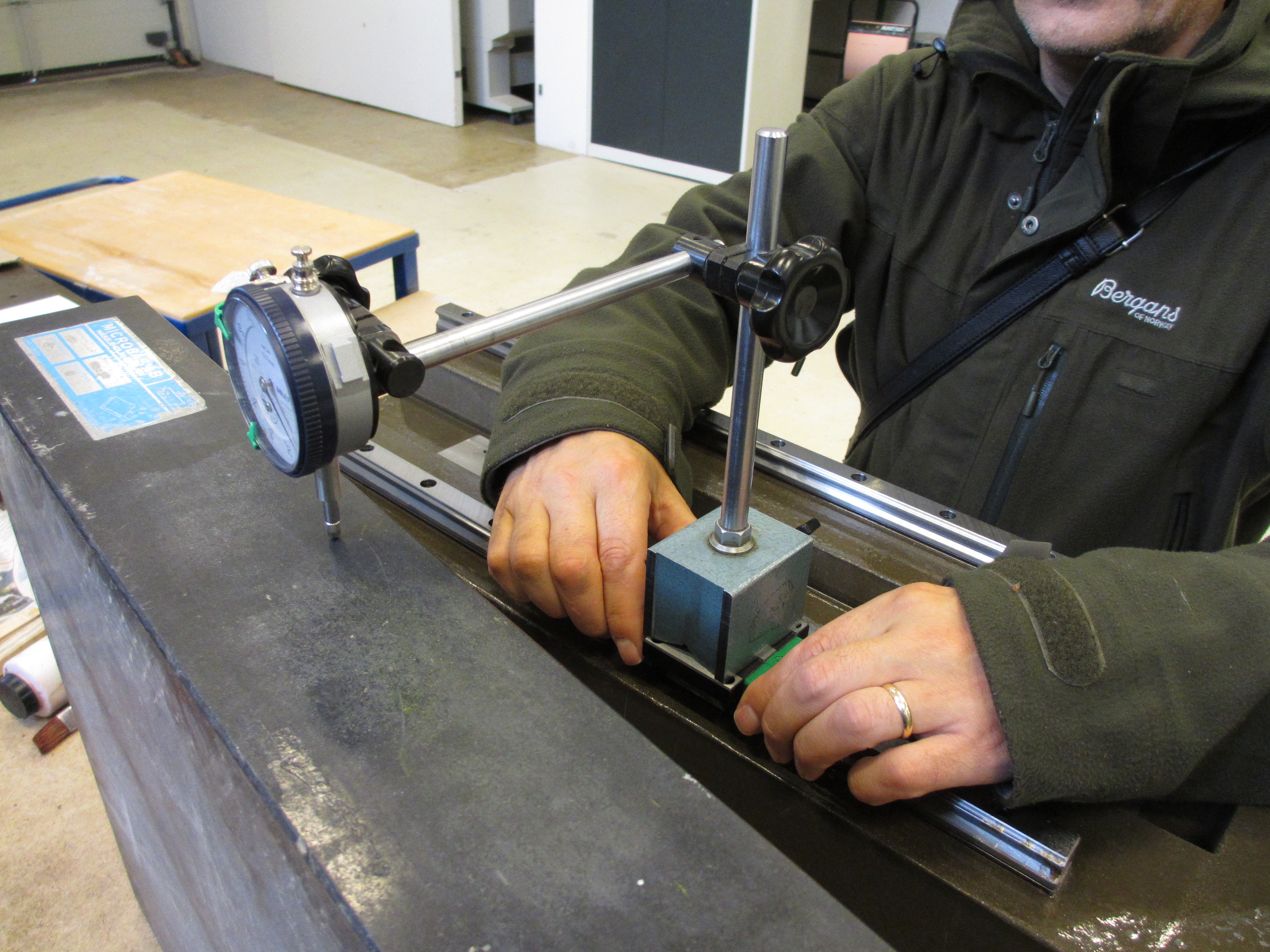
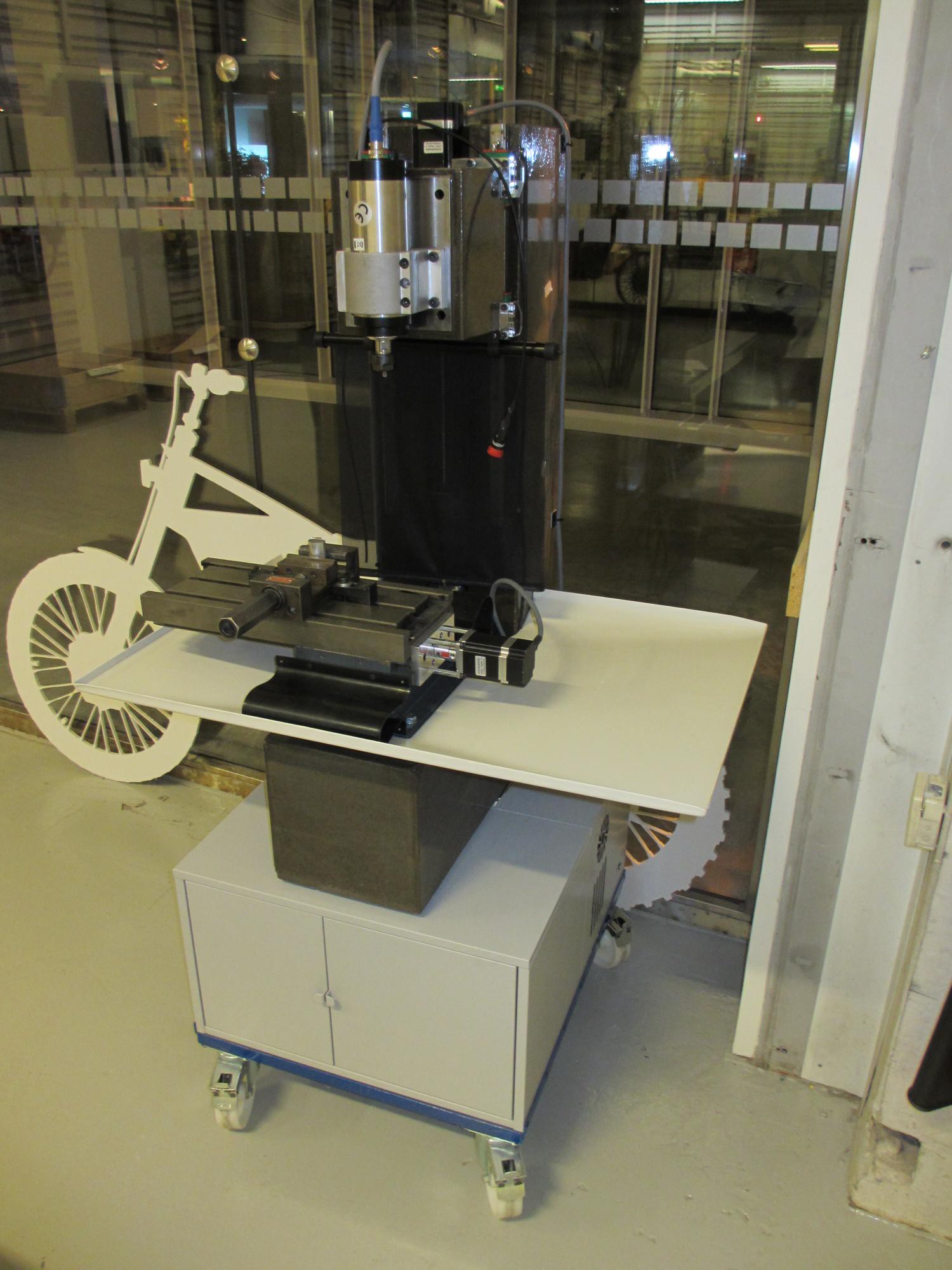
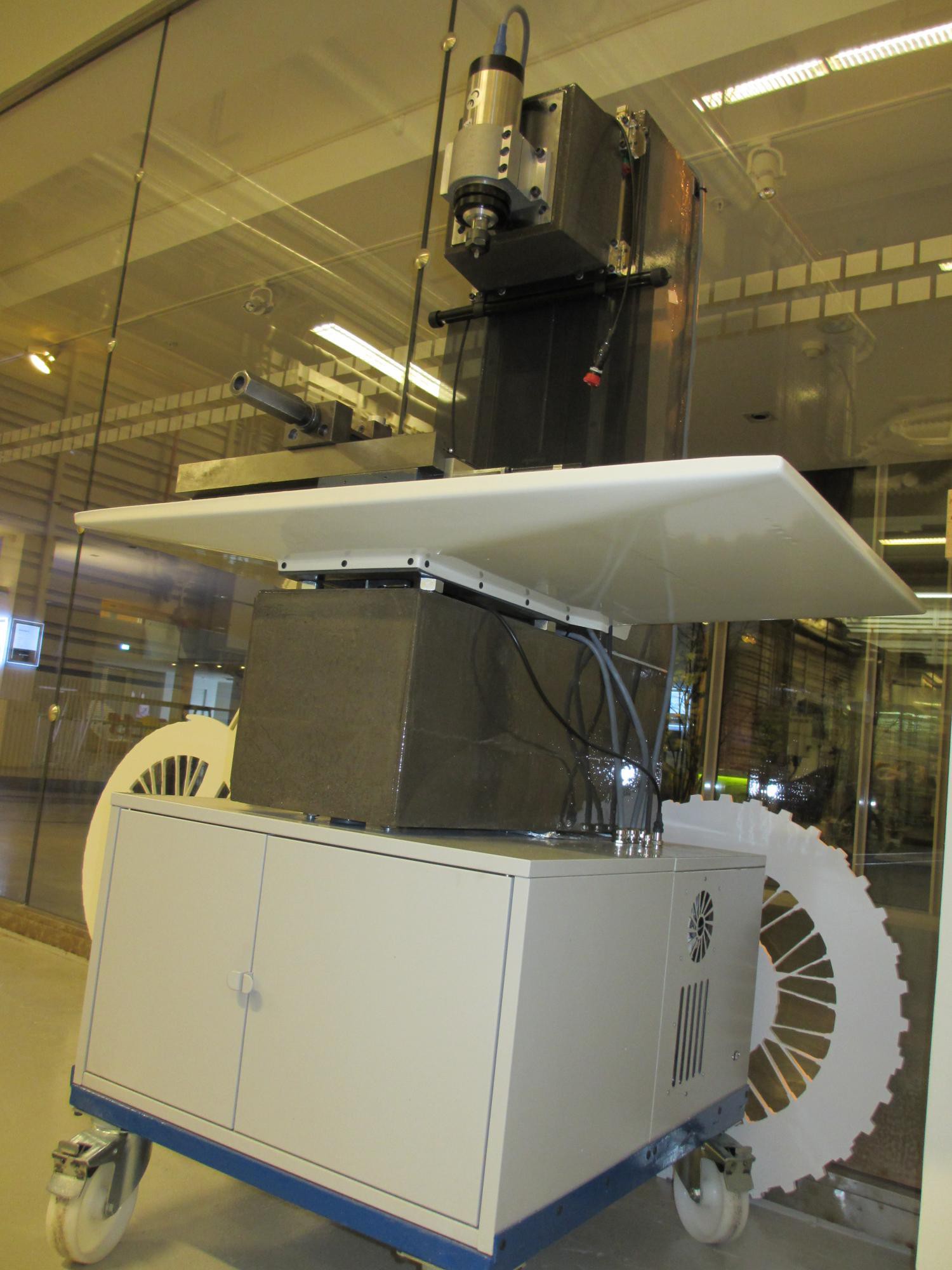
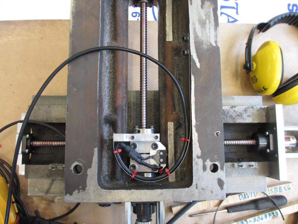
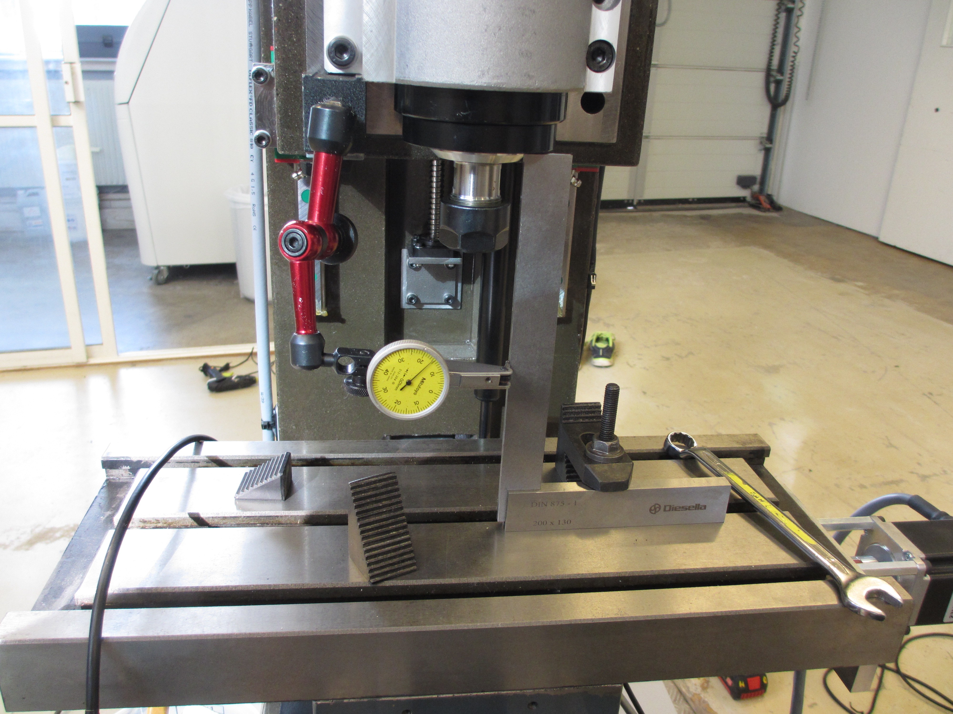
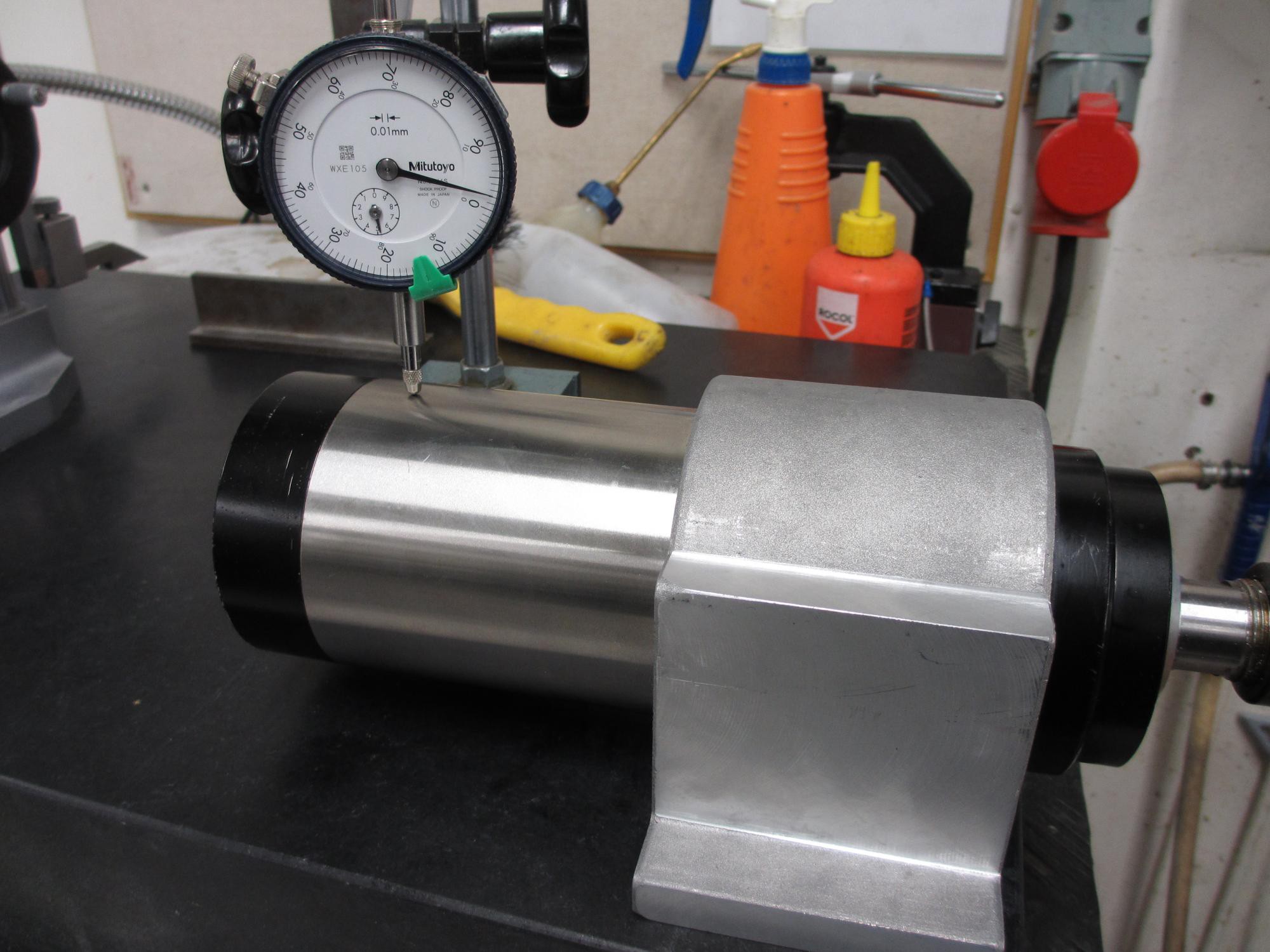
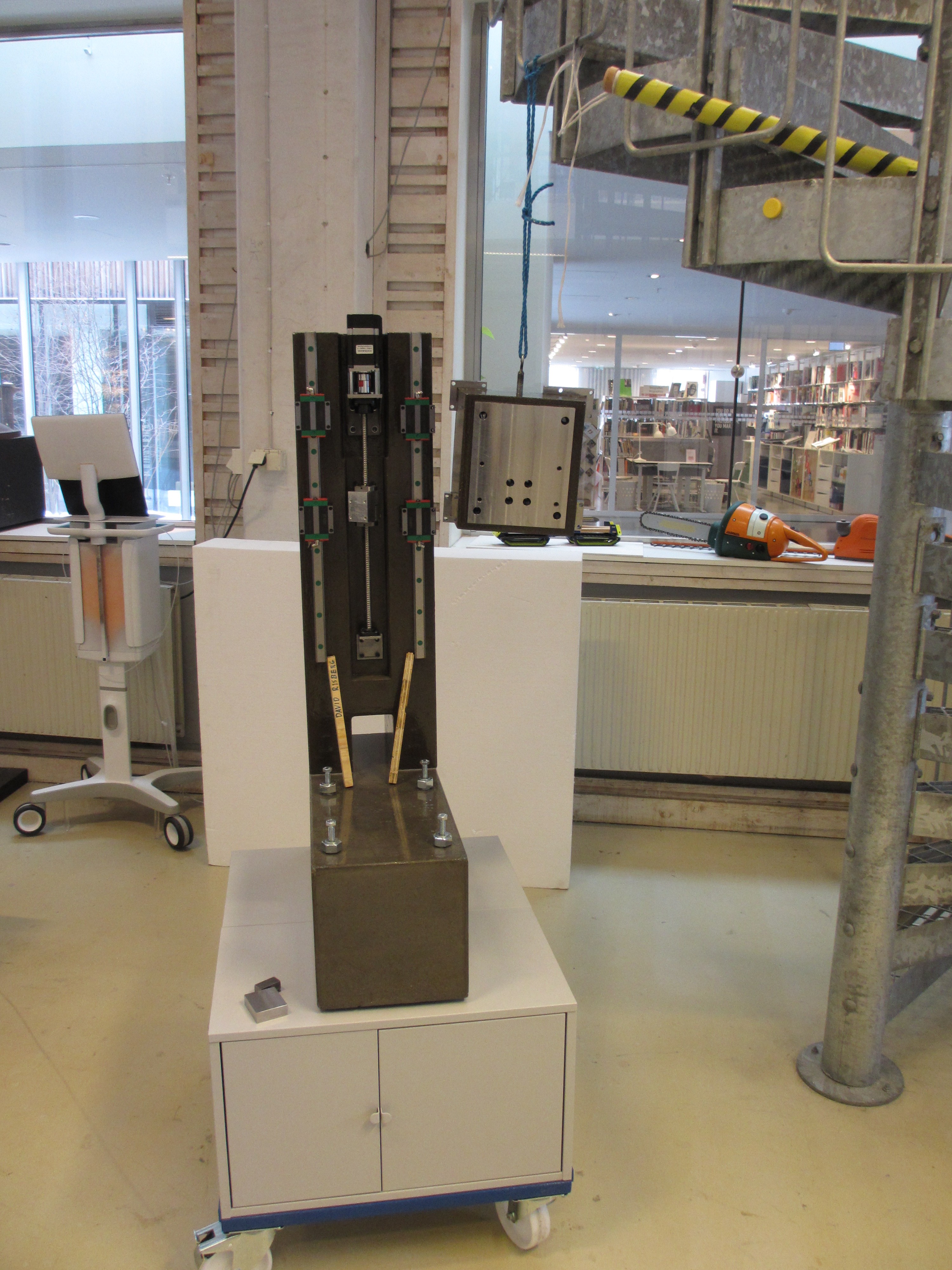
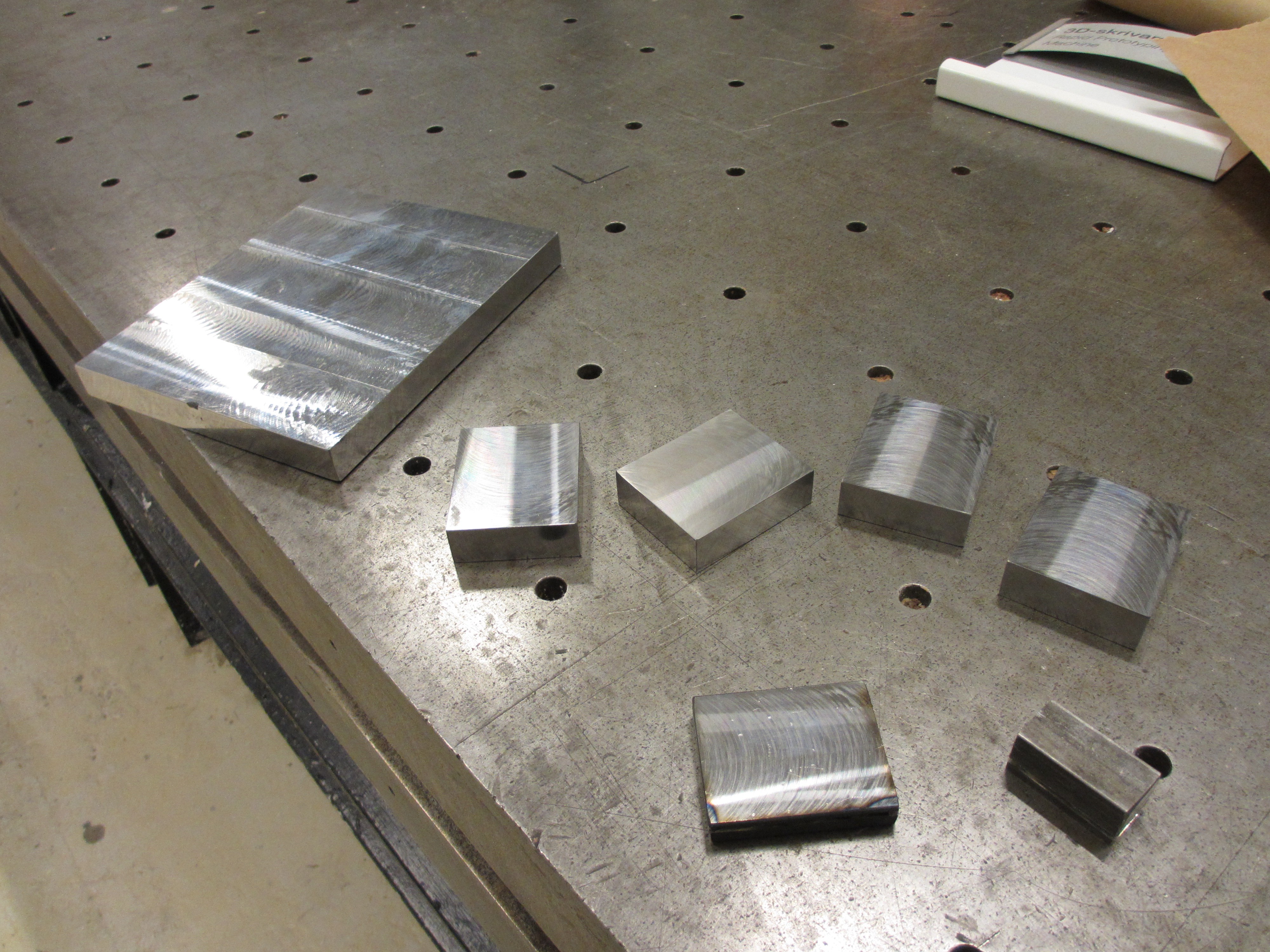
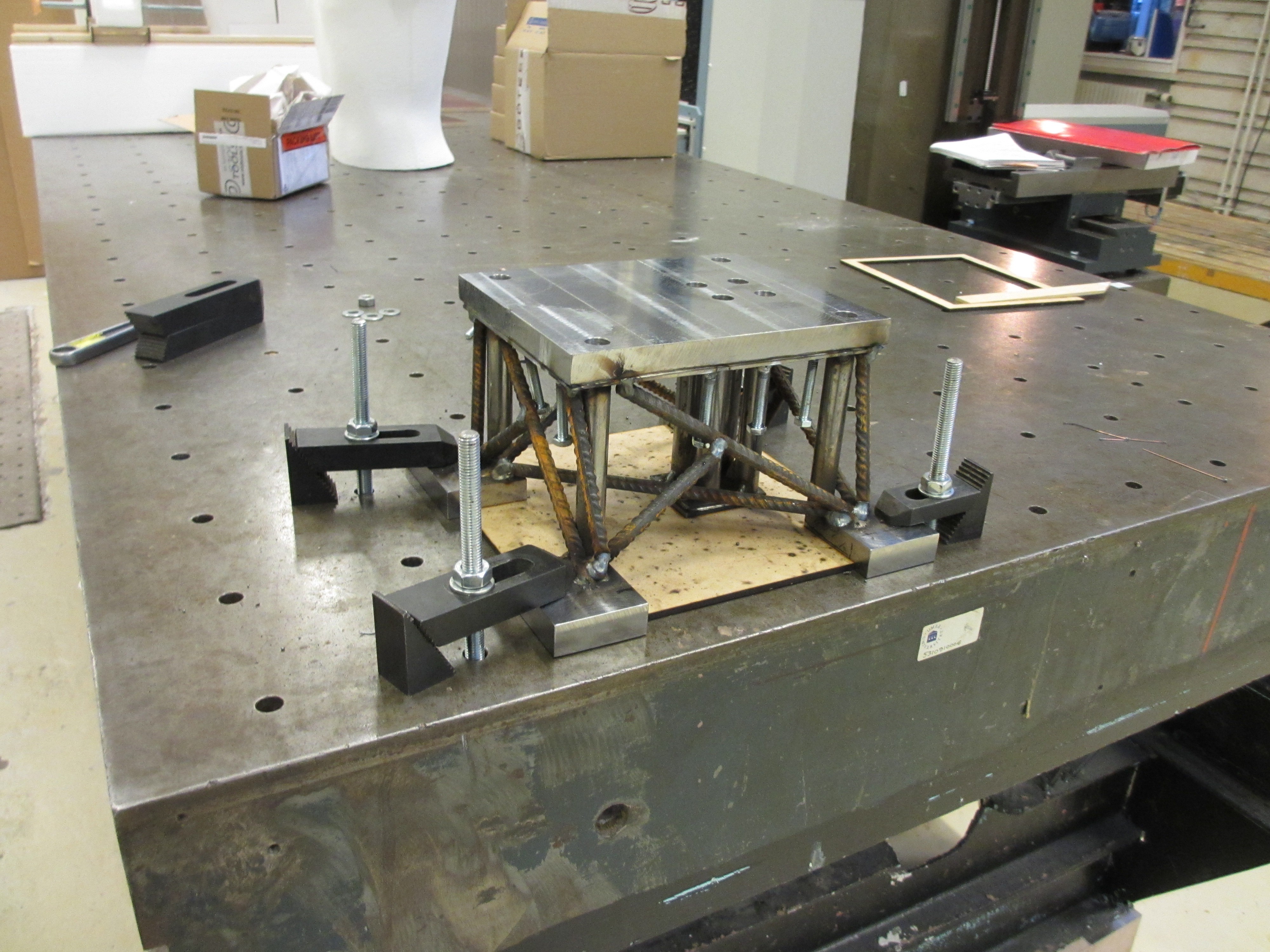
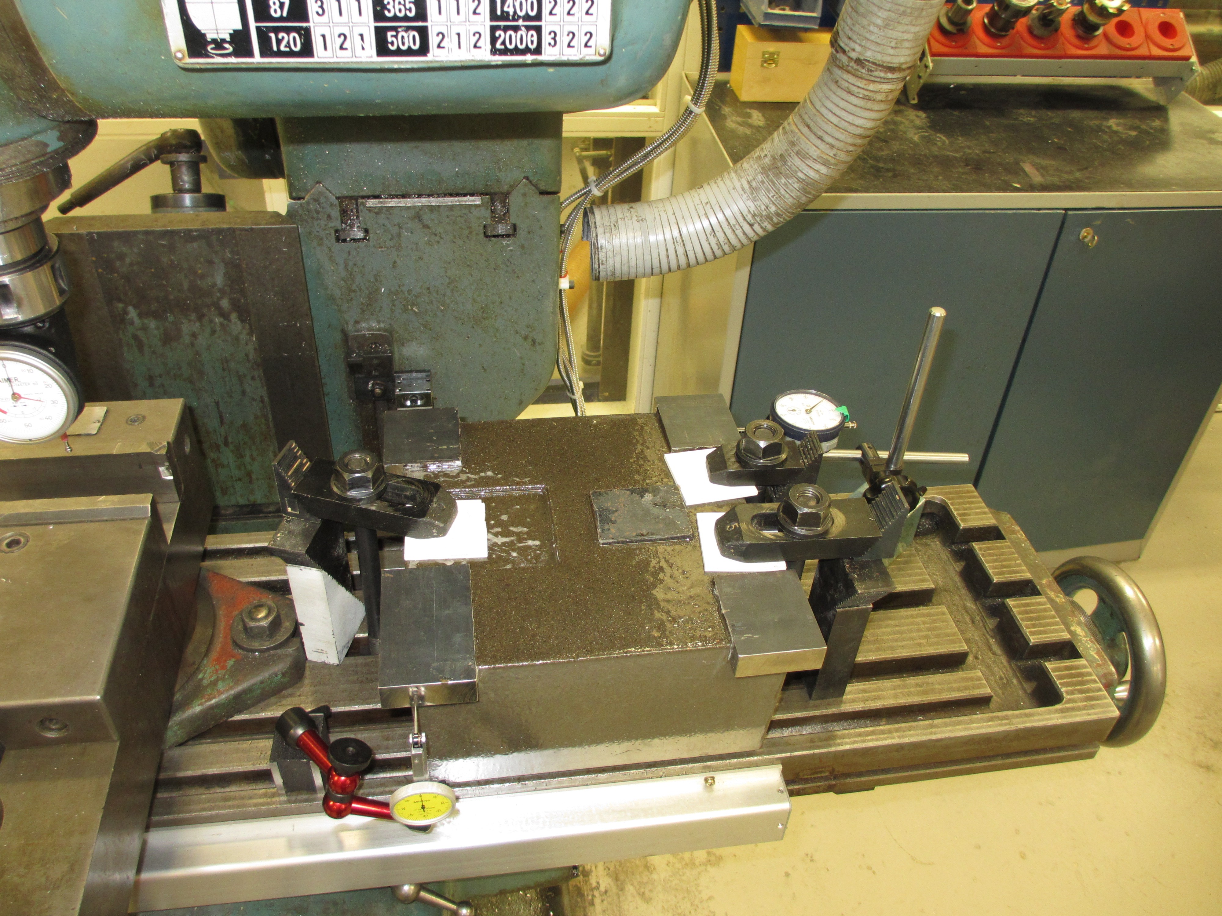
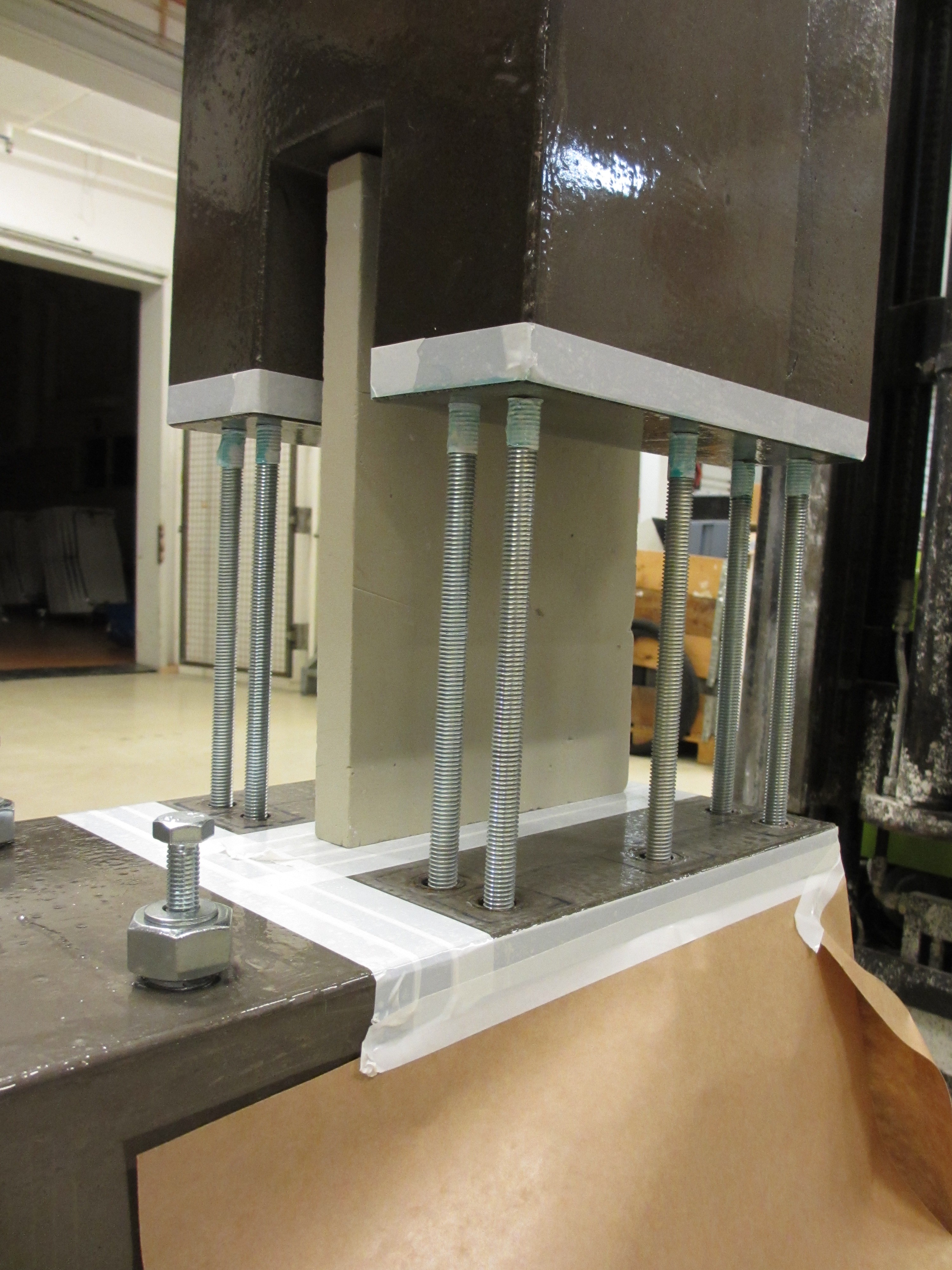
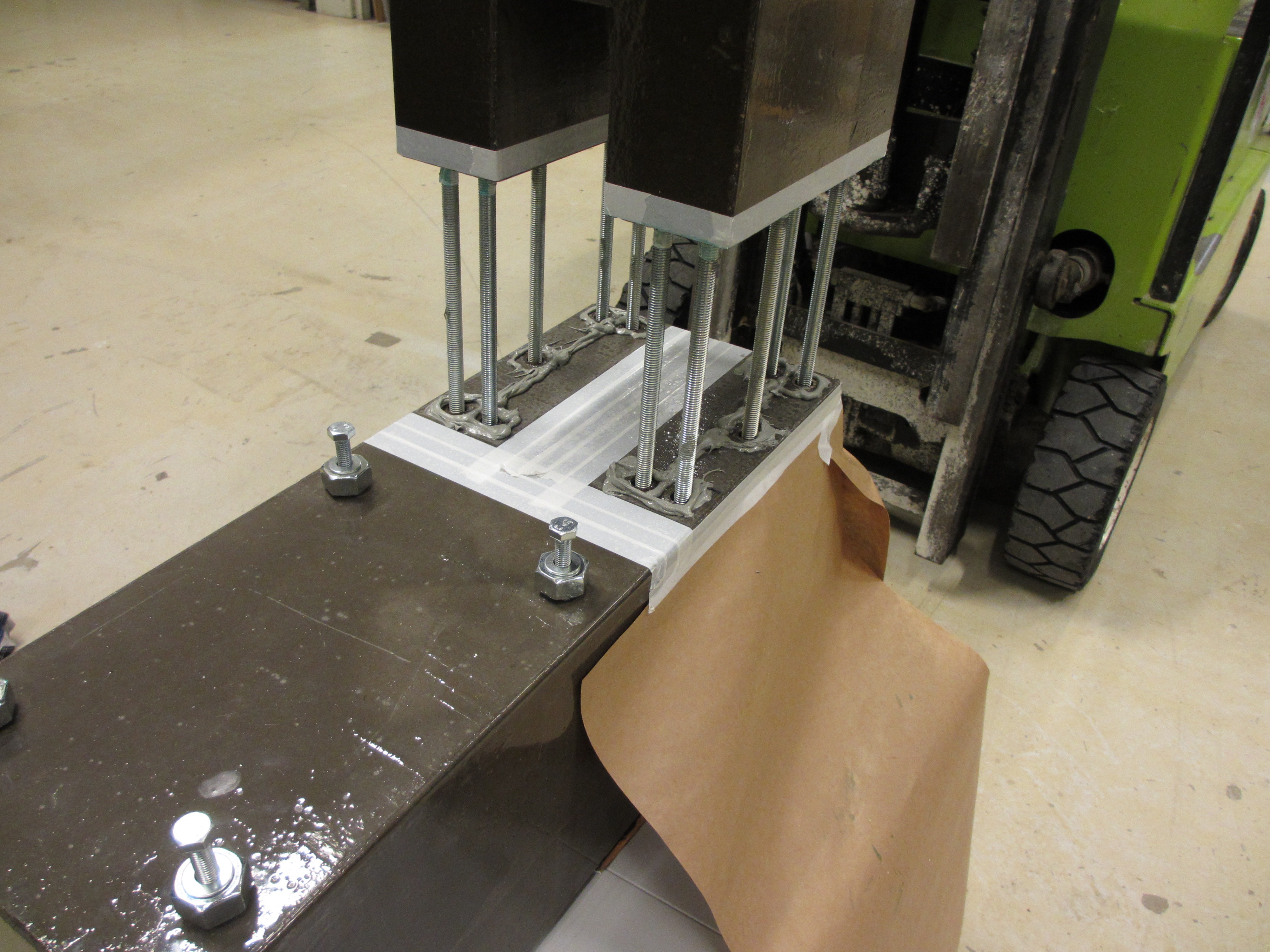
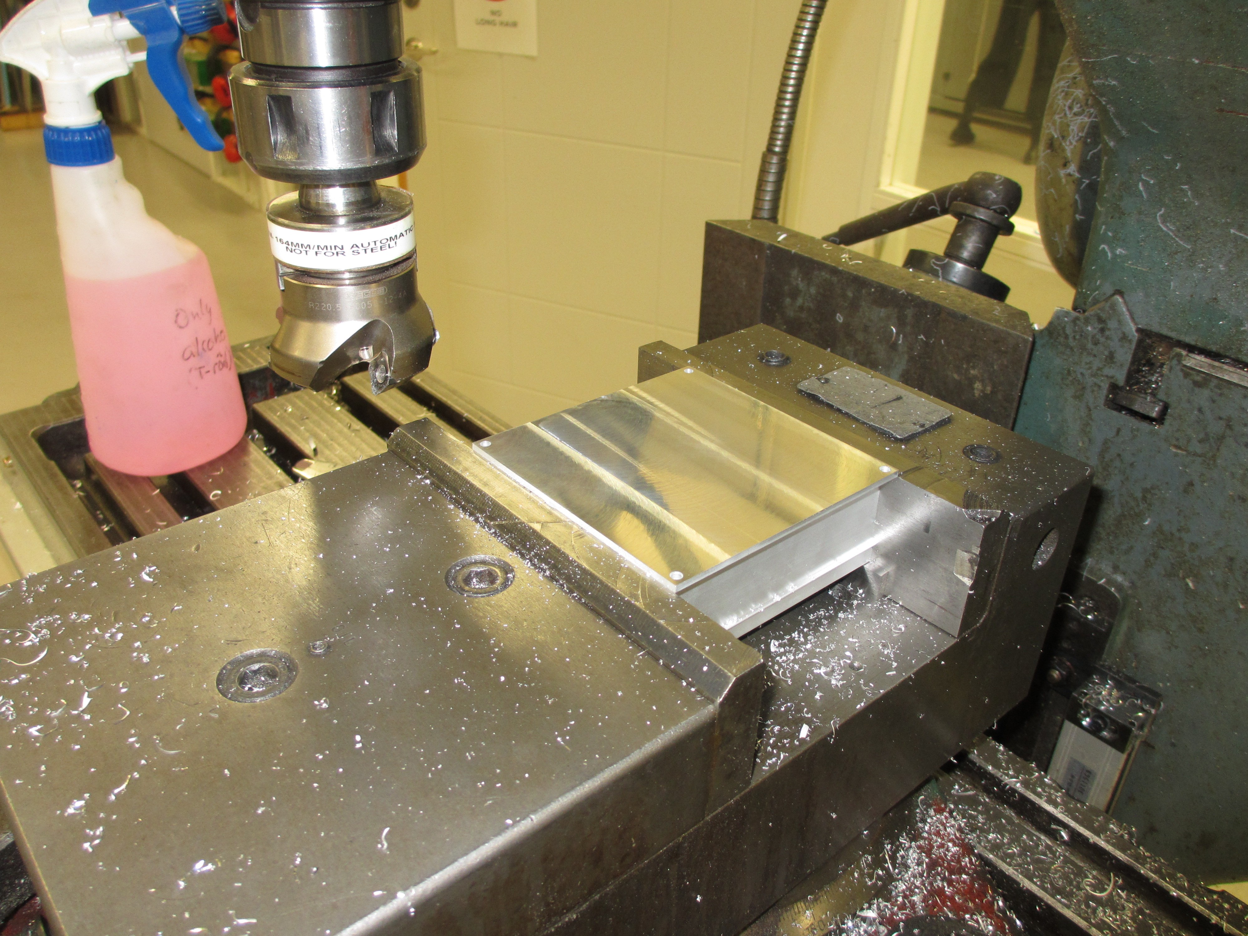
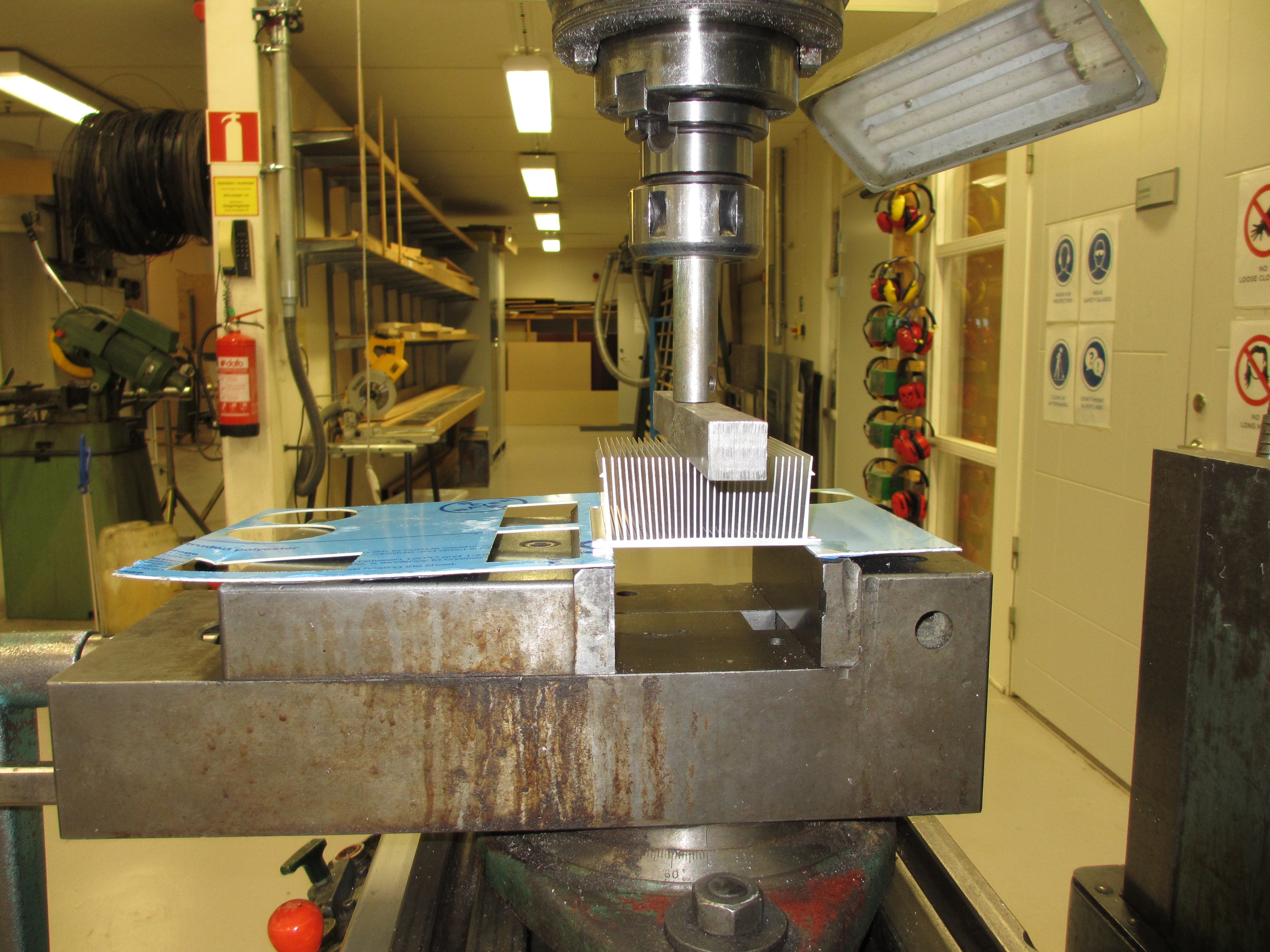
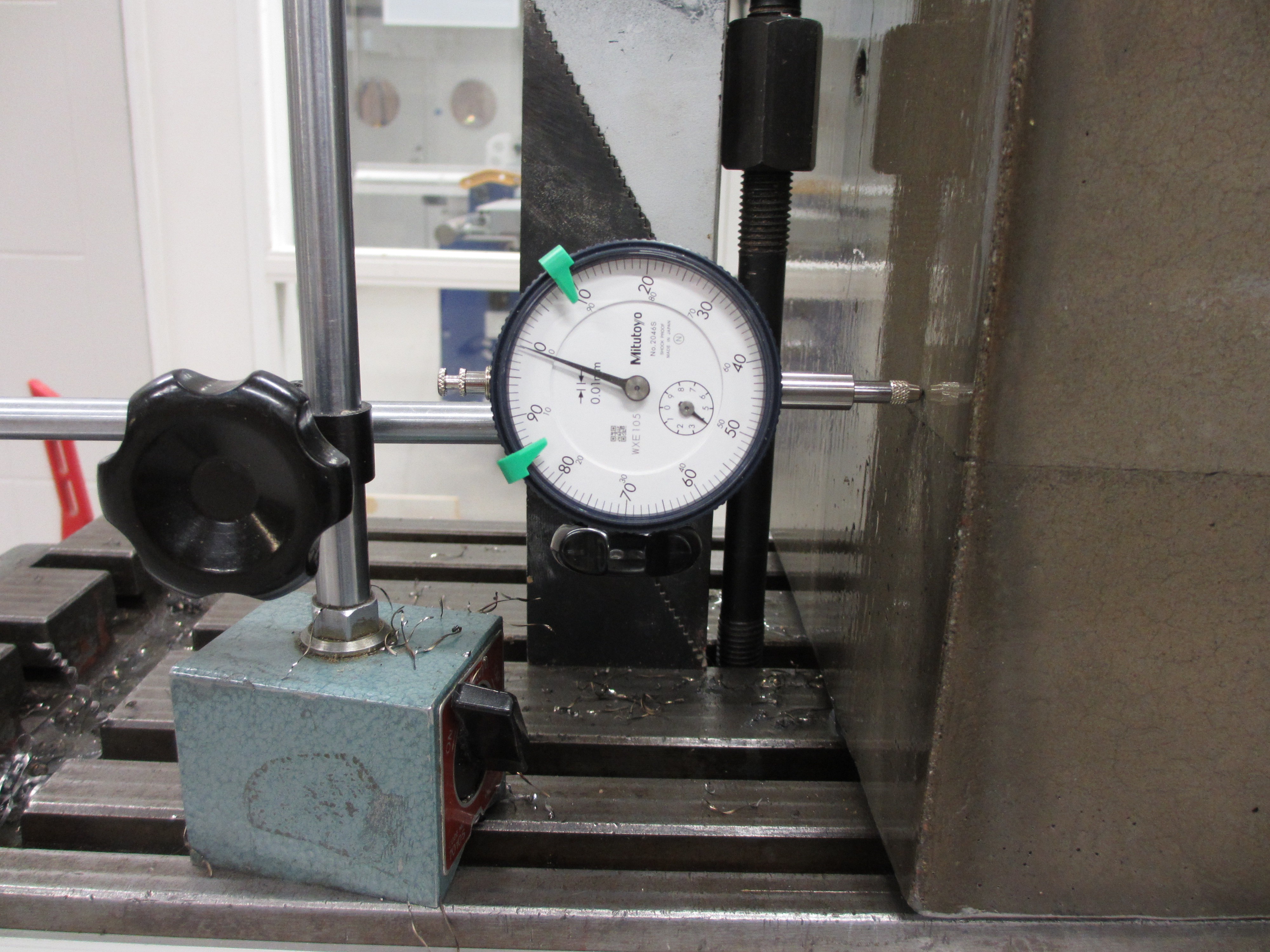
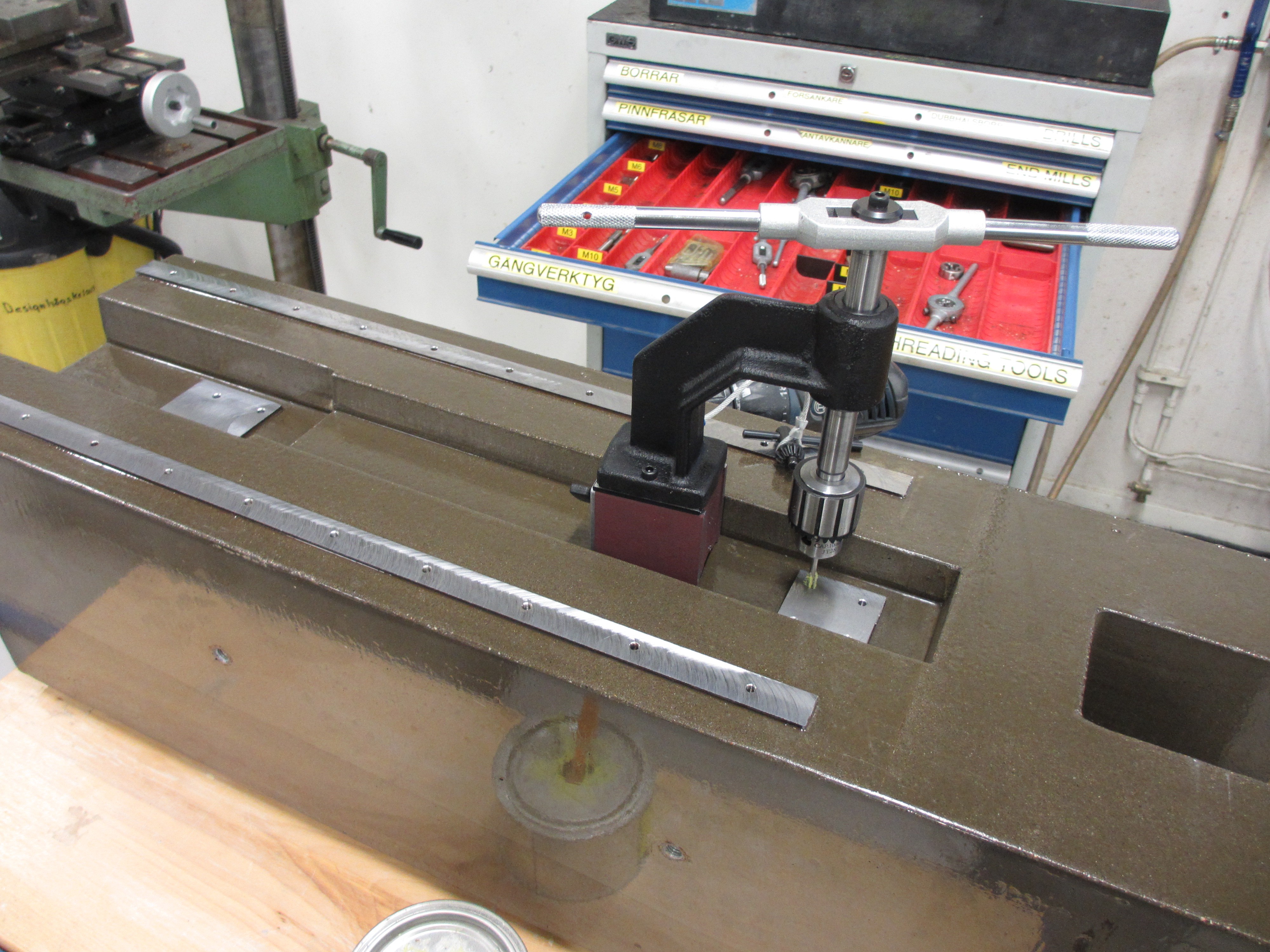
 To avoid twisting or bending the tower while clamping, and thus loosing precision, it is clamped down on three small plastic feet. Having only three points of contact, and placing the clamps right above the supports, prevents the tower from warping under the clamping force.
 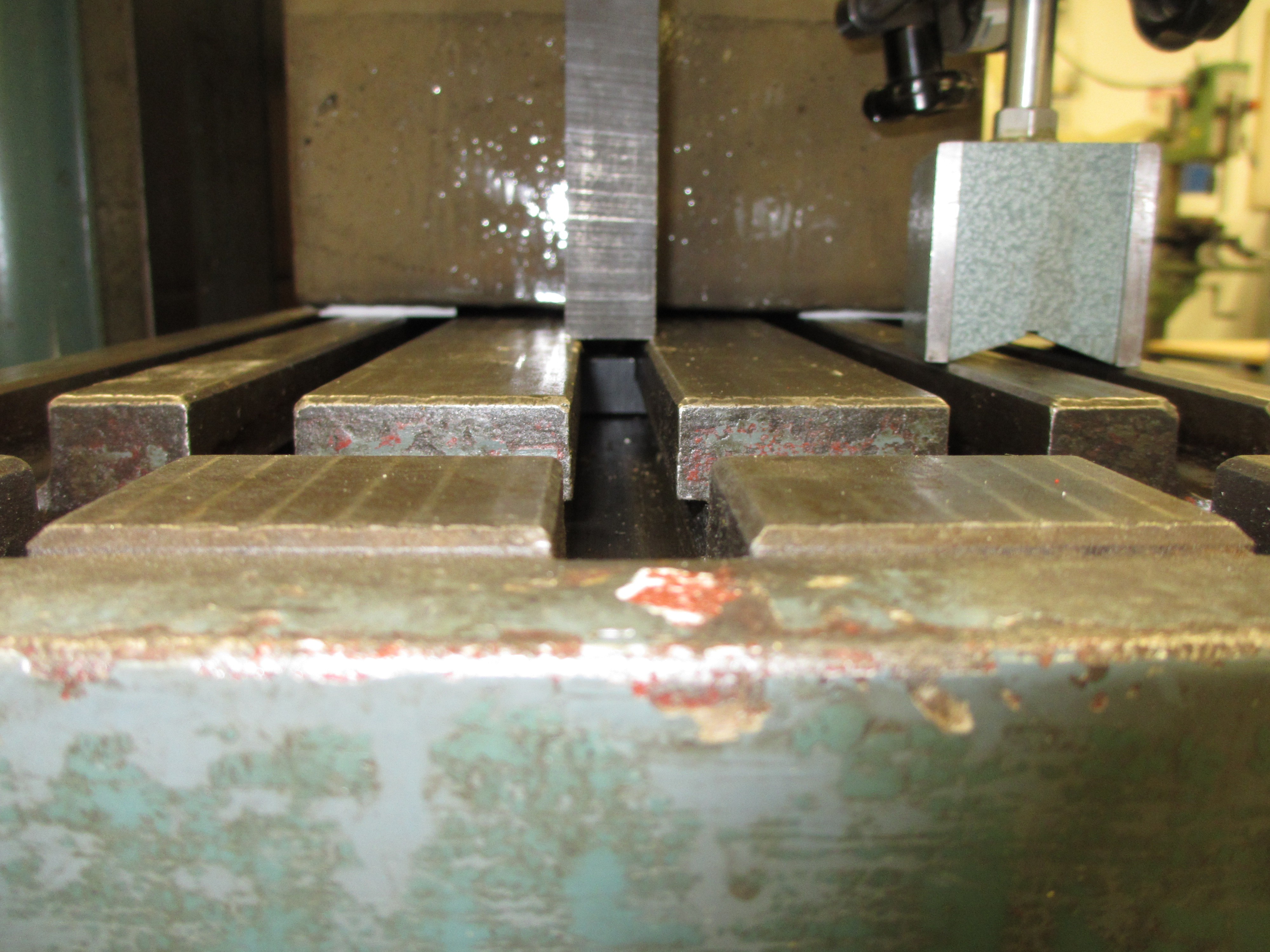 During machining, the block did move a bit. But only 0,01 mm in X and 0,02 mm in Y.
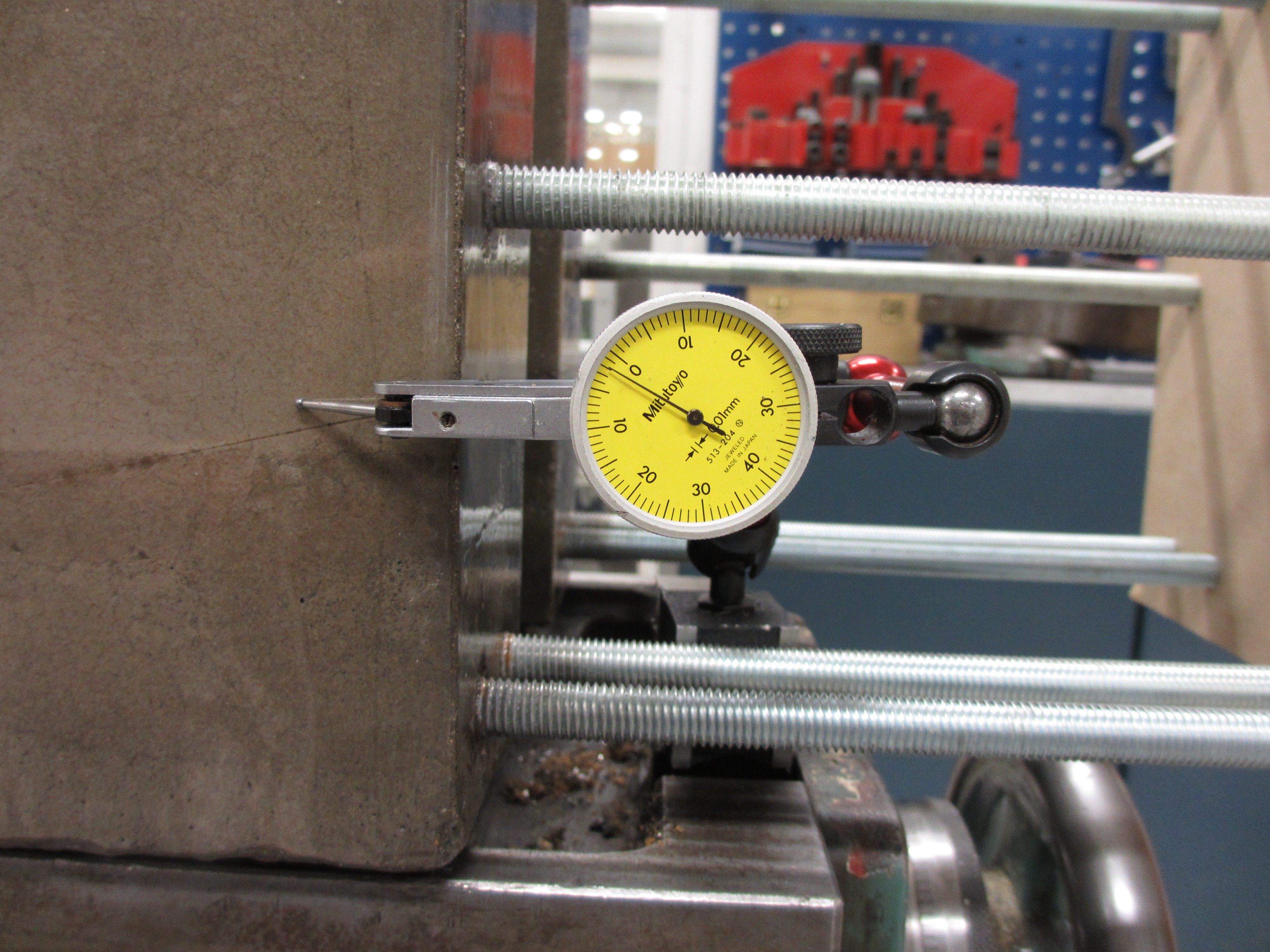
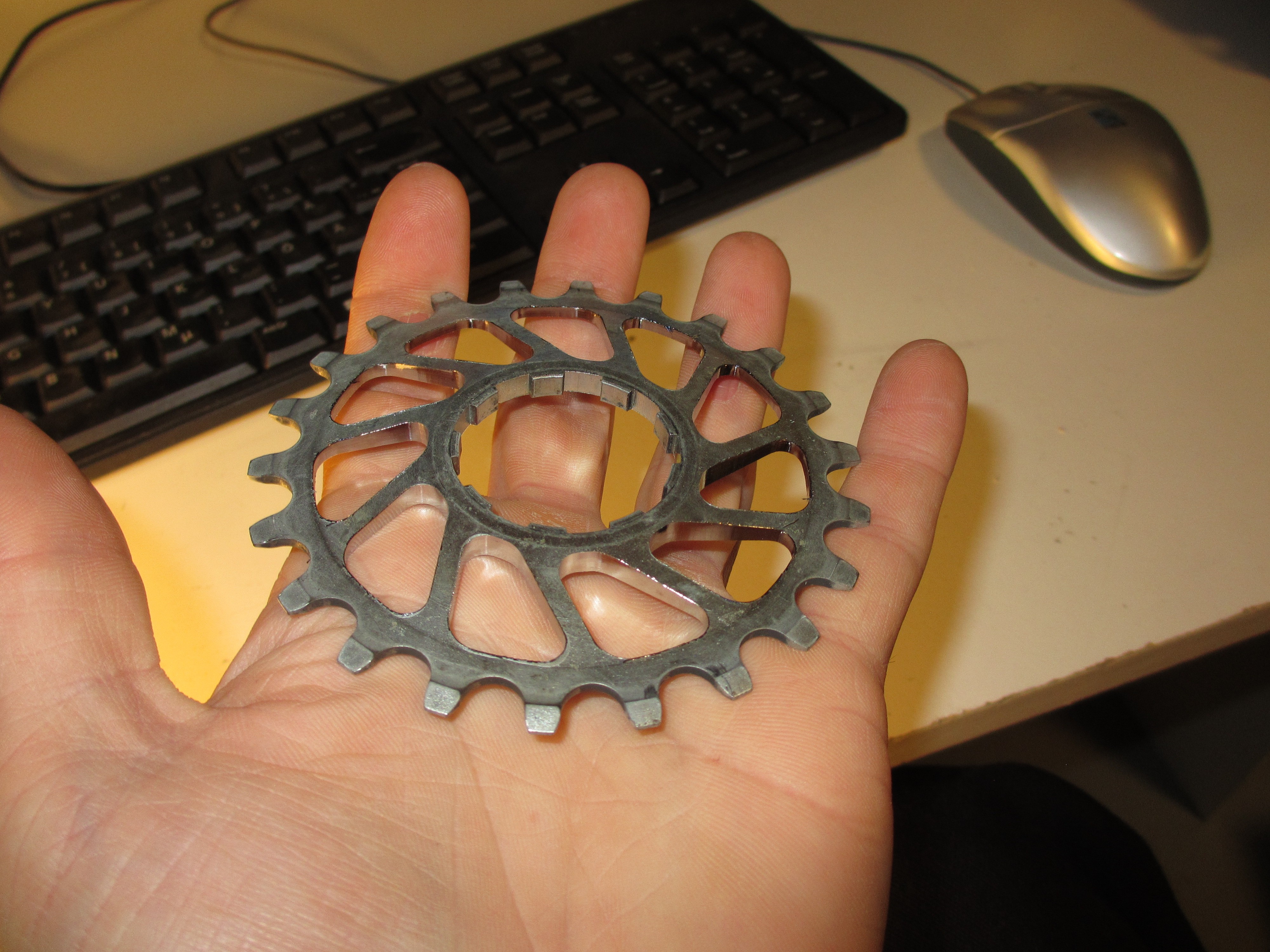
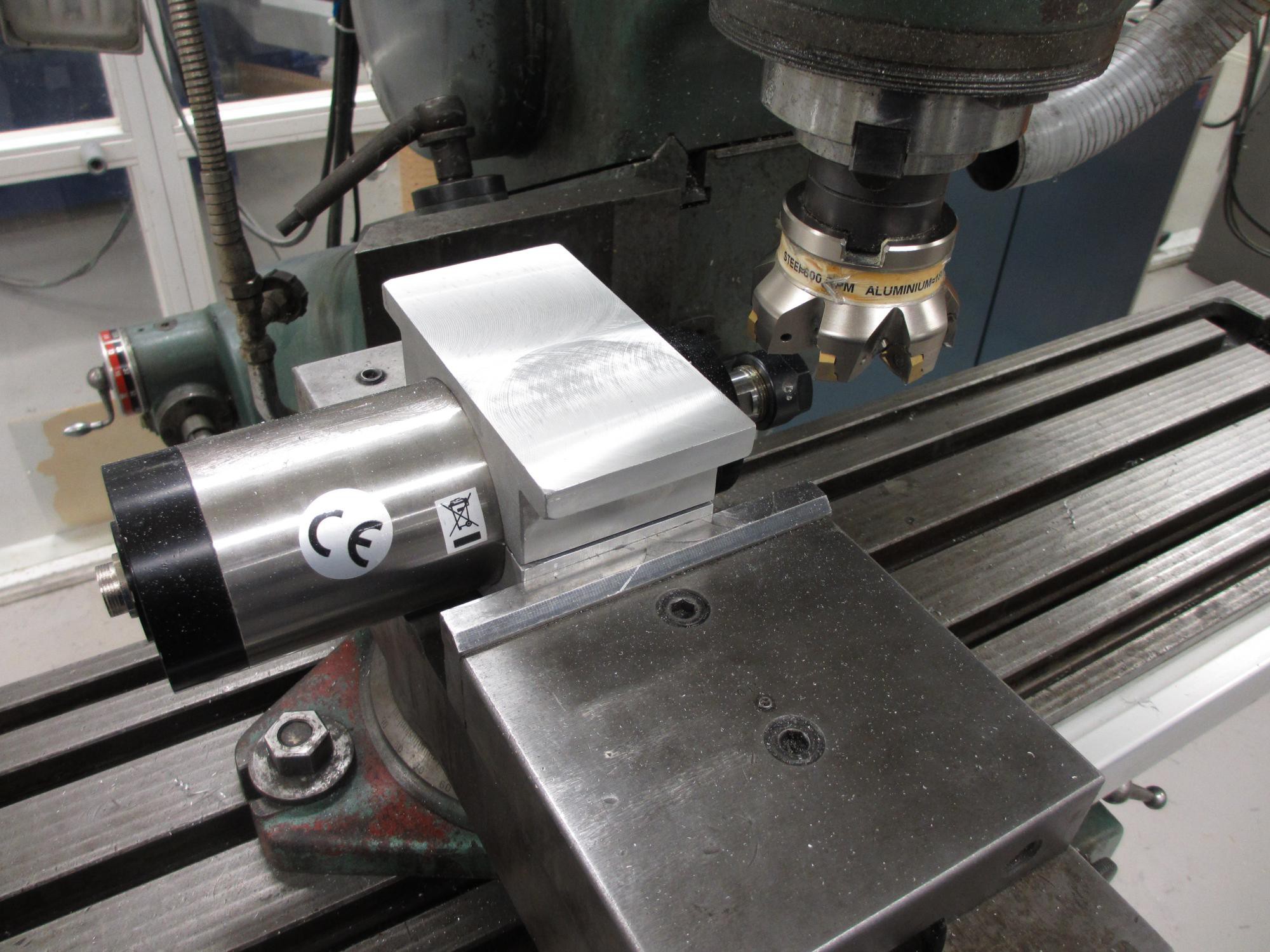
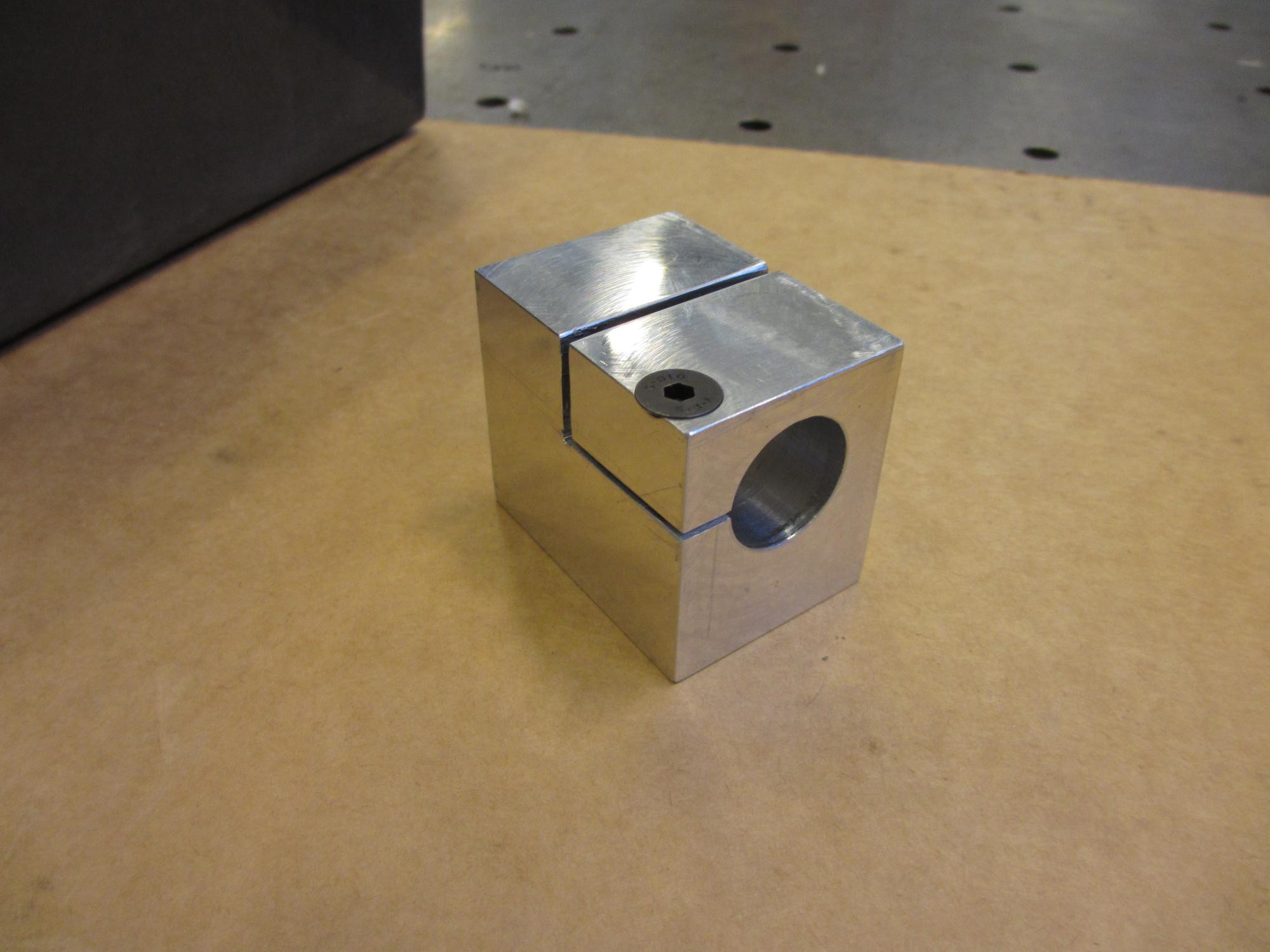
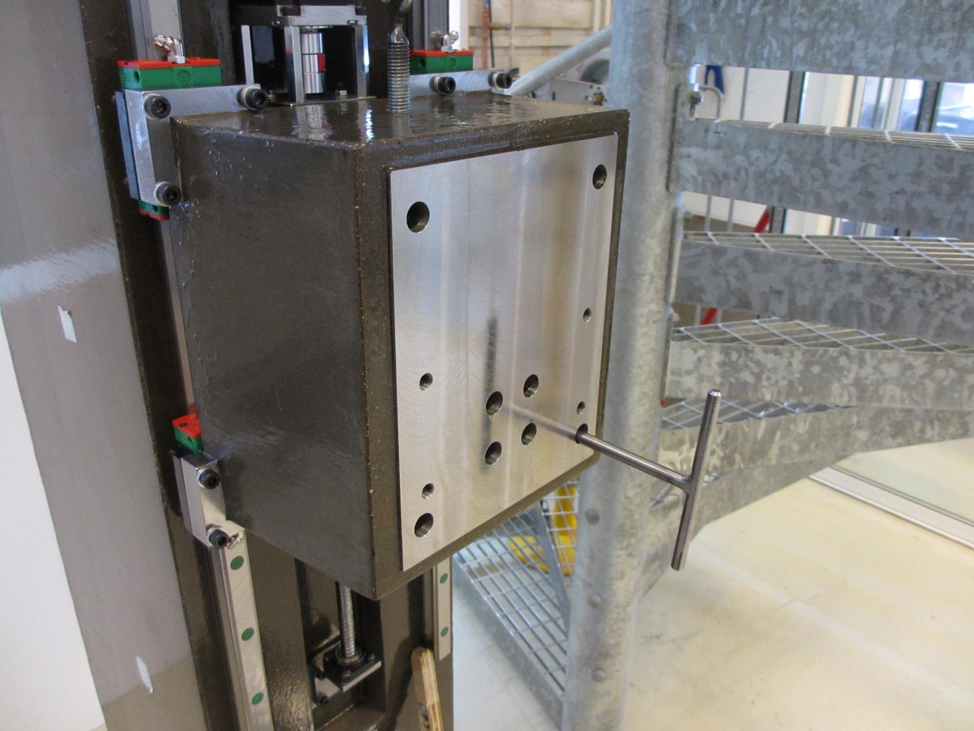
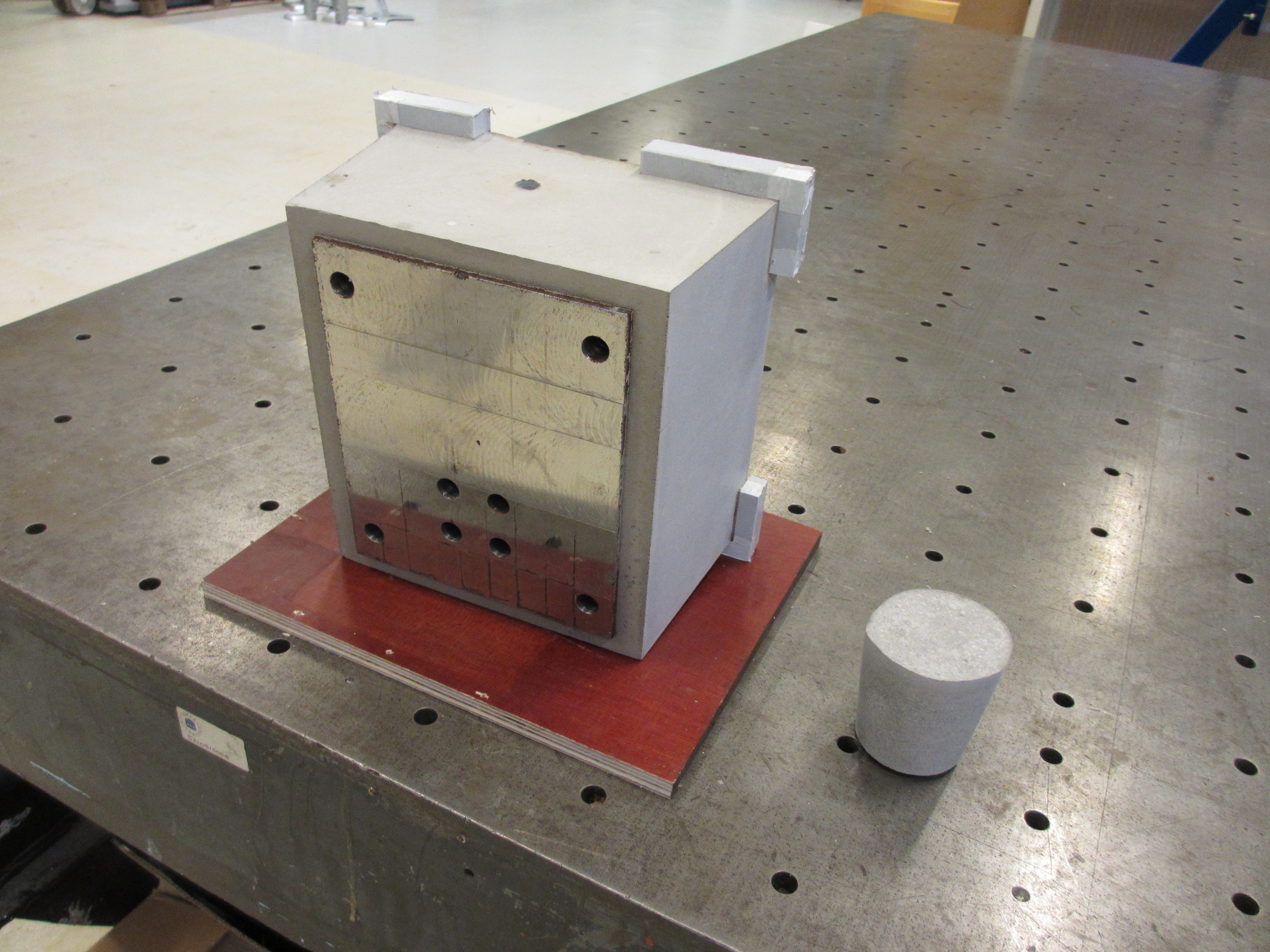
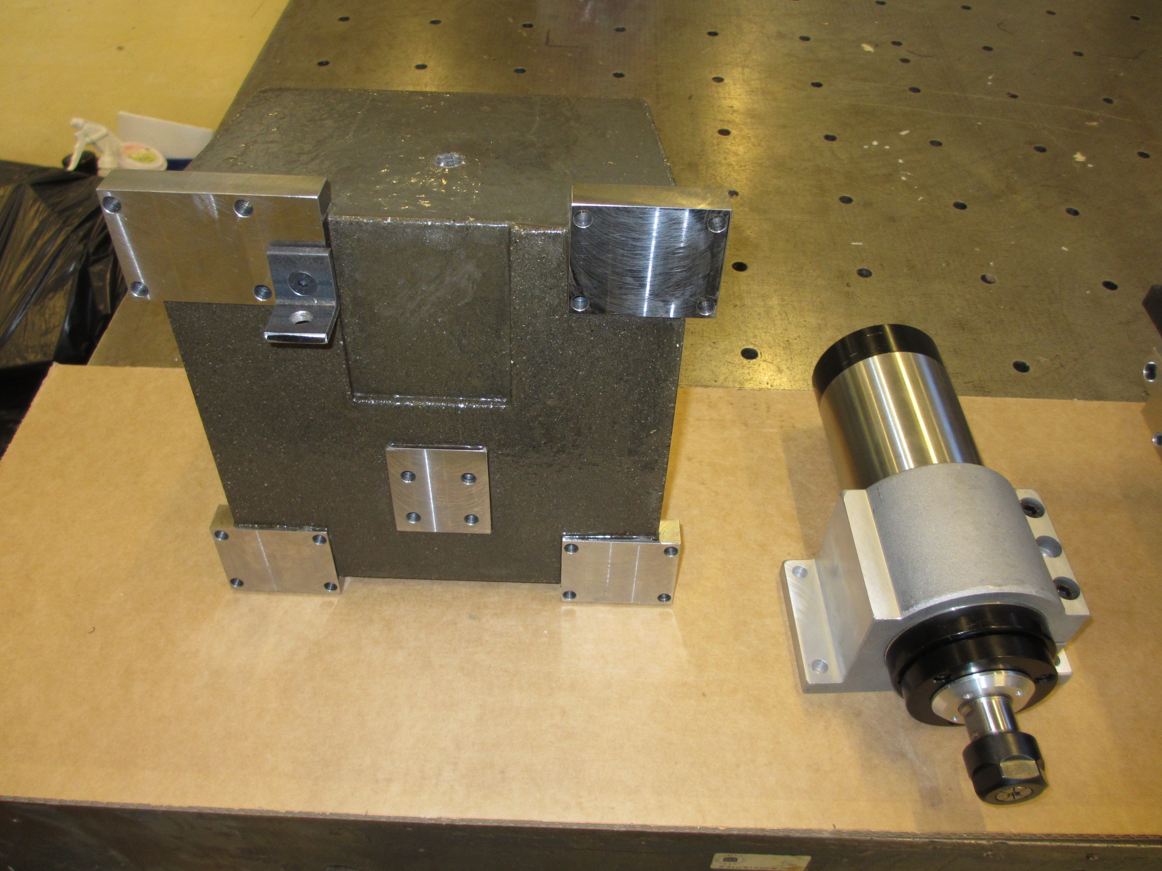
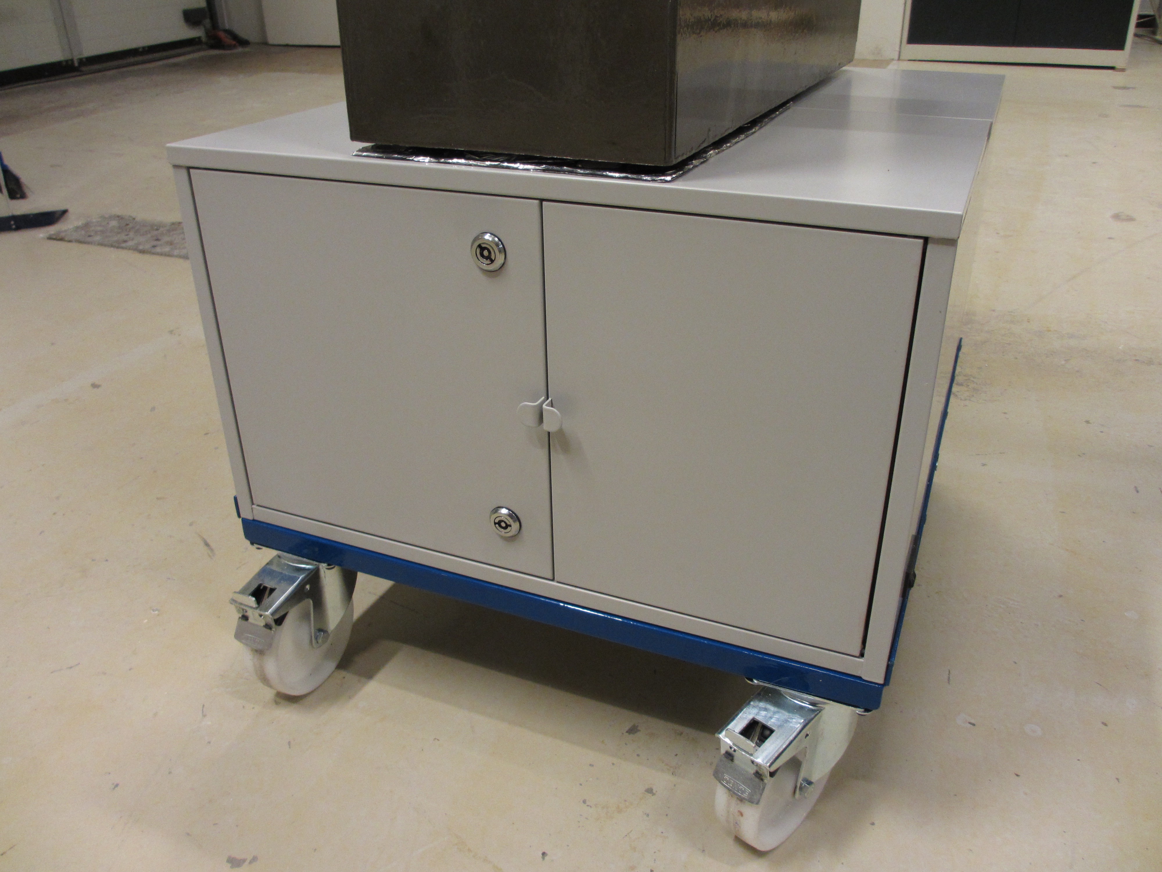
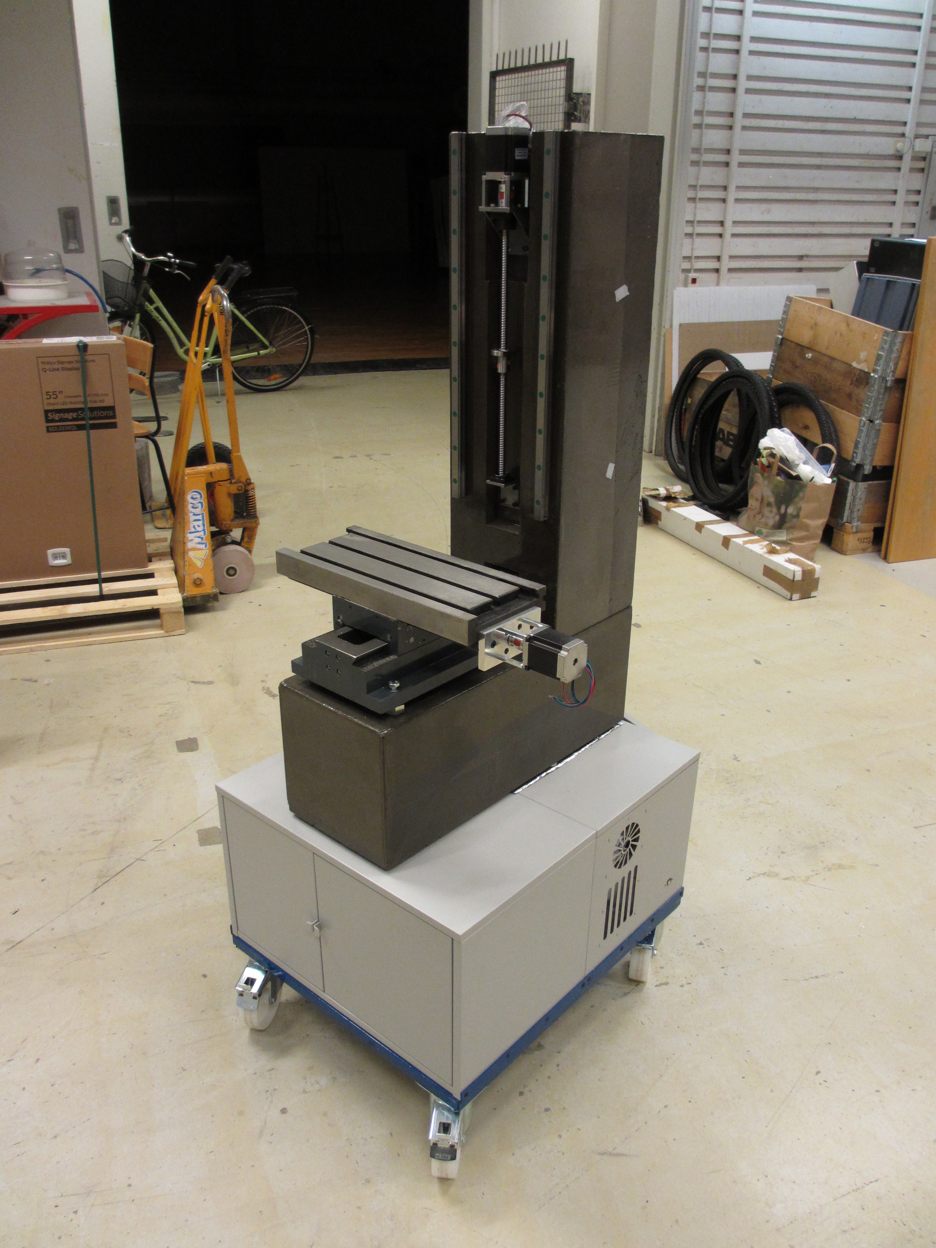
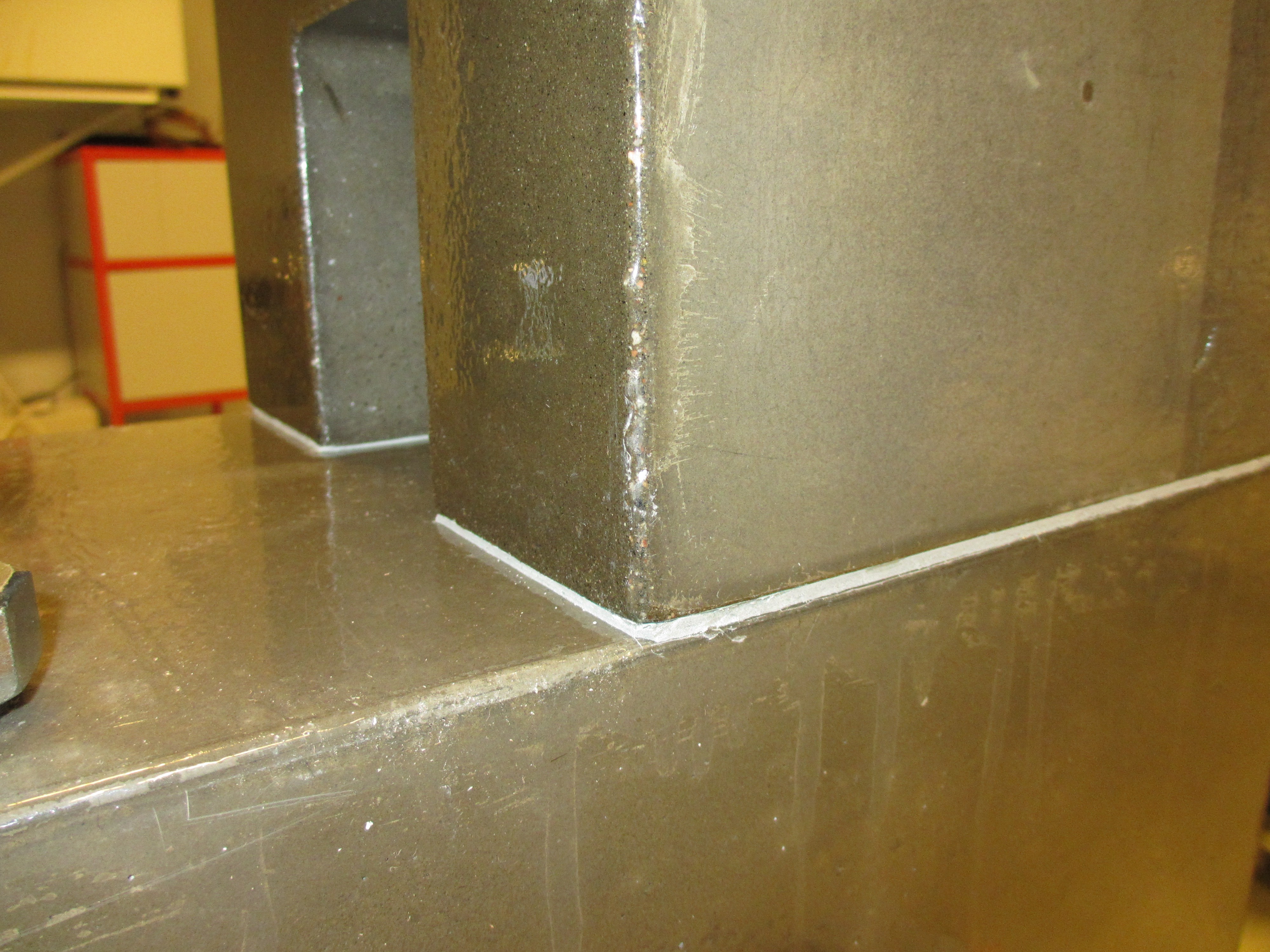
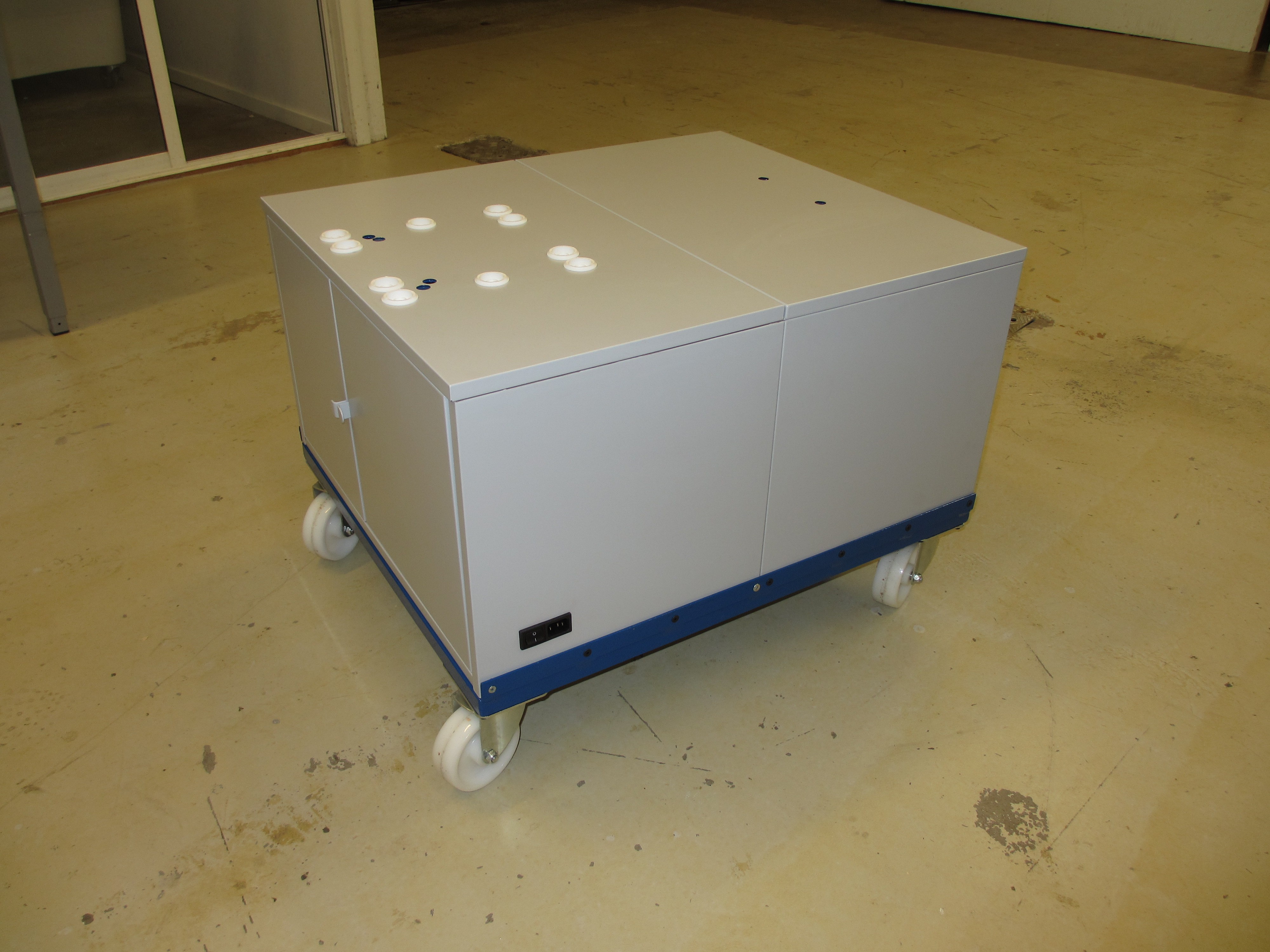
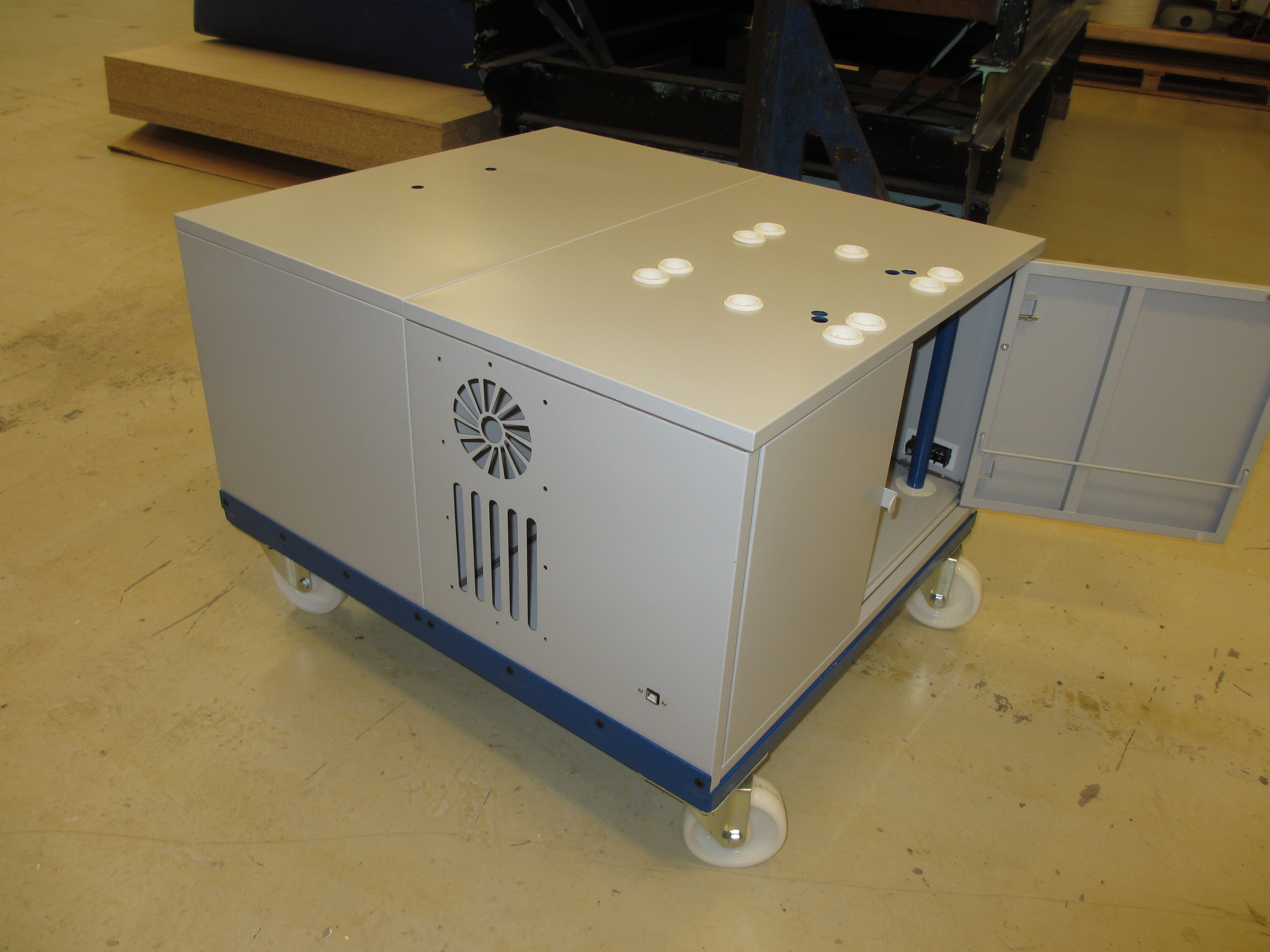
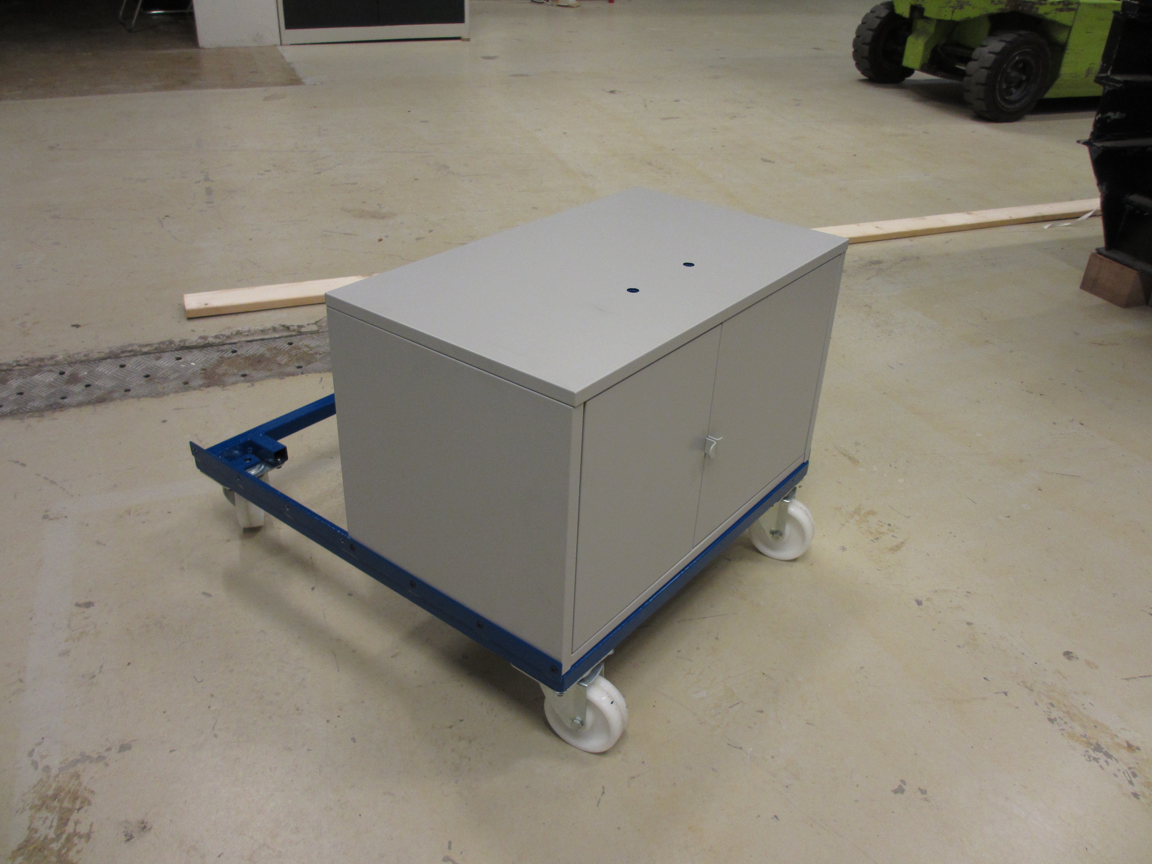
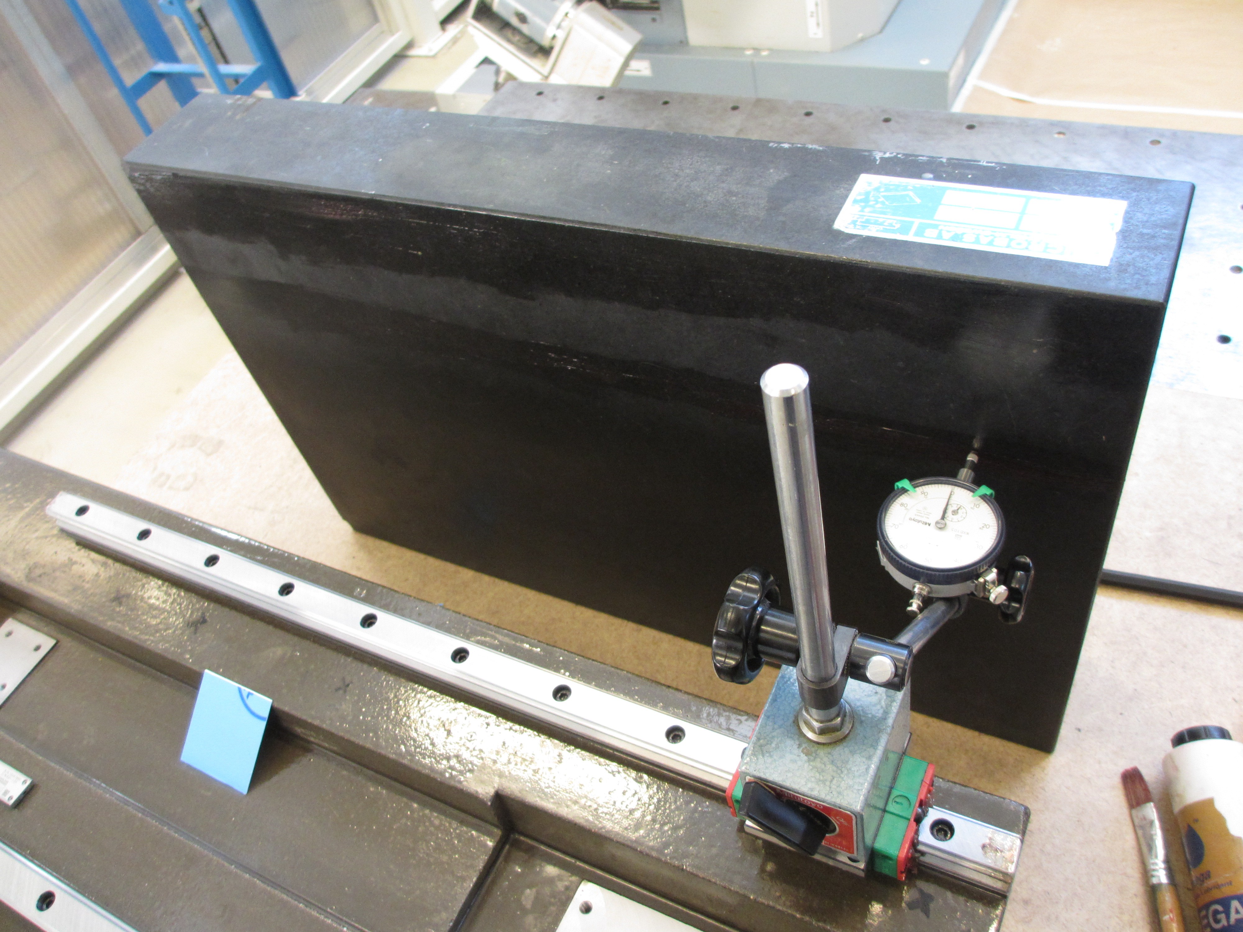
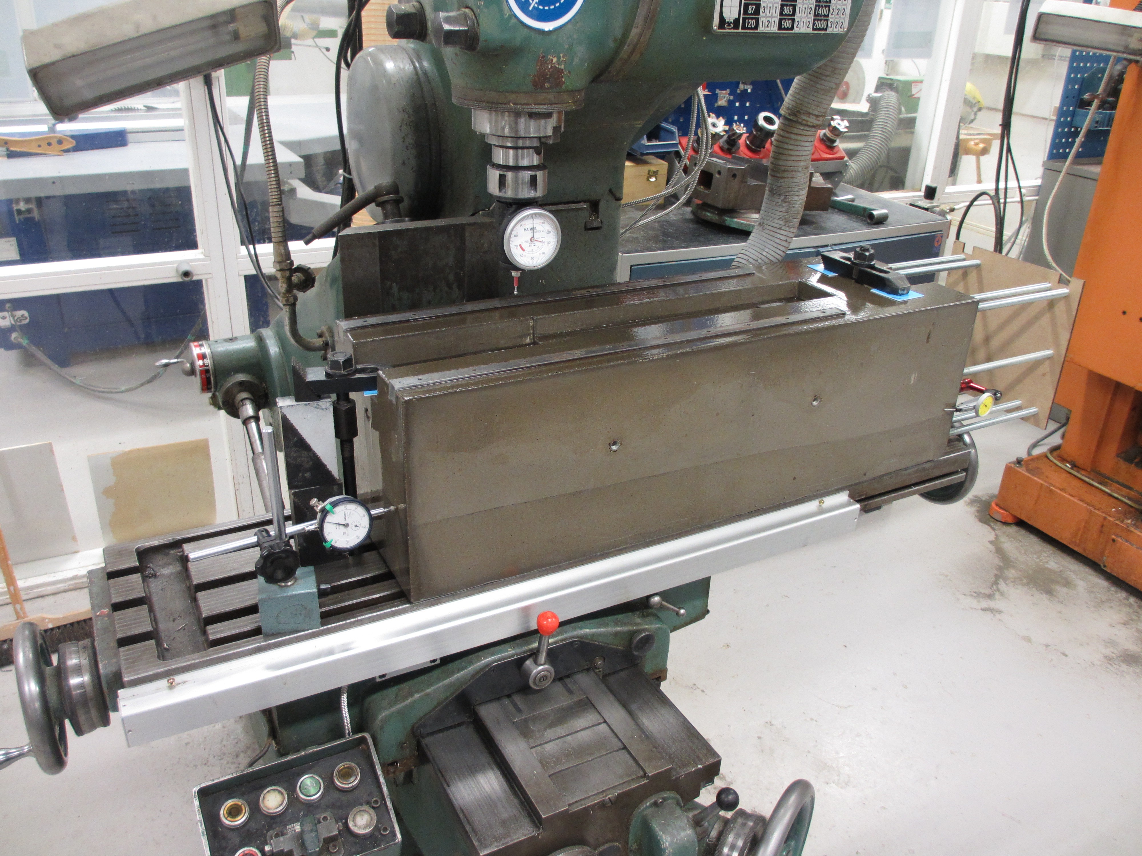
 And this is what it looks like!
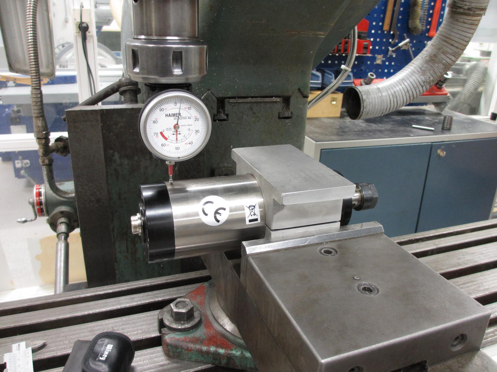
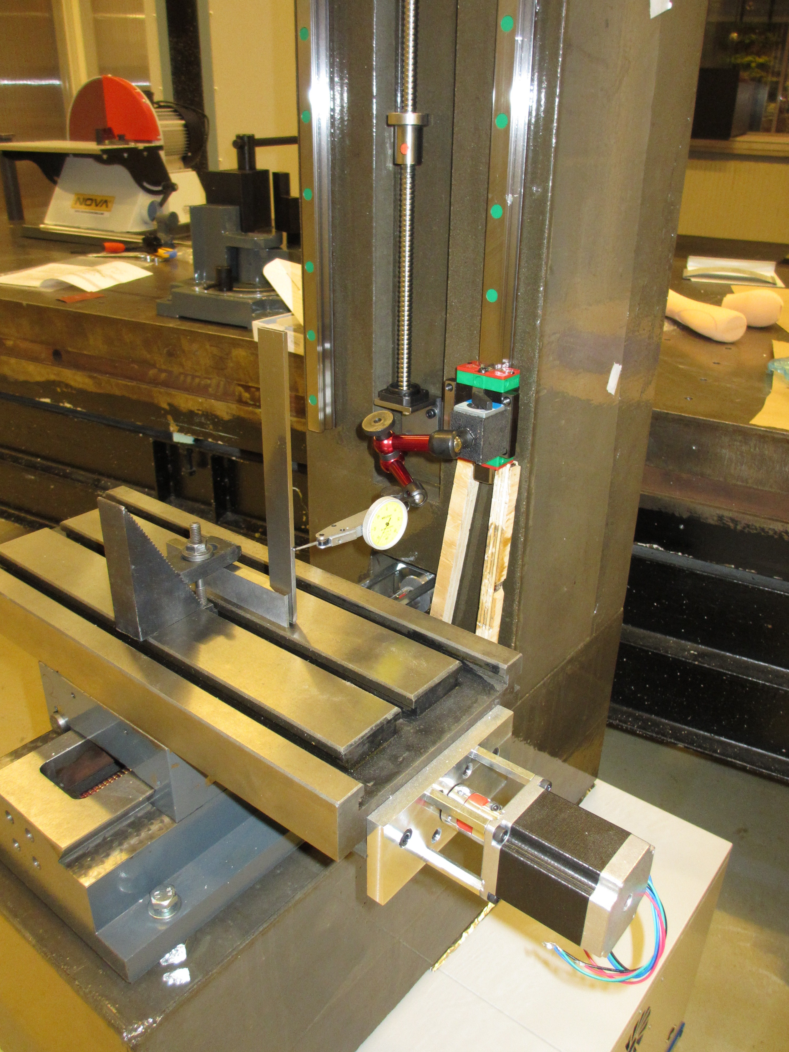
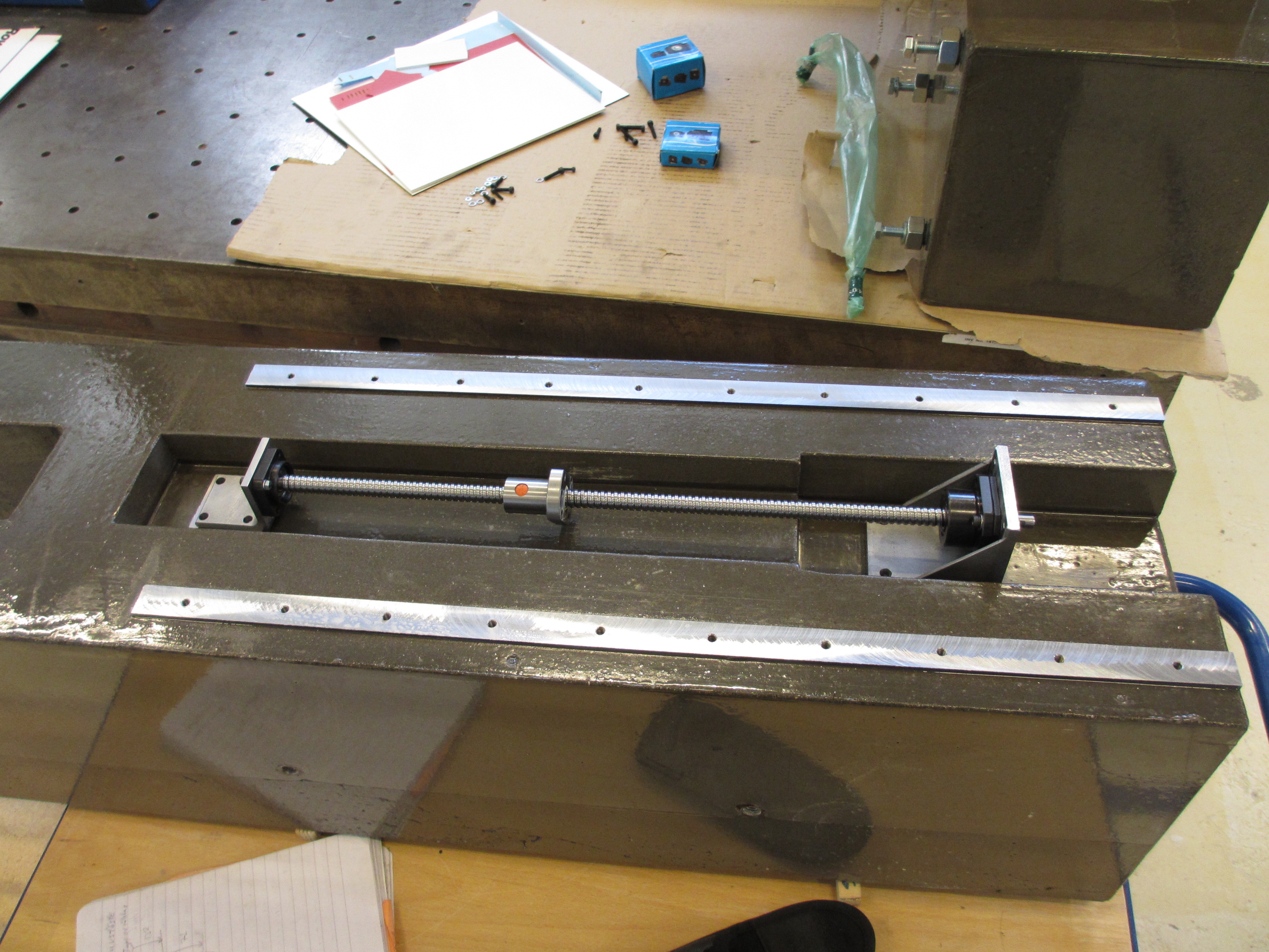 Next up is measuring the flatness of the rail mounts and mounting the rails.
 rawe
rawe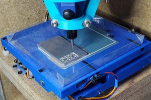
 Paul McClay
 zittware
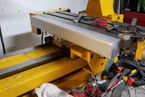
 Alastair Young
Bravo!
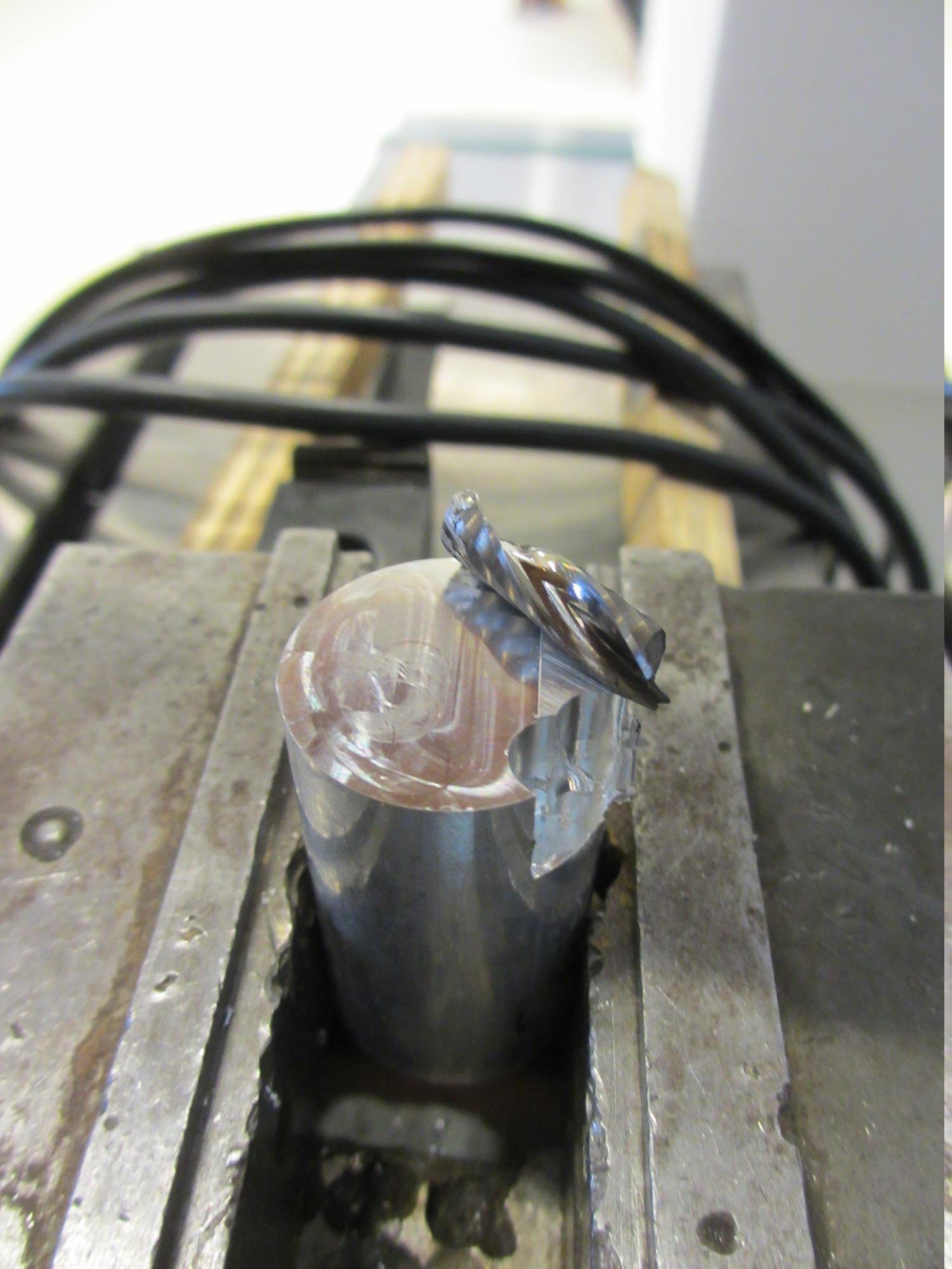
As for your hardened steel milling.. 1mm depth of cut is a lot for any trochoidal milling path. I think this little spindle and tool would zip along happily at 1/4 of that with an increased feed rate. Be careful next time.. that sort of heat generation on plywood can be dangerous but top marks for using a vacuum to clean up and not an airline! :)