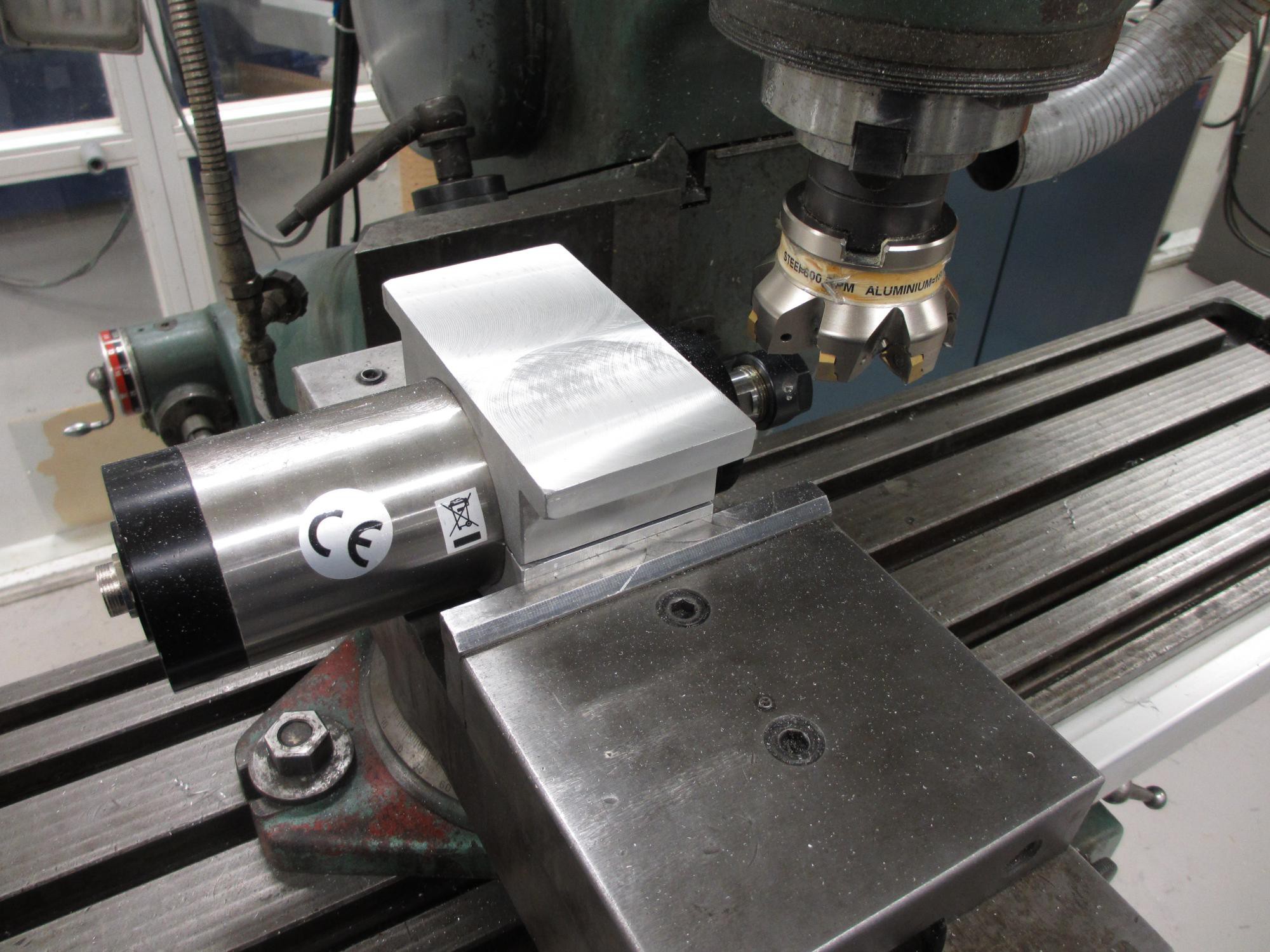
In parallel with making the "head" of the machine, I've been working on some other details. One thing was the spindle clamp. I purchased a ready-made clamp in cast aluminium, but found the precision to be quite low. So I remachined it a bit.
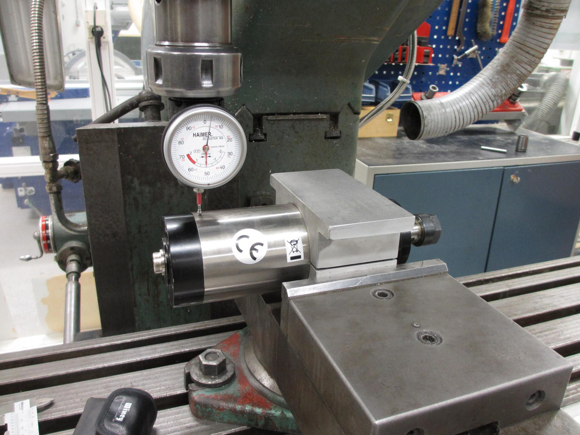
First I installed the spindle in the clamp, and dialed in the spindle to get it perfectly level. Then I machined it flat. But actually it wasn't that easy, I had to successively face all sides before I could clamp it properly since the overall straightness and squareness was so poor.
After machining I placed it on a granite surface plate and checked the result with a dial indicator.
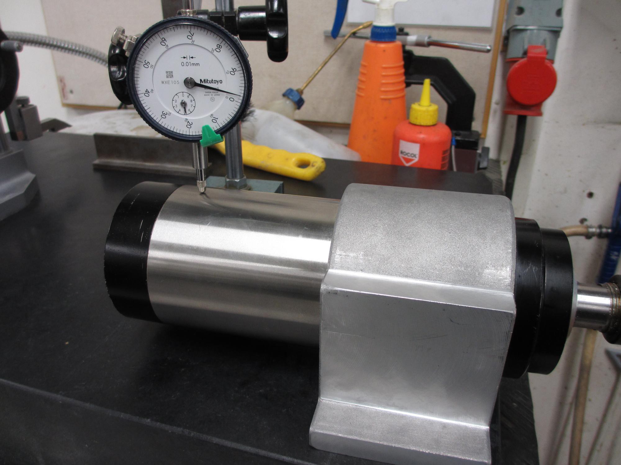
Unfortunately I found it to be out of alignment by about 0,02mm per 100mm, which is more than I consider acceptable. But when I reinstalled it in the milling machine and checked it with a dial indicator there, it seemed to be aligned. Nu use trying and failing again, so I'll wait until it is actually mounted on the CNC and see how it aligns there. If it does not align when properly mounted, I'll have to try again and compensate somehow.
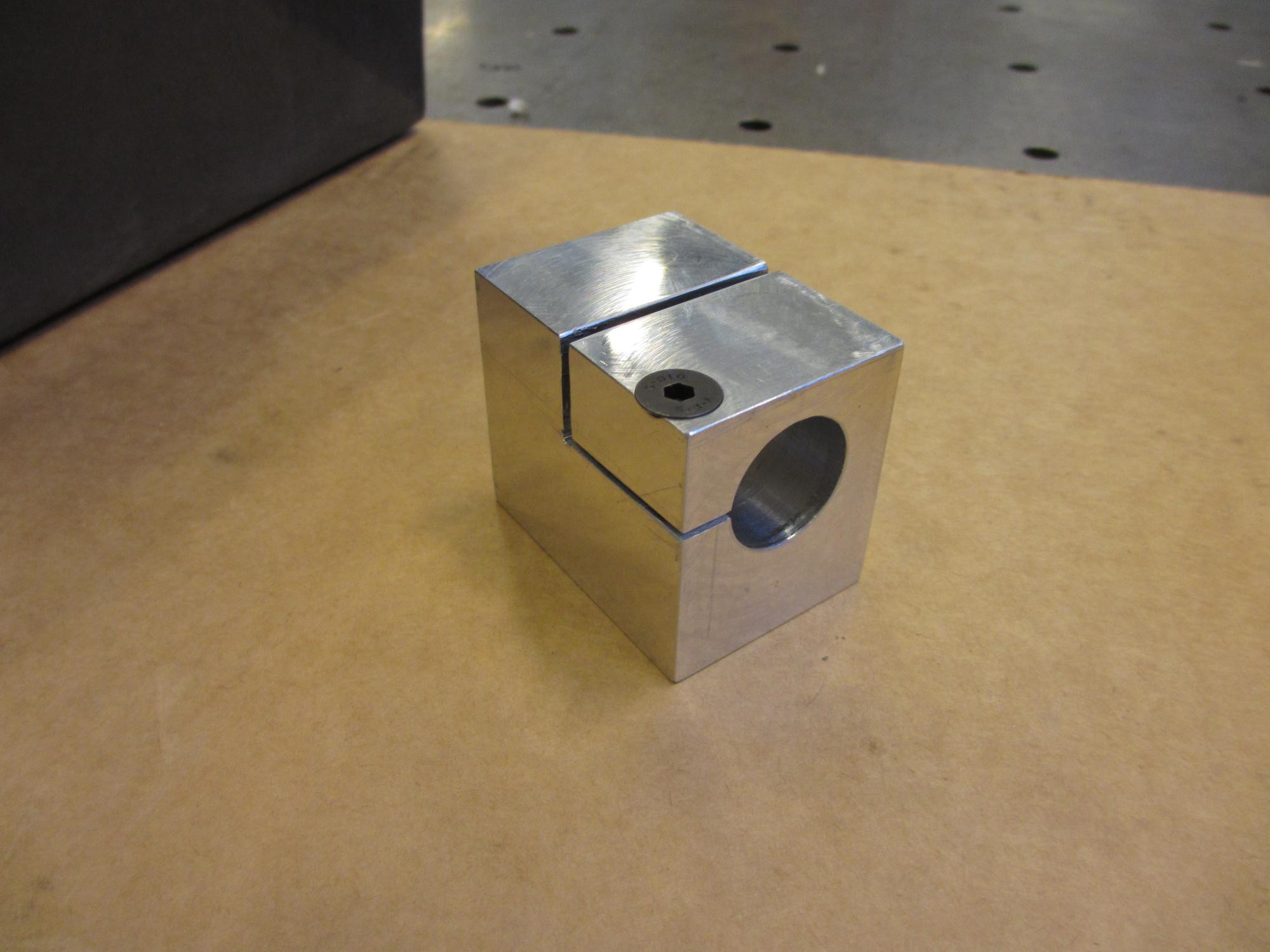
After working on the spindle clamp, I moved on to making the last ball nut block. I made this one slightly different from the previous blocks. This time I made room for a dedicated screw for clamping the preload-nut. The previous design used the same screws for mounting the block and for clamping the rotating nut, which made it a bit difficult to get the right preload during assembly.
I also wanted proper connectors for my stepper motors, which only had 4 wires sticking out of it. I figured somebody must already have done this, and indeed I found files on thingiverse for covers that match gx16 connectors (https://www.thingiverse.com/thing:2481149). But beware that you may need to mirror the part to fit your particular motor! (as I had to do).
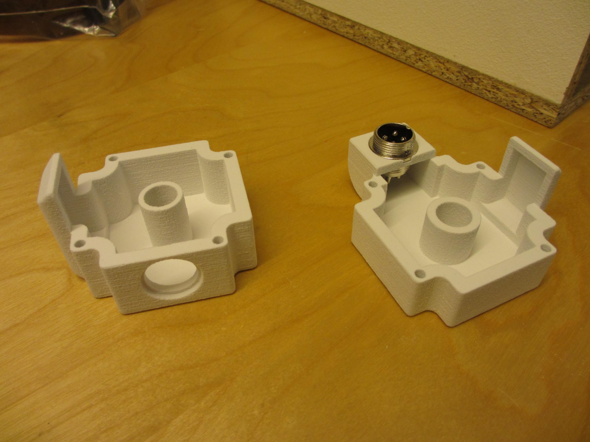
They printed well on our Z-corp plaster printer. Plaster may not sound like a good material, but it's cheap and temperature resistant, which is a good thing since they will be mounted on stepper motors that can get quite hot. After infiltrating the plaster with epoxy it gets more than enough strength.
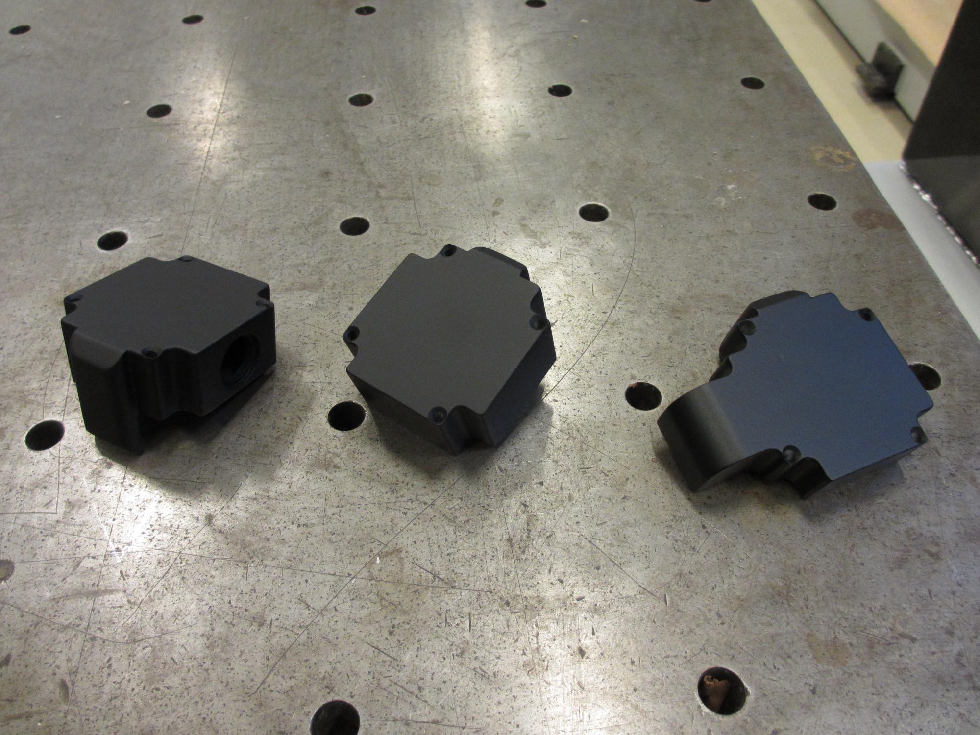
I also sanded and painted the parts, after which they look really good. If you look closely you can also see that I countersunk the holes for the screws.
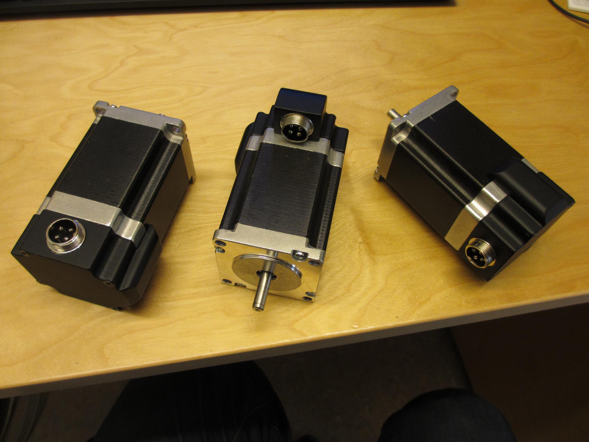
This is what they look like with the covers and connectors in place.
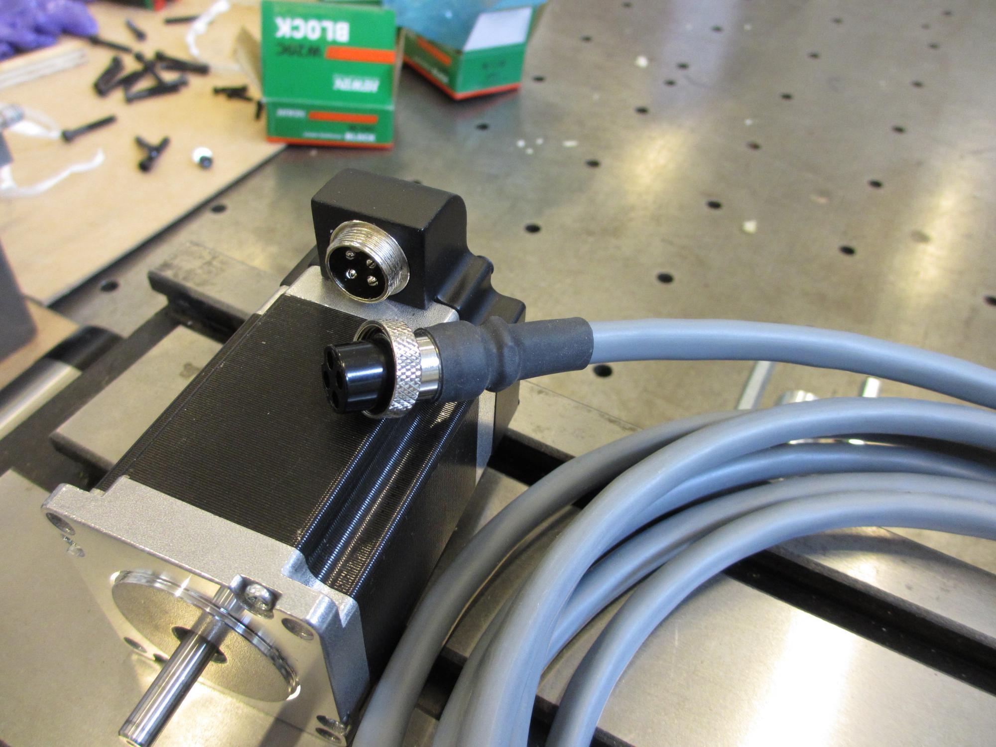
And this is a closeup of one of the motors along with the first cable I've assembled. Looks great! The cables are a bit overkill at 0,75mm2, but it was either that or 0,2mm2 (which should actually be enough, but only just. So i went with these). I got this cable at a clearance sale on elfa.se.
Now it's time for some assembling!
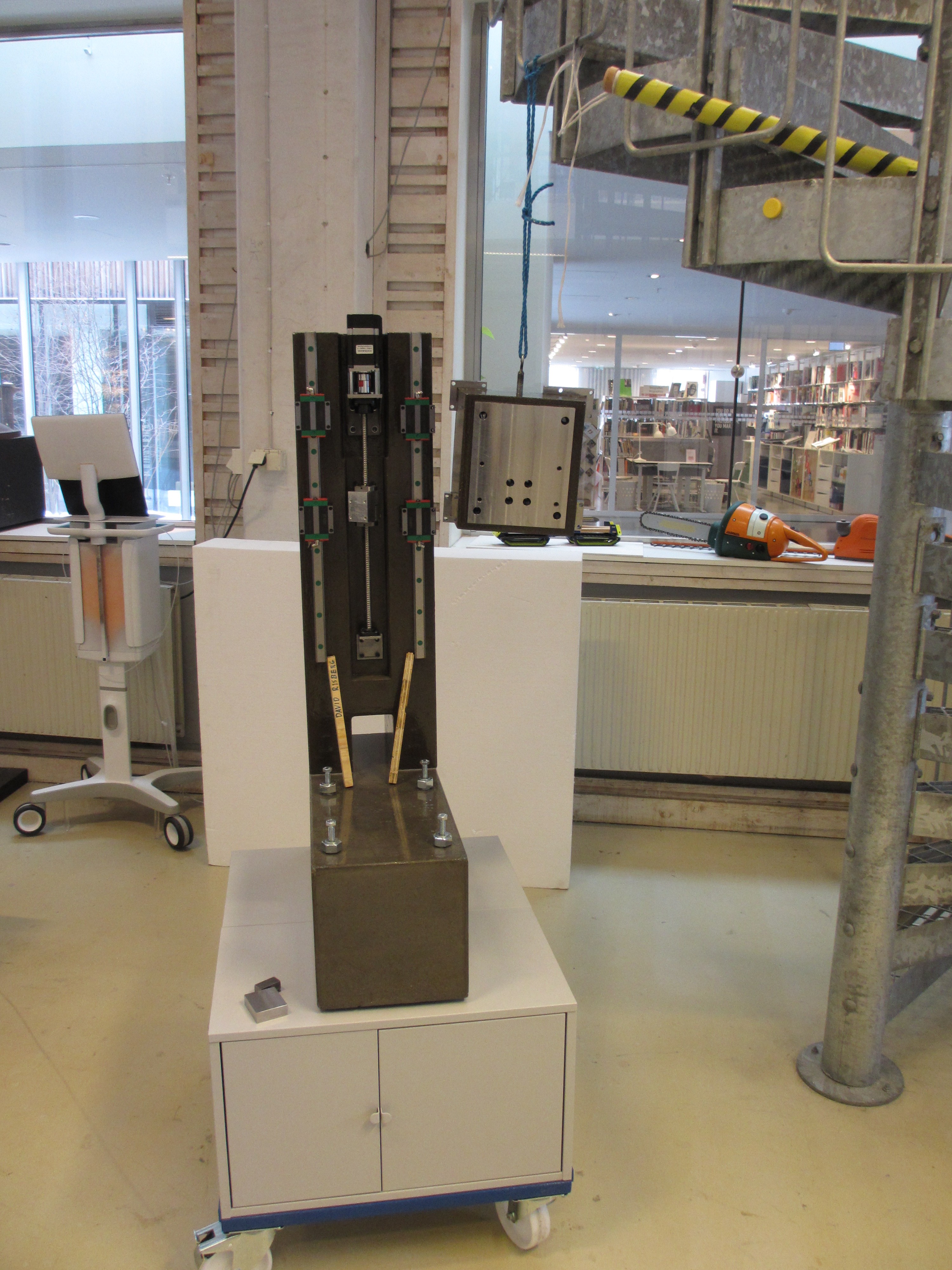
I started by assembling and greasing the ball screw assembly and the linear rail carriages. Since the "head" is quite heavy, I hung it from a rope at about the right height so I wouldn't have to hold it up while inserting the scews. This made it very easy to get everything in place.
But to fasten the last screws I needed a very long allen key, which I did not have. So I tried making one by cutting the tip from an allen key and welding it to a roundbar. I even turned down the weld in the lathe and polished it a bit to make it look good. With this tool it was very easy to get the screws in place through the deep holes in the head
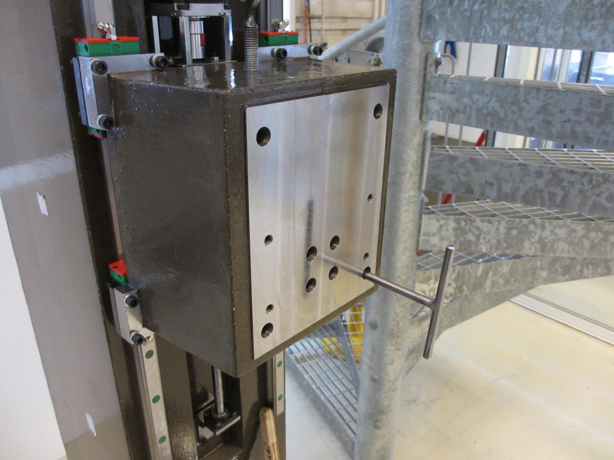
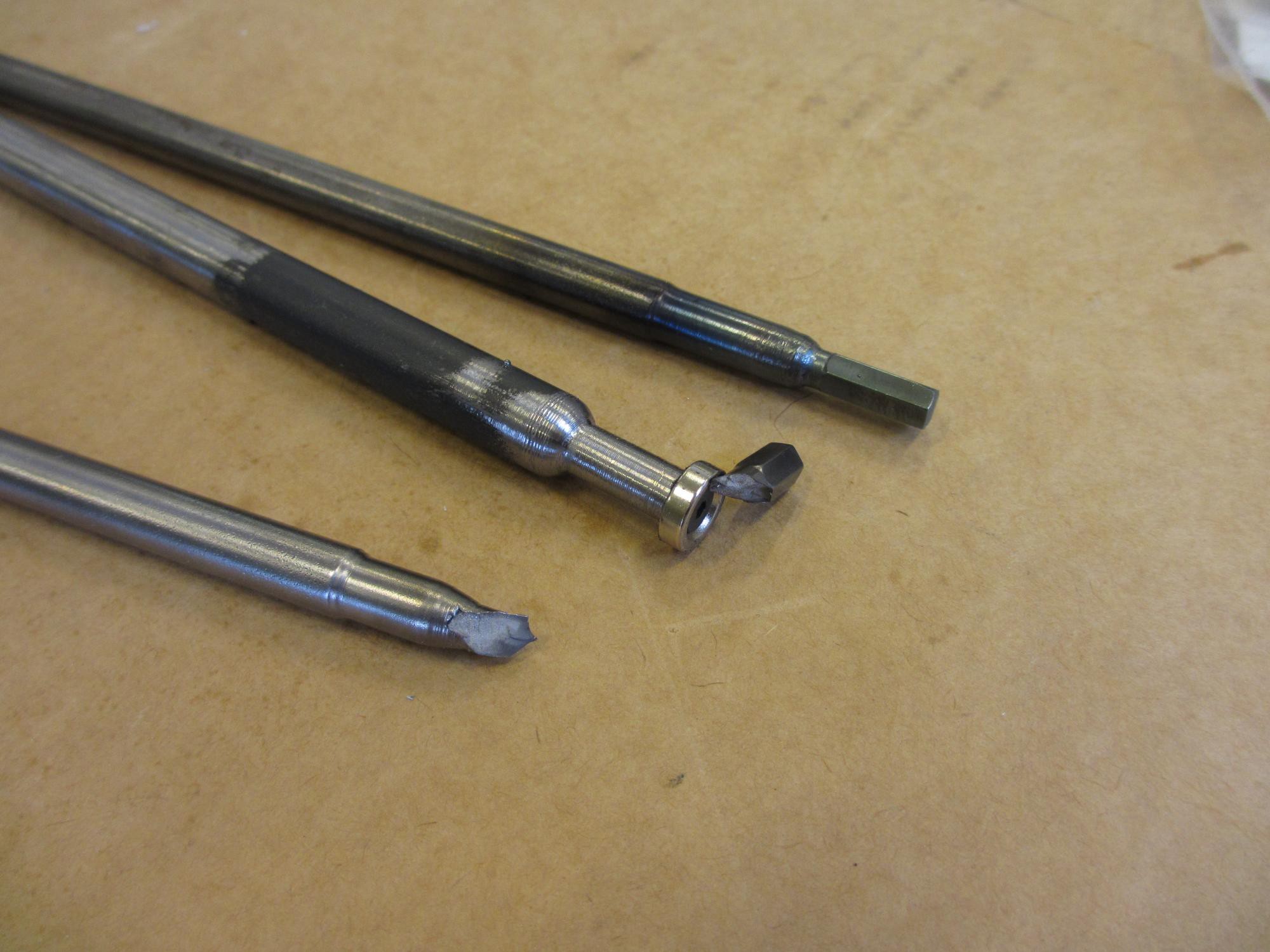
But when I applied more torque to fasten the screws properly, it immediately shattered. Probably because of uneven hardness after welding So I had to make a new one, but this time I tried hardening and tempering it with primitive means. I heated the tip with a blowtorch to an orange glow and quenched it in water. Then i brushed the metal clean and heated it until it turned blue (having a clean metal surface is important to be able to see the change in color). This time it held up to the full torque needed with ease. It seems I tempered it a bit too warm, since I could see some very slight deformation on the corners after fastening. But it worked! Below is a picture of (from top to bottom) the new tool, a roundbar with a magnet tip holding the fragment from the first tool, and the rest of the first tool.
This is a big moment for me by the way; the machine is finally starting to look like something! Check this out:
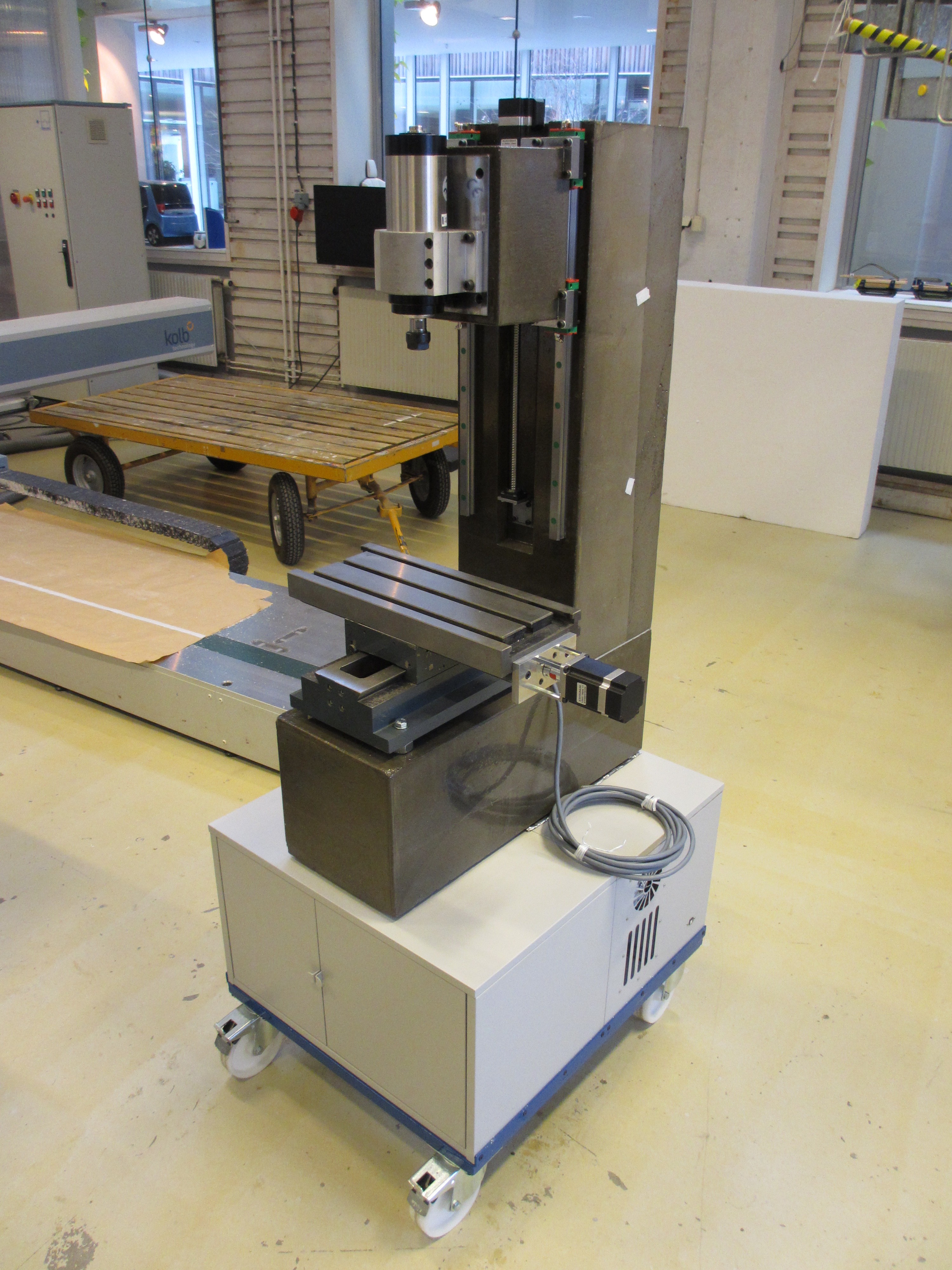
At this point I also noticed that the head does indeed fall down when the stepper motor is not powered. So now I've ordered the gas spring I mentioned in the last post to counteract the weight.
All that's left now is installing and configuring the electronics! Then building an enclosure of course, I won't have it any other way. But first I want to get it moving!
Discussions
Become a Hackaday.io Member
Create an account to leave a comment. Already have an account? Log In.