I've spent the last couple months on this project trying to get the photo output to be as detailed and high-quality as possible, and I'm pretty happy with the results. The results are still far from perfect, but they've improved considerably since the last photos I posted. In my next couple build logs I'll break down some of the different changes that I've made.
Camera Alignment
One of the largest issues with my photos that caused viewer discomfort was vertical parallax. Due to each camera having a slight tilt up or down from the horizontal axis, objects appearing in the one eye view would appear slightly higher or lower than their image in the other eye. I had created a manual alignment program that allowed me to use the arrow keys to move the images up and down to position them, but it took forever to get good results with this, especially when considering the three different possible axes of rotation.
My solution, emulating the approach of Google's Jump VR, was to use custom software to figure out the rotation of each camera in 3D space, and translate this to how the images should be positioned. I chose to use the brute force method - estimate the positions and then use an iterative algorithm (Levenberg-Marquardt) to correct them. The alignment algorithm is described below:
- Use guess positions and lens characteristics to de-warp fisheye images to equirectangular and convert to spherical projection
- Use OpenCV SURF to find features in the spherical images
- Match these features to features in images from adjacent cameras
- Keep features that are seen from three adjacent cameras
- Use the spherical and equirectangular matrices in reverse to figure out the original pixel coordinates of the features
- Set up camera matrices for each camera with 3D coordinates, 3D rotation matrix, and 2D lens center of projection (pixel coordinates)
- Begin parameter optimization loop:
- Begin loop through the features with matches in 3 images:
- Calculate the 3D line corresponding to the pixel at the center of the feature in each of the 3 images
- When viewed in the X-Y plane (horizontal plane, in this case), the three lines form a triangle. Calculate the area of the triangle and add this to the total error. This area should ideally be zero, since the lines should ideally intersect at one point.
- Calculate the angles of each line from the X-Y plane, and calculate the differences of these angles. Add this difference to the total error. Ideally, the difference between the angles should be almost zero, since the cameras are all on the X-Y plane and the lines should all be pointed at the same point.
- Figure out the derivatives of all of the parameters (angles, centers, etc.) with respect to the total error and adjust the parameters accordingly, trying to get the total error to zero
- Repeat until the total error stops going down
- Begin loop through the features with matches in 3 images:
This is a greatly simplified version of the algorithm and I left a number of steps out. I'm still tweaking it and trying to get the fastest optimization and least error possible. I also switched to the lens model in this paper by Juho Kannala and Sami S. Brandt. In addition to the physical matrix for each camera, the optimization algorithm also adjusts the distortion parameters for the lenses. Currently, I'm using the same parameters for all lenses but I may switch to individual adjustments in the future.
Also, here's a visual representation of the feature-finding process.
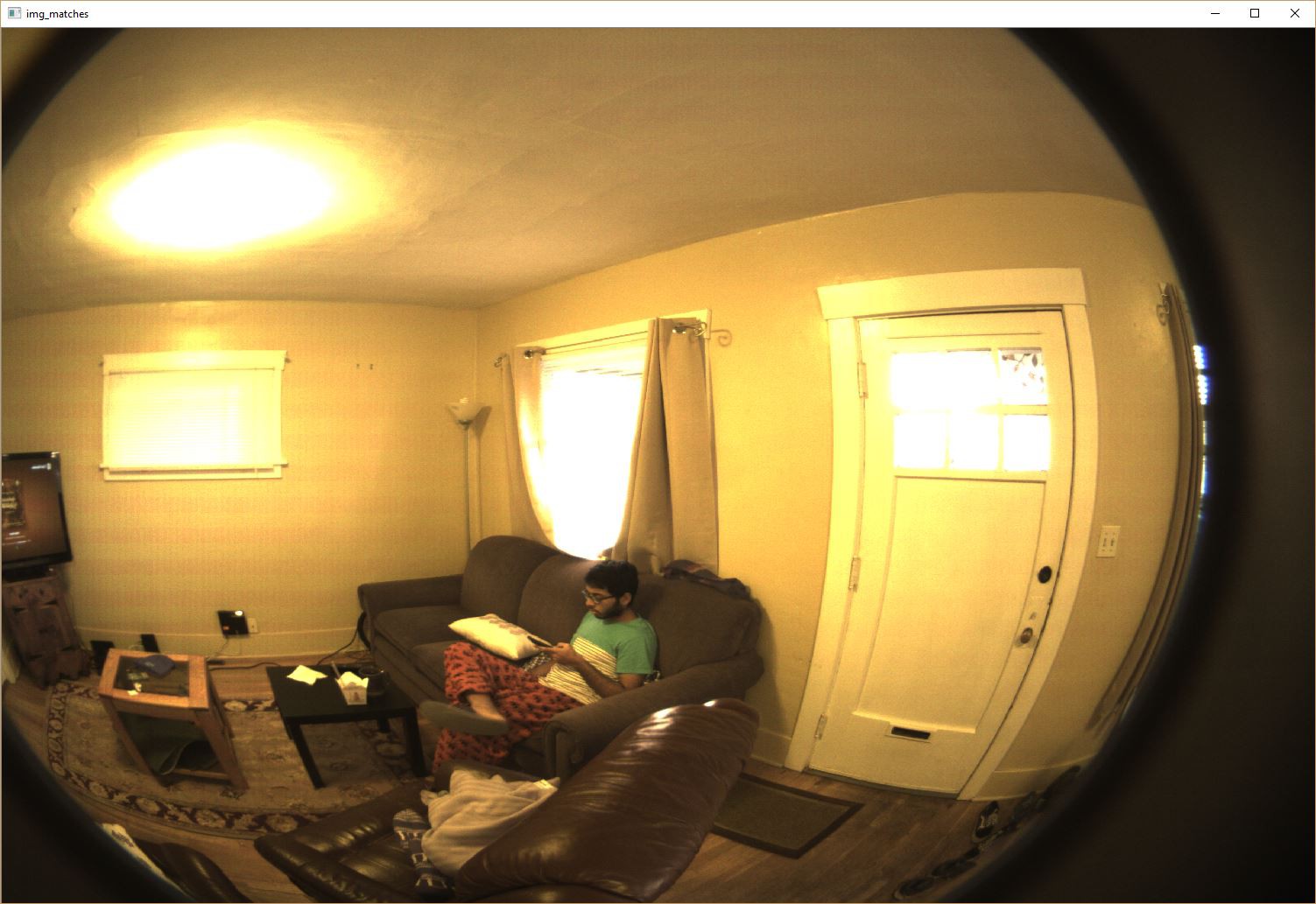
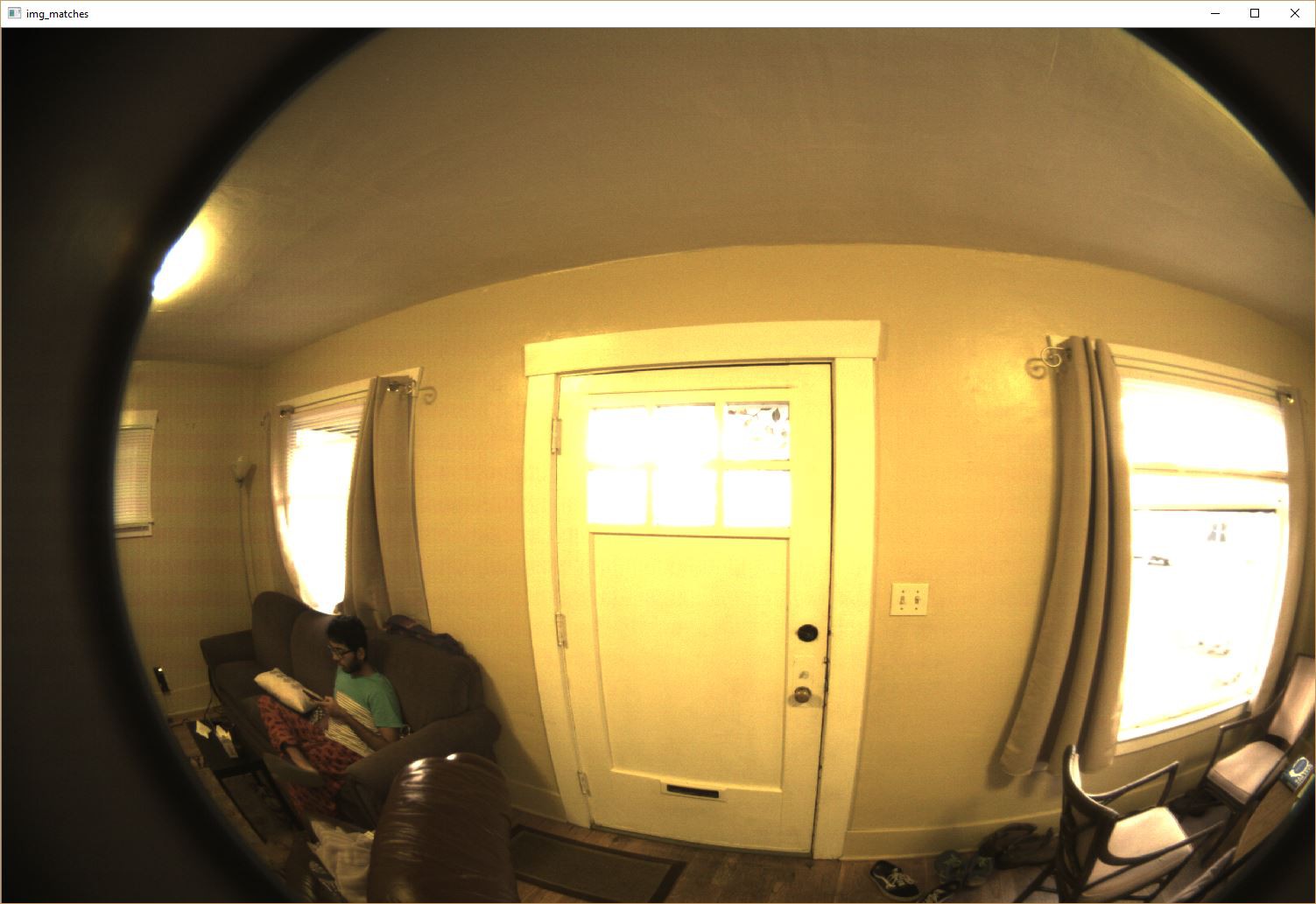
Here are three of the eight original images that we get from each camera:

The 8 images are then de-warped and converted to spherical projection. Here is the initial 360 photo produced from the guess parameters.
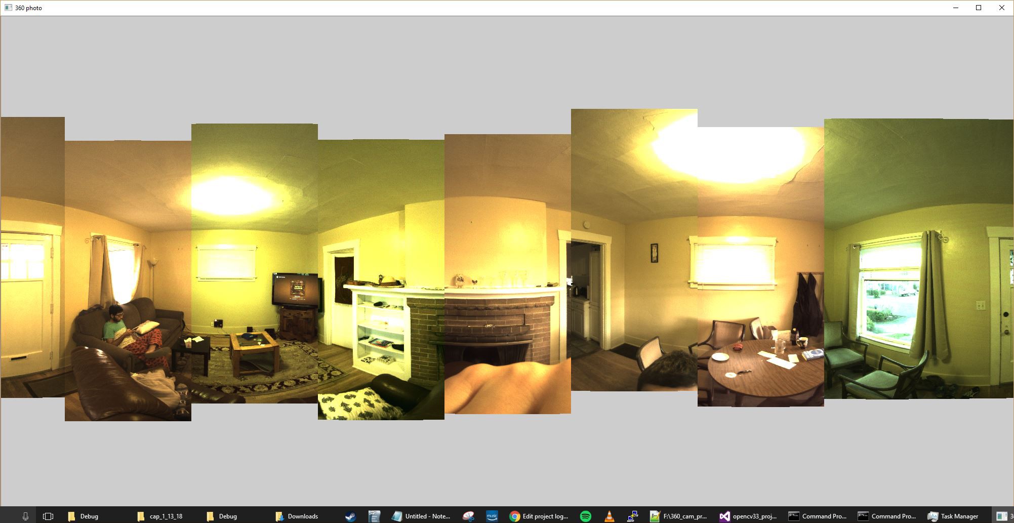
It looks pretty decent, but there are clear vertical misalignments between some of the images.
Using SURF, features are extracted from each image and matched to the features in the image from the next camera to the left, as shown below.
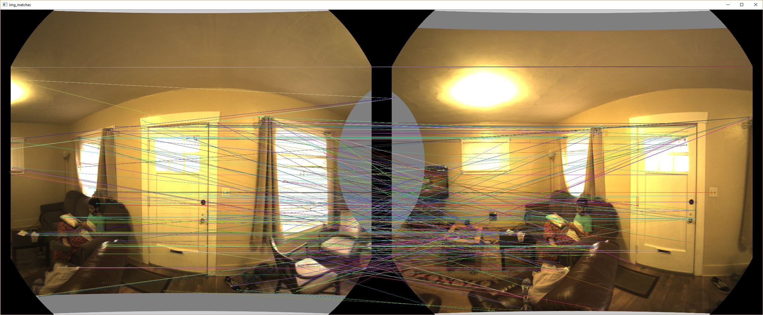
Features that are found in images from three adjacent cameras are kept and added to a list. An example of one of these features is shown below.

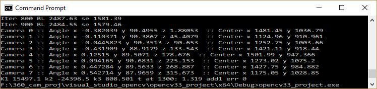
You can clearly see my roommate's shirt in each of the three original images. The coordinates of the shirt are reversed from the spherical projection to coordinates in the original projection, and used to guess a 3D vector from each camera. If the parameters for the cameras are perfect, these vectors should intersect in 3D space at the point where the shirt is, relative to the cameras. The iterative algorithm works to refine the 3D parameters for each camera to get the vectors for each of the features to align as closely as possible. Once the algorithm is done, the new parameters for each camera are displayed and saved to a file that can be read by the stitching software.
Here's the left-eye view of the final stitched 360 photo:
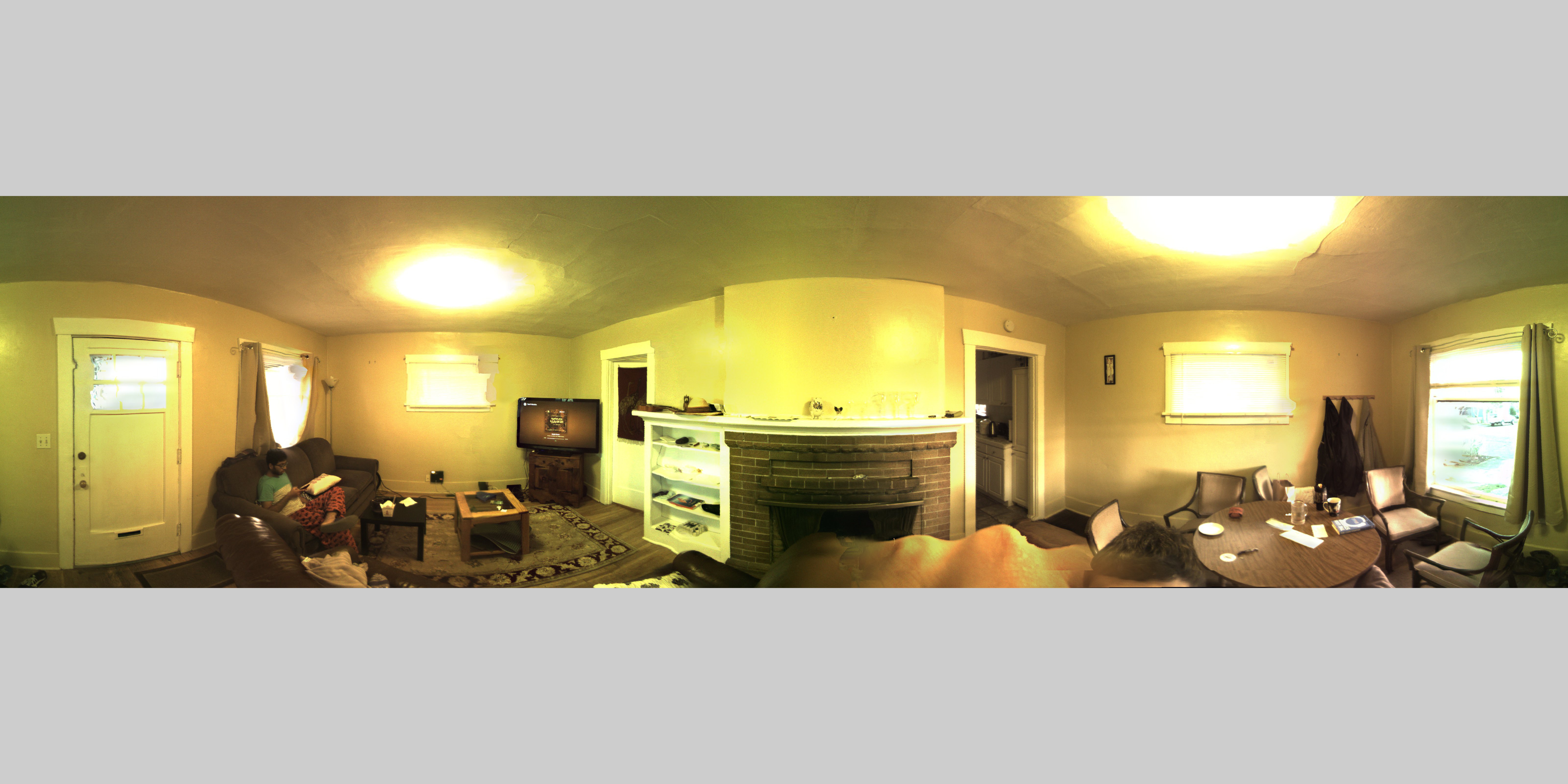
As you can see, there's still some distortion, but the vertical misalignment has been greatly reduced.
Discussions
Become a Hackaday.io Member
Create an account to leave a comment. Already have an account? Log In.