 Stephanie Stoll
In this part I will discuss the electronic design and sensor modalities of the hand prototype.
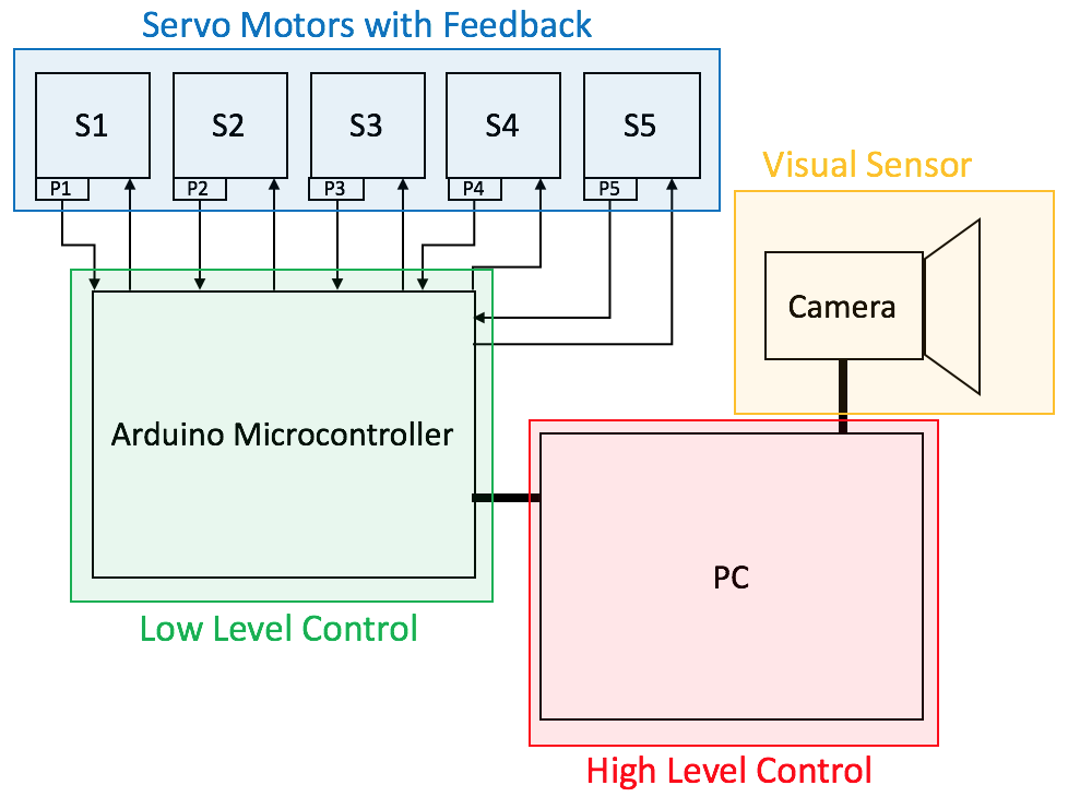
This is an overview of the electronics and sensors used:
Sensors and Servos
Like the design of the hand chassis the electronic design and sensor modalities evolved over time.
I originally intended to use force-sensitive resistors to measure whether a finger has made contact with an object. The resistors’ range and accuracy on breadboard was acceptable, however, when integrated into the hand I found that they were prone to breakage and often did not encounter enough pressure to change resistance when in contact with an object.
I found an alternative in using analogue feedback servos (I went with the Batan S1213), which allowed me to read their potentiometer wiper positions through an analogue input on the Arduino. This would allow me to estimate each servo’s actual position as opposed to just the position written to it. The actual position and the position command differ when a finger has encountered resistance in the form of an object, which allowed me to record each finger’s servo’s actual position when grasping an object.
For more on analogue feedback servos check out Adafruit's awesome toturial:
https://learn.adafruit.com/analog-feedback-servos/about-servos-and-feedback
heres a flow chart from the article that sums it up:
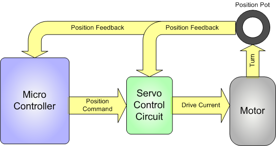 Analog feedback servo motor feeding the potentiometer information from the motor shaft to the microcontroller
The Microcontroller
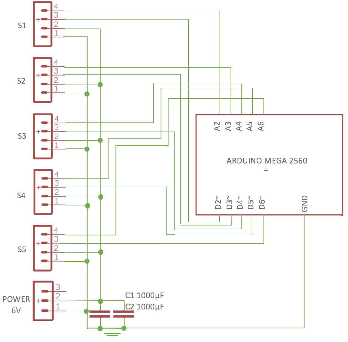
After starting off with an Arduino UnoI decided to use an Arduino Mega 2560 because it has loads of analog inputs should I want to add more sensors in the future.
The analogue feedback sensors are controlled by PWM pins D2-D6 on the Arduino Mega 2560, and the feedback values read by analogue inputs A2 – A6:
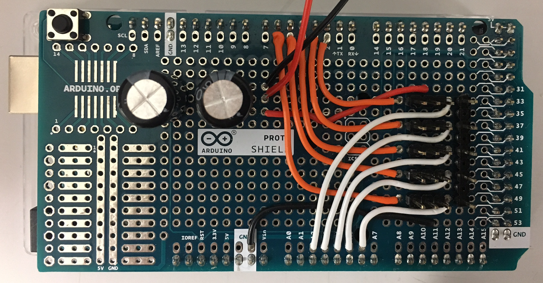
This design was transferred from breadboard onto an Arduino Mega shield:
The servos are powered by a 6 Volt power supply, whilst the Arduino is powered and connected to a computer via USB. The camera responsible for collecting visual data is directly connected to the computer via USB as well.
Discussions
Become a Hackaday.io Member
Create an account to leave a comment. Already have an account? Log In.