 Stephanie Stoll
In here I will talk about the low-level control API I wrote to run the hand and the API to collect training data to be used to train the CNNs at the heart of the high-level control.
The low-level API controlling the hand's servos is completely detached from the high-level control making the grasping choices, their only connection being a serial line. This means the hand prototype could be used for any kind of robotic grasping application and the high-level control could easily be modified to work with a different piece of hardware. I will discuss the high-level control at a later stage, so for now let's look at the low-level control.
Low-Level Control API
The low-level control API was written in Arduino C/C++ and is based around the Arduino Servo library. The API consists of two classes, Finger and Hand:
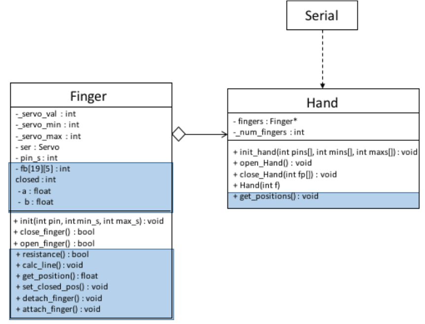 UML diagram of low-level API. Parts of the extended API used to collect training data are marked in blue.
A hand is created by giving the number of fingers (with a maximum of five). The constructor of Hand then creates the number of fingers specified and puts them into the fingers array. The Hand then requires the pin numbers each finger is connected to on the Arduino, as well as the minimum and maximum servo values for each. This is necessary to assure that no servo is overdriven, snapping a tendon. These values are passed on to the appropriate fingers. A finger is initialised by attaching and setting up an instance of Arduino Servo. The hand can then be opened and closed by calling open_Hand() and close_Hand(int fp[]), the latter requiring the array of activated and inactivated fingers from the high-level control. Open_Hand() and close_Hand() then call the open and close functions of each activated finger.
All communication between the high and low level control takes place via serial. The Arduino Mega 2560 has four hardware serial ports, of which one is connected to the USB device port via a USB-TTL Serial converter. This allows for communication between the Arduino IDE and the Arduino Mega 2560 via USB, for example when uploading sketches or using the IDE’s serial monitor. But the USB connection can also be used as a serial port between the Arduino and another application, in this case the python-based high-level control. On Linux and OSX the board is recognised as a virtual COM port automatically.
On the Arduino’s side, serial communication is handled by the Arduino Serial library, which has facilities for setting up, reading from and writing to the serial port. Python’s pySerial library is responsible for communicating from the high-level control to the Arduino. In order for the two sides to communicate, their serial baud rates need to be matched. The baud rate sets the speed with which data is sent via serial in bits-per-second. In our system, the baud rate is set to 115200 bps, as this is fast enough for the task at hand (pun intended) whilst keeping transmissions stable.
Extensions for Training Data Collection
To collect the feedback data I wrote an extended low-level API that records servo feedback during the closing process of the hand and compares it to expected values.
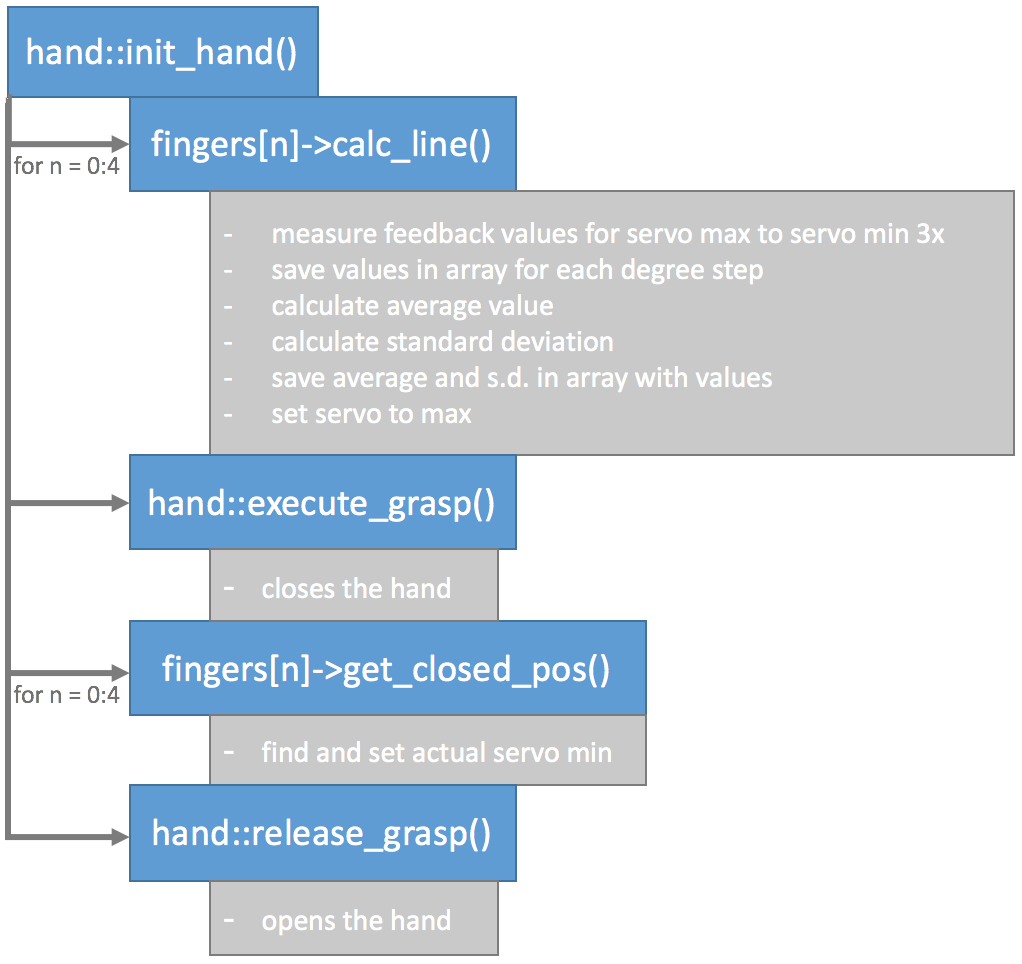
As the feedback sensors do not behave in an ideal way, a calibration routine is necessary to acquire meaningful readings. In theory, the feedback voltage measured at the potentiometer should be linear with respect to degrees of rotation of the servo motor shaft. This would allow to take a feedback measurement at the minimum and maximum positions of the servo and interpolate between them to find any other expected feedback values.
However, when measuring the actual feedback, I found that the response was nonlinear for the range between 180 and 140 degrees. When measuring values over multiple servo turns, I found that data was prone to varying, meaning that relying on only one maximum and one minimum measurement could lead to a line that would not fit the average response for the linear part of the feedback curve. The varying readings are likely down to tolerances in the sensors and fluctuations in the power supply.
The calibration routine developed accounts for both the nonlinear feedback response and variance in readings by taking readings over multiple turns between the maximum and minimum degree of each servo in intervals of ten degrees. For each degree, the average and standard deviation of all measurements is calculated and stored. The average is used as the expected feedback value for the servo at this degree, and the standard deviation used as a tolerance. After taking the measurements the hand is closed to measure each servo’s actual minimum degree value when applying the feedback measurement. The hand is then opened to finish the calibration routine. Here's a flowchart summarising all that:
After calibrating the hand the servo feedback readings can be used to stop a finger from closing further after encountering resistance from an object. Stopping the finger when the feedback exceeds the threshold calibrated, protects the servo motors, the object, as well as the hand itself from damage. It is also possible to tell at which angle a finger has made contact with an object, giving information about its position and dimensions.
I encountered difficulties when measuring feedback for each finger as soon as one finger encountered a resistance. This would cause the appropriate finger’s feedback to exceed the threshold, however, the feedback for all other fingers would also increase and exceed their thresholds, causing them to stop moving, without being impeded by an object. After ruling out any part of the code causing this issue, I found the problem in the hardware setup. As the feedback is directly fed to the Arduino from the servo motor’s shaft potentiometer, the feedback voltage measured as Vout is in reference to Vcc. As previously mentioned, fluctuations in Vcc would cause proportional variations in the feedback read from the servos. When a finger encounters a resistance, its servo motor will draw more current. This causes a drop in Vcc, which means Vout loses its reference, changing its value.
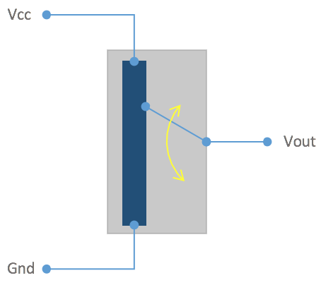 Reading feedback voltage from a potentiometer. The potentiomer's Vout is referenced between Vcc and ground. A change in Vcc hence changes Vout.
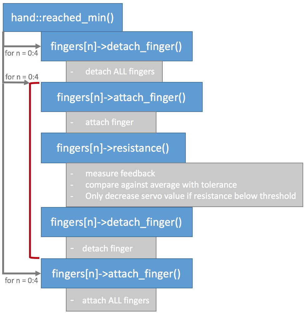
To circumvent this issue each servo needs to be measured in a separate circuit. This could be achieved by driving each servo motor with its own power supply. However, it is also possible to separate the servos by attaching and detaching them from the circuit in software. If a servo is detached it no longer receives or tries to act on positional commands from the Arduino and therefore draws no current. Detaching all servos and then only attaching one servo at a time to take a feedback reading results in correct values:
That's it on the low-level control, I uploaded the code on here for you. It is far from brilliant code so feel free to let me know how to improve.
Discussions
Become a Hackaday.io Member
Create an account to leave a comment. Already have an account? Log In.