My robot design uses a camera with a very very wide-angle lens. I bought a Pi camera module with a 175 degree wide angle lens which fits the bill (https://www.ebay.co.uk/sch/i.html?_from=R40&_trksid=p2054502.m570.l1313.TR0.TRC0.H0.X++Camera+Module+Board+1080P+5MP+175%C2%B0+Wide+Angle.TRS0&_nkw=++Camera+Module+Board+1080P+5MP+175%C2%B0+Wide+Angle&_sacat=0). It's not a Pi-foundation official one (which it seems the Pi foundation abhors so much that they put a cryto chip on the v2 module to stop people making knock offs https://www.raspberrypi.org/forums/viewtopic.php?f=43&t=149426#p982590. If there was an official 175 degree module, I'd have bought one).
175 degrees means that there's a decent amount of distortion in the image (fish eye style), which I want to get rid of so I can use the images for something useful. So, I need to undistort them.
OpenCV will end up in my image pipeline at some point, and it is able to correct lens distortion itself - but CPU power is really precious on the Pi (even the Pi3 - Cortex-A53 is a deliberately weak CPU as far as ARMv8 goes - it's designed for high efficiency, not performance). So, correction on the CPU doesn't look appealing - but we have got a nice OpenGL ES 2.0 GPU sat in the Pi which will be otherwise un-utilised in my robot - so let's kick that in for the lens correcion!
Step 1. Hello Triangle
I don't know OpenGL ES. I'd never done any GPU programming in my life. So step 1 was to find the most basic Open GL ES example I could.
Thankfully, my friend Ciro Santilli had just what I needed - a tiny, self-contained "Hello Triangle" example in C: https://github.com/cirosantilli/cpp-cheat/blob/master/opengl/gles/triangle.c
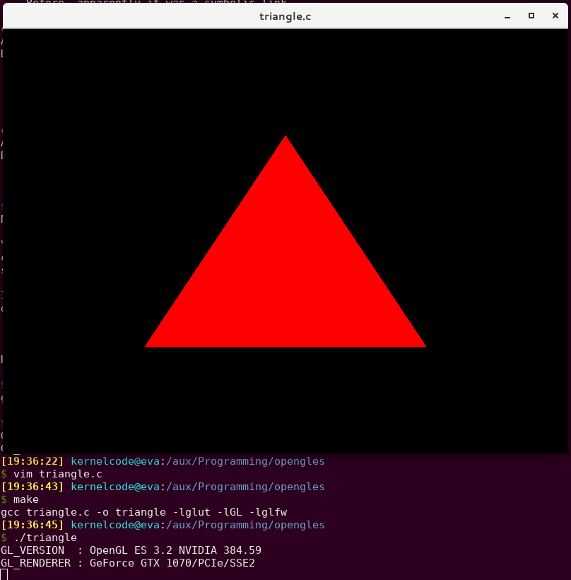
Fabulous! We can draw a triangle and we didn't even need to write any code yet!
Step 2. Textured Triangle
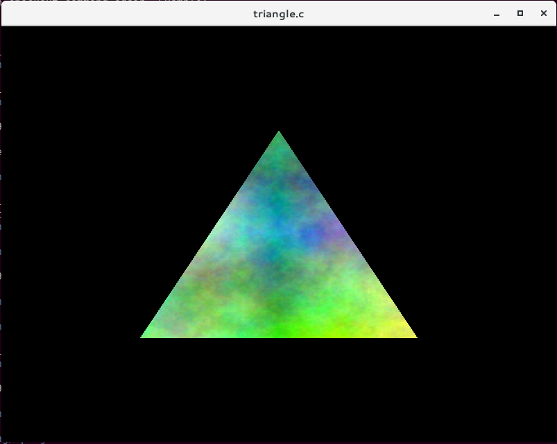
OK, so we can draw a triangle and fill it with a single colour. That's not much use in the real world - what we actually want to do is draw something onto the triangle. That's called texturing.
So my next step was to add some code to import images (using libnetpbm because it's literally as simple as you can get). Once you've loaded the image data into memory somewhere, you create an OpenGL ES texture with it, hook that up to the fragment shader - and voila:
Creating the texture:
glGenTextures(1, &tex);
glActiveTexture(GL_TEXTURE0);
glBindTexture(GL_TEXTURE_2D, tex);
glTexParameteri(GL_TEXTURE_2D, GL_TEXTURE_WRAP_S, GL_CLAMP_TO_EDGE);
glTexParameteri(GL_TEXTURE_2D, GL_TEXTURE_WRAP_T, GL_CLAMP_TO_EDGE);
glTexParameteri(GL_TEXTURE_2D, GL_TEXTURE_MIN_FILTER, GL_LINEAR);
glTexParameteri(GL_TEXTURE_2D, GL_TEXTURE_MAG_FILTER, GL_LINEAR);
glTexImage2D(GL_TEXTURE_2D, 0, GL_RGB, texture->width, texture->height, 0, GL_RGB, GL_UNSIGNED_BYTE, texture->pixels);
glBindTexture(GL_TEXTURE_2D, 0);
For the vertex shader, we add some extra code to emit a texture coordinate as well as a vertex coordinate:
#version 100
attribute vec3 position;
varying highp vec2 v_TexCoord;
void main() {
   gl_Position = vec4(position, 1);
   v_TexCoord = vec2(position.x + 0.5, -position.y + 0.5);
}
And in the fragment shader, we use "texture2D" to read from the texture:
#version 100
varying highp vec2 v_TexCoord;
uniform sampler2D tex;
void main()
{
    gl_FragColor = texture2D(tex, v_TexCoord);
}
Now we're well on the way - we now know pretty much everything we need to know in order to do our lens correction.
Next little stepping-stone is to add in some co-ordinate transformation so that it's a little easier to think about coordinates in our "scene". I added a projection matrix which changes the GL "normalised device coordinates" (which are -1 to 1) to plain normalised coordinates (0 to 1) and to flip the Y axis so that 0,0 is in the top-left (the same as literally everything else in the world except for OpenGL).
Step 3. Drawing and mapping to a mesh
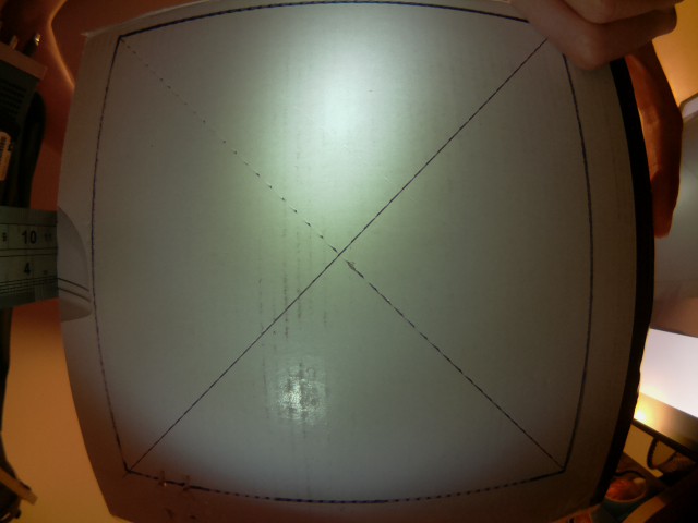
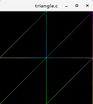
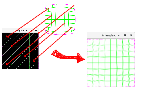
So, a single triangle is great - but we can't use just one triangle to do lens correction - we need a bunch of triangles which we'll then map on to the texture in such a way that it undoes the distortion added by the lens. The mesh will be created as a grid of pairs of triangles, which is pretty easy to do programmatically. Here's what a 2x2 mesh looks like (8 triangles):
I used GIMP to draw a test grid pattern, and then used the "Lens Distort" filter to distort it somewhat - then (mostly) by hand I wrote down the pixel coordinates of each line intersection and put that look-up table into the code, I created a 9x9 mesh with my new mesh generation code, and mapped each of the line intersection coordinates from the distorted image onto each vertex in the mesh. The end result is a nicely undistorted image: Success!
Step 4. Lens Models
I spent a while after this researching programmatic ways for describing the lens distortion - hand-transcribing coordinates wasn't something I was planning to do again.
There's a few different algorithms and methods (Brown's Model is a popular one for describing lens distortion). There's also software tools already which do the correction for you - Hugin is one of them, and it's mean to be able to figure out the "distortion parameters" of your lens - but I couldn't get it to give me any meaningful numbers.
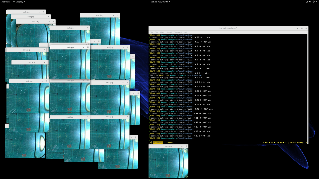
I spent a long long time running ImageMagick on a photo from my camera and just fiddling with the parameters until it looked "OK":
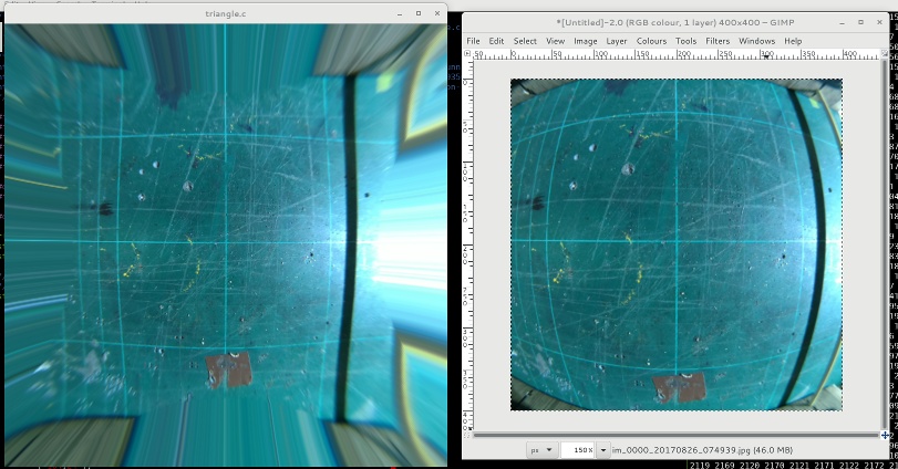
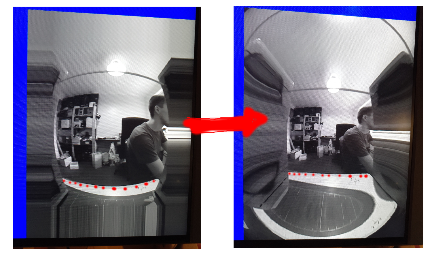
Some more code later and I was able to correct one of my camera stills pretty satisfactorily (bendy lines on the right - straighter lines on the left):
It's perhaps worth clarifying at this point, that I'm not calculating the distortion itself on the GPU. At application start up, I calculate a mesh, and a texture co-ordinate for each vertex in the mesh - the GPU then just does a simple sampling using these coordinates. This is more efficient - pre calculating the mesh only needs to be done one, and the GPU does basically no calculation in the shaders.
Step 5. Porting to the Pi
The more eagle-eyed readers might have spotted already that so far I've been running everything on my NVidia desktop card. Now I had something worthwhile I set to porting it to the Pi.
Ciro's original code was using GLFW to interface with the operating system - this gives us a window to draw in. On the Pi, we're instead going to use the Pi's EGL implementation to talk to the display hardware more-or-less directly. The Pi ships with some simple examples in /opt/vc/src/hello_pi, so I just nicked all of the setup code from one of them, and wrapped that up in a tiny little abstraction that lets me run on both the Pi and my desktop. The abstraction has only three (four) functions:
struct pint {
    void (*swap_buffers)(struct pint *);
    bool (*should_end)(struct pint *);
    void (*terminate)(struct pint *);
};
extern struct pint *pint_initialise(uint32_t width, uint32_t height);
I split out the GLFW code from my existing source, and implemented the new abstraction in both GLFW and the Pi EGL interface.
After a little compiler back-and-forth I had the same code running on the Pi - and was relieved to see that it was running just fine at 60 FPS! (Not too surprising given that the GPU is doing naff all).
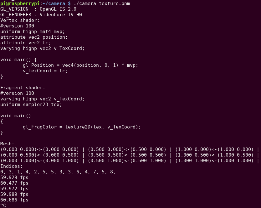
Step 6. Texture fast-path
OK, so now the last piece of the puzzle is to actually get data from the camera instead of my wimpy libnetpbm imports.
One way to do this is to capture from the camera to a memory buffer (like raspistill does), and then upload that to a texture, and then use that in the GL shaders, just like with the PNM images. The problem is, this is slow. You have to copy all the data from the camera into a buffer somewhere, then you have to upload that to the GPU (which probably involves a format conversion into some internal format for the GPU), and you have to do this every frame. Remember the whole point of this exercise is to leave the CPU as idle as possible to be used for other robot business.
Luckily, the Pi multimedia stack has a direct-to-texture path from the Camera to the GPU. This is implemented via EGLImage and the OES_EGL_image_external extension.
Raspistill has some example for how to make this work, and I found SanderVocke's minimal example, which basically takes the Raspistill code and distils it down to the bare minimum. I used SanderVocke's code as my starting point.
It boils down to a fairly small number of changes from what we had before. Firstly, instead of creating the texture from data in memory, you use a special texture type, and some EGL magic:
glBindTexture(GL_TEXTURE_EXTERNAL_OES, tex);
img = eglCreateImageKHR(GDisplay, EGL_NO_CONTEXT, EGL_IMAGE_BRCM_MULTIMEDIA_Y, (EGLClientBuffer) buf->data, NULL);
glEGLImageTargetTexture2DOES(GL_TEXTURE_EXTERNAL_OES, img);
Instead of binding GL_TEXTURE_2D, we bind GL_TEXTURE_OES, then we create an EGLImage with the Pi-special target "EGL_IMAGE_BRCOM_MULTIMEDIA_Y" - this tells EGL that we want to get the "Y" (luminance) plane from the buffer, and create an EGLImage from it. Lastly, we tell EGL to target that image at the texture.
Secondly, in the fragment shader, instead of using a normal "uniform" for the texture, we have to use a special type to use the external image as a texture:
#version 100
#extension GL_OES_EGL_image_external : require
uniform samplerExternalOES tex;
varying highp vec2 v_TexCoord;
void main()
{
    gl_FragColor = texture2D(tex, v_TexCoord);
}
and lastly, in between each frame of rendering, we have to dequeue a new buffer from the camera:
glUseProgram(shader_program);
glUniform1i(texLoc, 0);
glUniformMatrix4fv(mvpLoc, 1, GL_FALSE, mat);
glActiveTexture(GL_TEXTURE0);
/* Wait for a new frame from the camera */
while (!camera_read_frame());
glBindBuffer(GL_ARRAY_BUFFER, mesh->mhandle);
glBindBuffer(GL_ELEMENT_ARRAY_BUFFER, mesh->ihandle);
glDrawElements(GL_TRIANGLE_STRIP, mesh->nindices, GL_UNSIGNED_SHORT, 0);
pint->swap_buffers(pint);
An hour or two of fiddling later, and I finally had a live video feed on my Pi's monitor. Some things to note are:
- You must wait until you have a frame from the camera before you call eglSwapBuffers()
- That's what the while() loop is for on camera_read_frame(). Without this, it crashes within a couple of loops
- You must shut-down the camera correctly - otherwise it locks up and you can't use it again until you reboot
- I must say that's some pretty shoddy design/implementation on the Foundation and/or Broadcom. If the process dies, they should clean everything up appropriately, in my opinion.
One Weekend Later
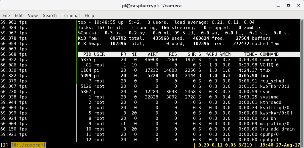
All right! So, after all is said and done, I now have the camera hooked up to some GL code, I can (mostly) undistort my images at 60 FPS, and the Pi CPU consumption is less than 5%. I'd say that's a win for a weekend's work!
Drawing top in tmux over SSH is almost consuming as much CPU as my camera application at 60 FPS!!
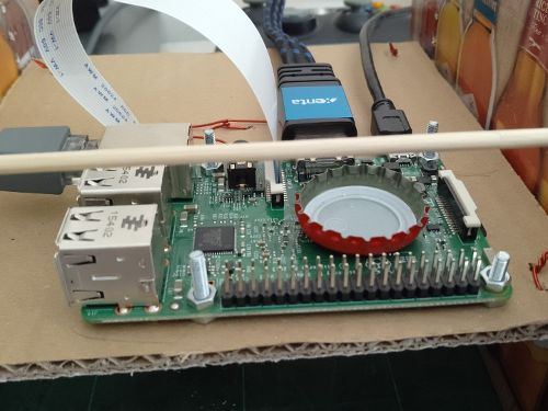
It might not be a significant CPU load, but I did notice the Pi was getting pretty warm (it's quite a warm day) so I had to lay a bottle cap on the CPU to help cool it down
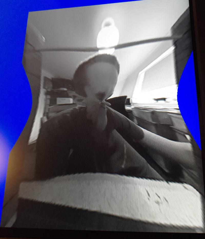
Also what good is writing a camera shader application without a few silly alien pictures?
Next Steps
So, I've got most of the building blocks I need - what's next for the camera subsystem?
- I will probably switch back to some form of hand-generated mesh for the distortion parameters, I think I can get a better result this way - and given I only have one camera in one position to deal with, it's not a huge overhead to do it once.
- Get the output from the camera shader into the program!
- So far all I've done is display the image. That's not much use for actually using the camera for something. So I need code to export the image. This is going to be a significant CPU hog - so I need to reduce the image size(s) as far as I possibly can before I read it off the GPU
- Moar processing!
- I probably want to do a bit more processing of the image in OpenGL before I get it out. I expect I'll do some kind of thresholding and perhaps a blur to give me some nicer input to OpenCV - as with the distortion, OpenCV can do it itself - but it should be a lot cheaper in terms of CPU time to do it on the GPU
- RGB output
- In my system, I need two outputs from the camera: One for OpenCV (luminance will do fine for that), and one that RGB for looking at. So I need to write another shader to convert YUV to RGB.
Discussions
Become a Hackaday.io Member
Create an account to leave a comment. Already have an account? Log In.
Hi ! While it's now 2019, I'd still be very interested in your solution! For doing efficient fisheye correction on the Pi there still don't seem to be an huge amount of examples out there. Would you mind sharing your code with me or is there anything on github from you? Many thanks! M
Are you sure? yes | no